Page 4527 of 5598

SE-68
< DTC/CIRCUIT DIAGNOSIS >
POWER SUPPLY AND GROUND CIRCUIT
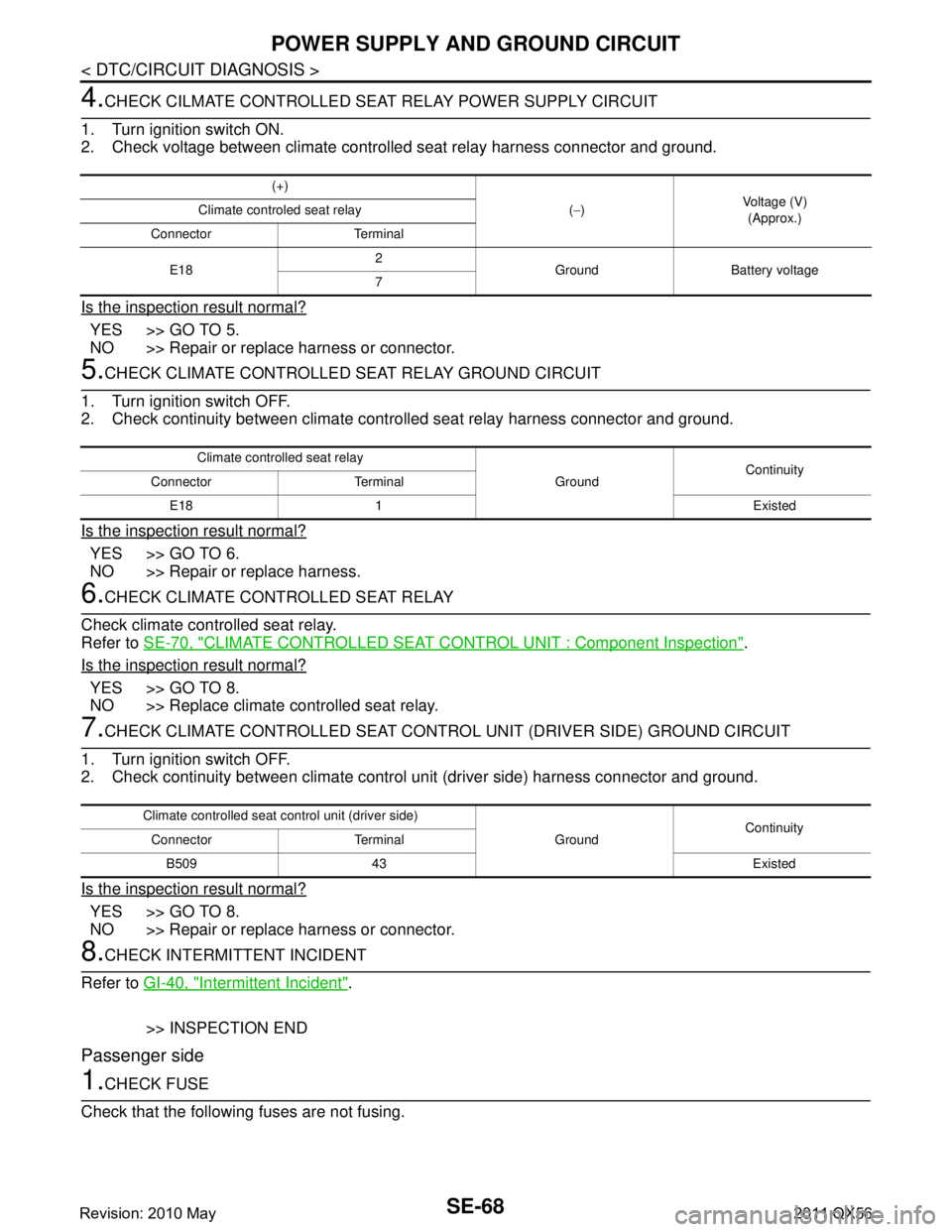
4.CHECK CILMATE CONTROLLED SEAT RELAY POWER SUPPLY CIRCUIT
1. Turn ignition switch ON.
2. Check voltage between climate controlled seat relay harness connector and ground.
Is the inspection result normal?
YES >> GO TO 5.
NO >> Repair or replace harness or connector.
5.CHECK CLIMATE CONTROLLED SEAT RELAY GROUND CIRCUIT
1. Turn ignition switch OFF.
2. Check continuity between climate cont rolled seat relay harness connector and ground.
Is the inspection result normal?
YES >> GO TO 6.
NO >> Repair or replace harness.
6.CHECK CLIMATE CONTROLLED SEAT RELAY
Check climate controlled seat relay.
Refer to SE-70, "
CLIMATE CONTROLLED SEAT CONTROL UNIT : Component Inspection".
Is the inspection result normal?
YES >> GO TO 8.
NO >> Replace climate controlled seat relay.
7.CHECK CLIMATE CONTROLLED SEAT CONTRO L UNIT (DRIVER SIDE) GROUND CIRCUIT
1. Turn ignition switch OFF.
2. Check continuity between climate contro l unit (driver side) harness connector and ground.
Is the inspection result normal?
YES >> GO TO 8.
NO >> Repair or replace harness or connector.
8.CHECK INTERMITTENT INCIDENT
Refer to GI-40, "
Intermittent Incident".
>> INSPECTION END
Passenger side
1.CHECK FUSE
Check that the following fuses are not fusing.
(+)
(− ) Voltage (V)
(Approx.)
Climate controled seat relay
Connector Terminal
E18 2
Ground Battery voltage
7
Climate controlled seat relay
GroundContinuity
Connector Terminal
E18 1 Existed
Climate controlled seat co ntrol unit (driver side)
GroundContinuity
Connector Terminal
B509 43 Existed
Revision: 2010 May2011 QX56
Page 5144 of 5598
![INFINITI QX56 2011 Factory Service Manual
TM-56
< SYSTEM DESCRIPTION >[7AT: RE7R01B]
SYSTEM
Input/Output Signal Chart
*: This signal is transmitted via CAN communication line.
The TCM receives the manual mode signal, non-manual mode signal INFINITI QX56 2011 Factory Service Manual
TM-56
< SYSTEM DESCRIPTION >[7AT: RE7R01B]
SYSTEM
Input/Output Signal Chart
*: This signal is transmitted via CAN communication line.
The TCM receives the manual mode signal, non-manual mode signal](/manual-img/42/57033/w960_57033-5143.png)
TM-56
< SYSTEM DESCRIPTION >[7AT: RE7R01B]
SYSTEM
Input/Output Signal Chart
*: This signal is transmitted via CAN communication line.
The TCM receives the manual mode signal, non-manual mode signal, manual mode shift up signal and
manual mode shift down signal from combination meter via CAN communication line. The TCM shifts shift
pattern control to the manual mode based on these signal s, and then shifts the A/T by operating each sole-
noid valve according to the shift operation of the driver.
The TCM prohibits the manual mode while being in fail-safe mode due to an A/T malfunction, etc. Refer to TM-74, "
Fail-Safe".
Manual Mode Information
The TCM transmits the manual mode shift refusal signal to the combination meter if the TCM refuses the
transmission from the driving status of vehicle when the selector lever shifts to “UP (+ side)” or “DOWN (−
side)” side. The combination meter blinks shift indicator on the combination meter and sounds the buzzer to
indicate the driver that the shifting is not performed when receiving this signal. However, the TCM does not
transmit the manual mode shift refusal signal in the conditions as per the following.
- When the selector lever shifts to “DOWN ( − side)” side in 1GR.
- When the selector lever shifts to “UP (+ side)” side in 7GR.
LOCK-UP CONTROL
LOCK-UP CONTROL : System DiagramINFOID:0000000006226777
LOCK-UP CONTROL : System DescriptionINFOID:0000000006226778
The torque converter clutch piston in the torque conv erter is engaged to eliminate torque converter slip to
increase power transmission efficiency.
Lock-up operation, however, is prohibited when A/T fluid temperature is too low.
The torque converter clutch control valve operation is controlled by the torque converter clutch solenoid
valve, which is controlled by a signal from TCM, and the torque converter clutch control valve engages or
releases the torque converter clutch piston.
Item Signal TCM function Actuator
Output speed sensor Vehicle speed
Manual mode High and low reverse clutch
solenoid valve
Direct clutch solenoid valve
Input clutch solenoid valve
Low brake solenoid valve
2346 brake solenoid valve
Front brake solenoid valve
Torque converter clutch sole- noid valve
Line pressure solenoid valve
Anti-interlock solenoid valve
A/T fluid temperature sensor ATF temperature
ECM
Engine speed signal*
Accelerator pedal position sig-
nal*
Combination meter Manual mode signal*
Non-manual mode signal*
Manual mode shift up signal*
Manual mode shift down signal*
JSDIA1350GB
Revision: 2010 May2011 QX56
Page 5443 of 5598

WCS
POWER SUPPLY AND GROUND CIRCUITWCS-39
< DTC/CIRCUIT DIAGNOSIS >
C
DE
F
G H
I
J
K L
M B A
O P
DTC/CIRCUIT DIAGNOSIS
POWER SUPPLY AND GROUND CIRCUIT
COMBINATION METER
COMBINATION METER : Diagnosis ProcedureINFOID:0000000006222743
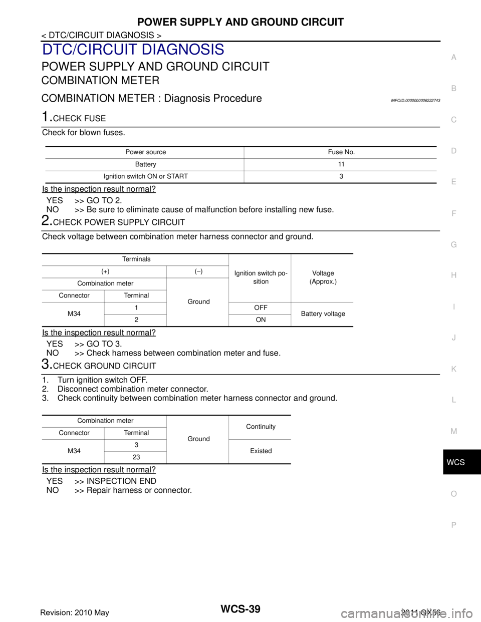
1.CHECK FUSE
Check for blown fuses.
Is the inspection result normal?
YES >> GO TO 2.
NO >> Be sure to eliminate cause of malfunction before installing new fuse.
2.CHECK POWER SUPPLY CIRCUIT
Check voltage between combination meter harness connector and ground.
Is the inspection result normal?
YES >> GO TO 3.
NO >> Check harness between combination meter and fuse.
3.CHECK GROUND CIRCUIT
1. Turn ignition switch OFF.
2. Disconnect combination meter connector.
3. Check continuity between combination meter harness connector and ground.
Is the inspection result normal?
YES >> INSPECTION END
NO >> Repair harness or connector.
Power source Fuse No.
Battery 11
Ignition switch ON or START 3
Te r m i n a l s
Ignition switch po-sition Vo l ta g e
(Approx.)
(+) (
−)
Combination meter
Ground
Connector Terminal
M34 1OFF
Battery voltage
2ON
Combination meter
GroundContinuity
Connector Terminal
M34 3
Existed
23
Revision: 2010 May2011 QX56
Page 5554 of 5598
WIPER AND WASHER FUSEWW-35
< DTC/CIRCUIT DIAGNOSIS >
C
DE
F
G H
I
J
K
M A
B
WW
N
O P
DTC/CIRCUIT DIAGNOSIS
WIPER AND WASHER FUSE
Diagnosis ProcedureINFOID:0000000006300467
1.CHECK FUSES
Check that the following fuses is not fusing.
Is the inspection result normal?
YES >> INSPECTION END
NO >> Replace the fuse with a new one after repairing the applicable circuit.
Unit Location No. Capacity
Front wiper motor IPDM E/R 45 30 A
Headlamp washer relay - U 30 A
Washer pump Fuse block (J/B) 1 10 A
Revision: 2010 May2011 QX56
Page:
< prev 1-8 9-16 17-24