2011 INFINITI QX56 BATTERY
[x] Cancel search: BATTERYPage 1699 of 5598
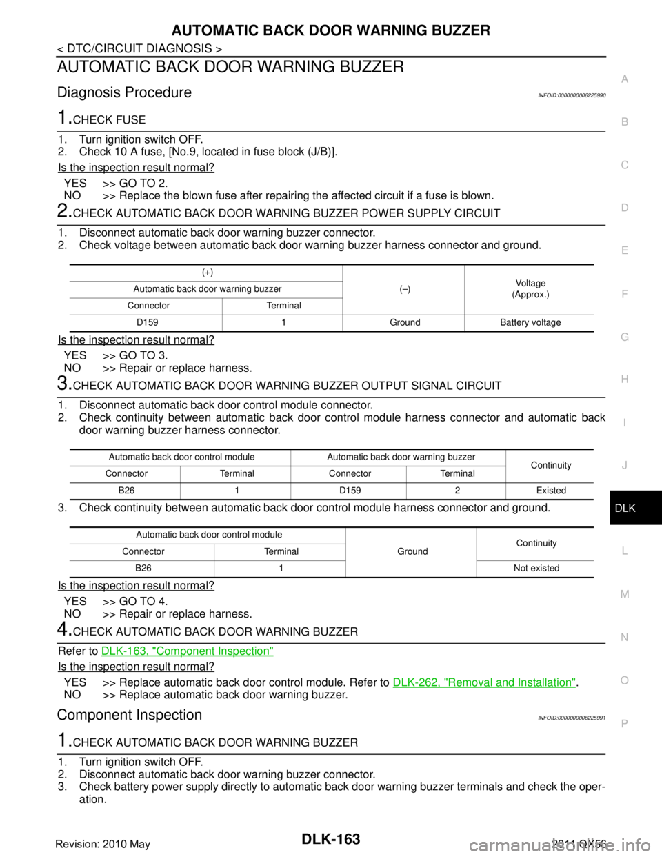
AUTOMATIC BACK DOOR WARNING BUZZERDLK-163
< DTC/CIRCUIT DIAGNOSIS >
C
DE
F
G H
I
J
L
M A
B
DLK
N
O P
AUTOMATIC BACK DOOR WARNING BUZZER
Diagnosis ProcedureINFOID:0000000006225990
1.CHECK FUSE
1. Turn ignition switch OFF.
2. Check 10 A fuse, [No.9, located in fuse block (J/B)].
Is the inspection result normal?
YES >> GO TO 2.
NO >> Replace the blown fuse after repairing the affected circuit if a fuse is blown.
2.CHECK AUTOMATIC BACK DOOR WARNI NG BUZZER POWER SUPPLY CIRCUIT
1. Disconnect automatic back door warning buzzer connector.
2. Check voltage between automatic back door warning buzzer harness connector and ground.
Is the inspection result normal?
YES >> GO TO 3.
NO >> Repair or replace harness.
3.CHECK AUTOMATIC BACK DOOR WARNING BUZZER OUTPUT SIGNAL CIRCUIT
1. Disconnect automatic back door control module connector.
2. Check continuity between automatic back door control module harness connector and automatic back
door warning buzzer harness connector.
3. Check continuity between automatic back door control module harness connector and ground.
Is the inspection result normal?
YES >> GO TO 4.
NO >> Repair or replace harness.
4.CHECK AUTOMATIC BACK DOOR WARNING BUZZER
Refer to DLK-163, "
Component Inspection"
Is the inspection result normal?
YES >> Replace automatic back door control module. Refer to DLK-262, "Removal and Installation".
NO >> Replace automatic back door warning buzzer.
Component InspectionINFOID:0000000006225991
1.CHECK AUTOMATIC BACK DOOR WARNING BUZZER
1. Turn ignition switch OFF.
2. Disconnect automatic back door warning buzzer connector.
3. Check battery power supply directly to automatic back door warning buzzer terminals and check the oper-
ation.
(+)
(–)Voltag e
(Approx.)
Automatic back door warning buzzer
Connector Terminal D159 1 Ground Battery voltage
Automatic back door control module Automatic back door warning buzzer Continuity
Connector Terminal Connector Terminal
B26 1 D159 2 Existed
Automatic back door control module GroundContinuity
Connector Terminal
B26 1 Not existed
Revision: 2010 May2011 QX56
Page 1702 of 5598
DLK-166
< DTC/CIRCUIT DIAGNOSIS >
INTEGRATED HOMELINK TRANSMITTER
INTEGRATED HOMELINK TRANSMITTER
Component Function CheckINFOID:0000000006256149
1.CHECK FUNCTION
Check that system receiver (garage door opener, et c.) operates with original hand-held transmitter.
Is the inspection result normal?
YES >> GO TO 2.
NO >> Receiver or hand-held transmitter is malfunctioning.
2.CHECK ILLUMINATE
1. Turn ignition switch OFF.
2. Does red light of transmitter illuminat e when any transmitter button is pressed?
Is the inspection result normal?
YES >> GO TO 3.
NO >> Refer to DLK-166, "
Diagnosis Procedure".
3.CHECK TRANSMITTER
Check transmitter with Tool*.
*:For details, refer to Technical Service Bulletin.
Is the inspection result normal?
YES >> Receiver or hand-held transmitter malfunction, not vehicle related.
NO >> Replace auto anti-dazzling inside mirror (integrated homelink transmitter).
Diagnosis ProcedureINFOID:0000000006256150
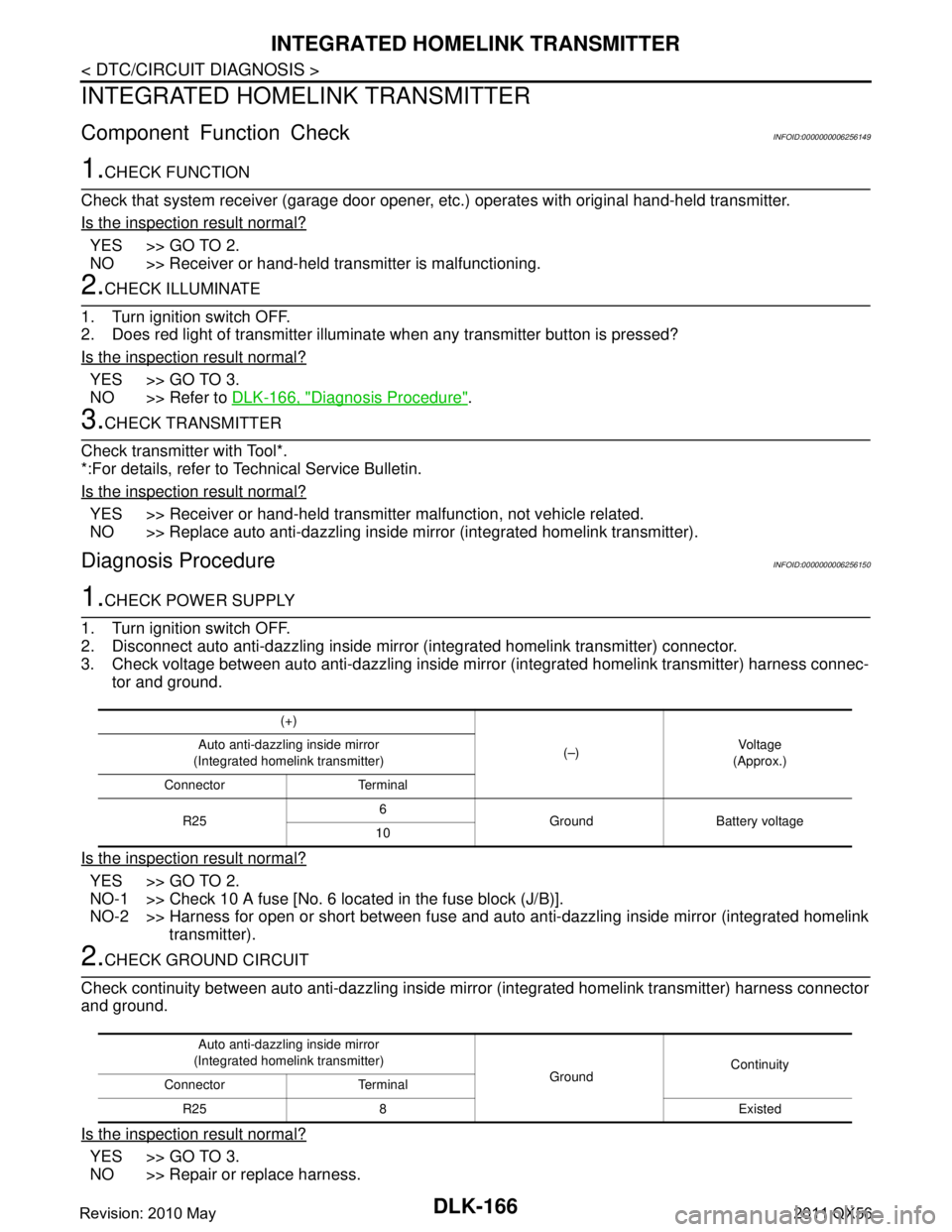
1.CHECK POWER SUPPLY
1. Turn ignition switch OFF.
2. Disconnect auto anti-dazzling inside mirror (integrated homelink transmitter) connector.
3. Check voltage between auto anti-dazzling inside mirro r (integrated homelink transmitter) harness connec-
tor and ground.
Is the inspection result normal?
YES >> GO TO 2.
NO-1 >> Check 10 A fuse [No. 6 located in the fuse block (J/B)].
NO-2 >> Harness for open or short between fuse and aut o anti-dazzling inside mirror (integrated homelink
transmitter).
2.CHECK GROUND CIRCUIT
Check continuity between auto anti-dazzling inside mi rror (integrated homelink transmitter) harness connector
and ground.
Is the inspection result normal?
YES >> GO TO 3.
NO >> Repair or replace harness.
(+)
(–)Vo l ta g e
(Approx.)
Auto anti-dazzling inside mirror
(Integrated homelink transmitter)
Connector Terminal
R25 6
Ground Battery voltage
10
Auto anti-dazzling inside mirror
(Integrated homelink transmitter) GroundContinuity
Connector Terminal
R25 8 Existed
Revision: 2010 May2011 QX56
Page 1731 of 5598
INTELLIGENT KEY LOW BATTERY WARNING DOES NOT OPERATE
DLK-195
< SYMPTOM DIAGNOSIS >
C
D E
F
G H
I
J
L
M A
B
DLK
N
O P
INTELLIGENT KEY LOW BATTERY WARNING DOES NOT OPERATE
DescriptionINFOID:0000000006226034
Intelligent Key low battery warning does not operat e for vehicle with information display models.
NOTE:
Warning functions operating condition is extremely comp licated, during operating confirmations, reconfirm the
list above twice in order to ensure proper operation. Refer to DLK-27, "
WARNING FUNCTION : System
Description".
Diagnosis ProcedureINFOID:0000000006226035
1.CHECK DTC WITH BCM
Check that DTC is not detected with BCM
Is the inspection result normal?
YES >> GO TO 2.
NO >> Perform trouble diagnosis relevant to DTC indicated.
2.CHECK DTC WITH COMBINATION METER
Check that DTC is not detected with combination meter
Is the inspection result normal?
YES >> GO TO 3.
NO >> Perform trouble diagnosis relevant to DTC indicated.
3.CHECK “LO- BATT OF KEY FOB WARN” SETTING IN “WORK SUPPORT”
1. Select “INTELLIGENT KEY” of “BCM”.
2. Select “LO- BATT OF KEY FOB WARN” in “WORK SUPPORT” mode.
3. Check “LO- BATT OF KEY FOB WARN” setting in “WORK SUPPORT”. Refer to DLK-41, "
INTELLIGENT KEY : CONSULT-III Function (BCM - INTELLIGENT KEY)".
Is the inspection result normal?
YES >> GO TO 4.
NO >> Set “ON” in “LO- BATT OF KEY FOB WARN”.
4.CHECK INTELLIGENT KEY
Check Intelligent Key.
Refer to DLK-145, "
ComponentFunctionCheck".
Is the inspection result normal?
YES >> GO TO 5.
NO >> Repair or replace the malfunctioning parts.
5.CHECK INSIDE KEY ANTENNA
Check inside key antenna.
Instrument center: Refer to DLK-104, "
DTC Logic".
Console: Refer to DLK-106, "
DTC Logic".
Luggage room: Refer to DLK-108, "
DTC Logic".
Is the inspection result normal?
YES >> GO TO 6.
NO >> Repair or replace the malfunctioning parts.
6.CHECK INFORMATION DISPLAY
Check information display.
Refer to DLK-147, "
ComponentFunctionCheck".
Is the inspection result normal?
YES >> GO TO 7.
NO >> Repair or replace the malfunctioning parts.
7.REPLACE BCM
Replace BCM. Refer to BCS-81, "
Removal and Installation".
Revision: 2010 May2011 QX56
Page 1732 of 5598

DLK-196
< SYMPTOM DIAGNOSIS >
INTELLIGENT KEY LOW BATTERY WARNING DOES NOT OPERATE
Confirm the operation after replacement.
Is the result normal?
YES >> INSPECTION END
NO >> Check intermittent incident. Refer to GI-40, "
Intermittent Incident".
Revision: 2010 May2011 QX56
Page 1783 of 5598
BACK DOOR LOCKDLK-247
< REMOVAL AND INSTALLATION >
C
DE
F
G H
I
J
L
M A
B
DLK
N
O P
3. Remove clips and TORX screws of touch sensor.
4. Pull harness of touch sensor out of back door and remove touch sensor.
INSTALLATION
Note the following item, and then install in the reverse order of removal.
CAUTION:
Check back door open/close operation after installation.
BACK DOOR SUPPORT ROD
BACK DOOR SUPPORT ROD : Removal and InstallationINFOID:0000000006226108
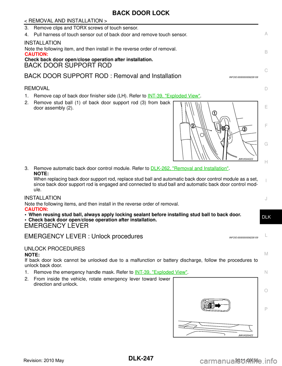
REMOVAL
1. Remove cap of back door finisher side (LH). Refer to INT-39, "Exploded View".
2. Remove stud ball (1) of back door support rod (3) from back door assembly (2).
3. Remove automatic back door control module. Refer to DLK-262, "
Removal and Installation".
NOTE:
When replacing back door support rod, replace stud ba ll and automatic back door control module as a set,
since back door support rod is engaged and connected to stud ball and automatic back door control mod-
ule.
INSTALLATION
Note the following items, and then install in the reverse order of removal.
CAUTION:
When reusing stud ball, always a pply locking sealant before installing stud ball to back door.
Check back door open/close opera tion after installation.
EMERGENCY LEVER
EMERGENCY LEVER : Unlock proceduresINFOID:0000000006226109
UNLOCK PROCEDURES
NOTE:
If back door lock cannot be unlocked due to a malfuncti on or battery discharge, follow the procedures to
unlock back door.
1. Remove the emergency handle mask. Refer to INT-39, "
Exploded View".
2. From inside the vehicle, rotate emergency lever toward lower direction and unlock.
JMKIA5442ZZ
JMKIA5264ZZ
Revision: 2010 May2011 QX56
Page 1788 of 5598
DLK-252
< REMOVAL AND INSTALLATION >
CAB MOUNTING INSULATOR
Drain brake fluid from brake line. Refer to BR-10, "Draining".
Release fuel pressure. Refer to EC-153, "
Work Procedure".
Disconnect both battery cables. Refer to PG-164, "
Removal and Installation".
Drain engine coolant from radiator. Refer to CO-8, "
Draining".
Discharge refrigerant from A/C circuit. Refer to HA-20, "
Recycle Refrigerant".
Drain power steering fluid from reservoir tank.
4. Remove parts relating to connection of body assembly and frame assembly. Tire and wheel: Refer to WT-64, "
Removal and Installation" (with TPMS).
Front fender protector (LH and RH): Refer to EXT-23, "
FENDER PROTECTOR : Removal and Installa-
tion".
Front bumper: Refer to EXT-13, "
Removal and Installation".
Radiator core support upper: Refer to DLK-220, "
Removal and Installation".
Fan shroud: Refer to CO-16, "
Removal and Installation".
Battery and battery case: Refer to PG-164, "
Removal and Installation".
Air cleaner case (upper and lower): Refer to EM-27, "
Removal and Installation".
Engine cover: Refer to EM-25, "
Removal and Installation".
Rear wheel house protector (LH and RH): EXT-24, "
REAR WHEEL HOUSE PROTECTOR : Removal
and Installation".
Rear bumper: Refer to EXT-17, "
Removal and Installation".
Fuel filler tube: Remove to FL-8, "
Exploded View".
Spare tire
Towing hook bracket.
5. Separate parts relating to connection of body assembly and frame assembly. Vehicle front
Disconnect ICC sensor connector. (models with ICC) Refer to CCS-176, "
Removal and Installation".
Remove radiator upper hose and radiator lower hose from radiator assembly. Refer to CO-13,
"Exploded View".
Remove A/T fluid cooler hose B and A/T fluid cooler hose E from A/T fluid cooler tubes. Refer to TM-
202, "Exploded View".
Remove power steering return hose from oil cooler, and then power steering return hose clamp bolt from frame assembly. Refer to ST-54, "
Exploded View".
Remove power steering suction hose from reservoir tank. Refer to ST-54, "
Exploded View".
CAUTION:
Never spill power steering fluid in engine room.
Remove A/C low-presser flexible hose from A/C low-presser pipe. Refer to HA-35, "
LOW-PRESSURE
FLEXIBLE HOSE : Removal and Installation".
Remove A/C hi-presser flexible hose from condenser. Refer to HA-34, "
HIGH-PRESSURE FLEXIBLE
HOSE : Removal and Installation".
Remove all engine Control Harness connectors, har ness clips and others that are connected to the
body assembly side of the engine room. (engine room LH and RH side). Refer to PG-148, "
Engine Con-
trol Harness".
NOTE:
Separate harness connectors from ECM (engine control module). Refer to EC-10, "
General Precau-
tions".
CAUTION:
When pulling out harnesses, never damage harnesses or connectors.
After temporarily securing connectors, cover th em with vinyl or similar material to protect
against adhesion of foreign materials.
Disconnect engine room harness connectors and remo ve harness clips from engine assembly (engine
RH side). Refer to PG-146, "
Engine Room Harness".
Remove heater hoses from front water outlet tube (engine room RH side). Refer to HA-33, "
Exploded
View".
Disconnect front wheel sensor connectors (LH and RH). Refer to BRC-134, "
FRONT WHEEL SENSOR
: Exploded View".
Disconnect fuel feed tube and EVAP hos e (front wheel well LH side).
Remove steering lower shaft from steering gear side assembly. Refer to ST-37, "
Removal and Installa-
tion"
CAUTION:
Spiral cable may be cut if steering wheel turns while separating steering column assembly and
steering gear assembly.
Revision: 2010 May2011 QX56
Page 1796 of 5598

DLK-260
< REMOVAL AND INSTALLATION >
INTELLIGENT KEY BATTERY
INTELLIGENT KEY BATTERY
Removal and InstallationINFOID:0000000006226127
1. Release the lock knob at the back of the Intelligent Key and remove the mechanical key.
2. Insert a flat-blade screwdriver (A) wrapped with a cloth into the slit of the corner and twist it to separate the upper part from the
lower part.
CAUTION:
Do not touch the circuit board or battery terminal.
The key fob is water-resistant. However, if it does get wet,immediately wipe it dry.
3. Replace the battery with new one.
4. Align the tips of the upper and lower parts, and then push them together until it is securely closed.
CAUTION:
When replacing battery, keep dirt, grease, and other for-
eign materials off the electrode contact area.
After replacing the battery, check that all Intelligent Key
functions work normally.
PIIB6221E
Battery replacement :Coin-type lithium battery
(CR2025)
PIIB6222E
Revision: 2010 May2011 QX56
Page 1803 of 5598
DLN-1
TRANSMISSION & DRIVELINE
CEF
G H
I
J
K L
M
SECTION DLN
A
B
DLN
N
O P
CONTENTS
DRIVELINE
TRANSFER: ATX90A
PRECAUTION ................ ...............................
6
PRECAUTIONS .............................................. .....6
Precaution for Supplemental Restraint System
(SRS) "AIR BAG" and "SEAT BELT PRE-TEN-
SIONER" ............................................................. ......
6
Precaution Necessary for Steering Wheel Rota-
tion after Battery Disconnect .....................................
6
Service Notice or Precautions for Transfer ...............7
PREPARATION ............................................8
PREPARATION .............................................. .....8
Special Service Tools .......................................... ......8
Commercial Service Tools ........................................8
SYSTEM DESCRIPTION .............................10
COMPONENT PARTS ................................... ....10
Component Parts Location .................................. ....10
Component Description ...........................................11
Transfer Control Unit ...............................................11
Transfer Control Actuator ........................................11
Transfer Hi-Lo Position Sensor ...............................12
Transfer Rotary Position Sensor .............................12
Transfer Lock Position Sensor ................................12
Transfer Fluid Temperature Sensor ........................12
STRUCTURE AND OPERATION .......................13
Sectional View ..................................................... ....13
Torque Split Mechanism .........................................13
SYSTEM .............................................................18
4WD SYSTEM ...........................................................18
4WD SYSTEM : System De scription ......................18
4WD SYSTEM : Fail-Safe ......................... ..............20
DIAGNOSIS SYSTEM (TRANSFER CON-
TROL UNIT) .................................................... ....
21
CONSULT-III Function ........................................ ....21
ECU DIAGNOSIS INFORMATION ..............24
TRANSFER CONTROL UNIT ...........................24
Reference Value .................................................. ....24
Fail-Safe ..................................................................28
DTC Inspection Priority Chart ..................................29
DTC Index ...............................................................29
WIRING DIAGRAM ......................................31
4WD SYSTEM .. ................................ .................31
Wiring Diagram .................................................... ....31
BASIC INSPECTION ...................................38
DIAGNOSIS AND REPAIR WORK FLOW .......38
Work Flow ............................................................ ....38
Diagnostic Work Sheet ............................................39
ADDITIONAL SERVICE WHEN REPLACING
TRANSFER CONTROL UNIT ...........................
41
Description ...............................................................41
Work Procedure .......................................................41
ADDITIONAL SERVICE WHEN REPLACING
TRANSFER ASSEMBLY ..................................
42
Description ...............................................................42
Work Procedure .......................................................42
TRANSFER LOCK POSITION SENSOR
LEARNING ....................................... .................
44
Description ........................................................... ....44
Work Procedure .......................................................44
TRANSFER ROTARY POSITION SENSOR
LEARNING ....................................... .................
46
Description ........................................................... ....46
Work Procedure .......................................................46
TRANSFER FLUID VISCOSITY LEARNING ....47
Description ...............................................................47
Revision: 2010 May2011 QX56