2011 INFINITI QX56 oil type
[x] Cancel search: oil typePage 2334 of 5598
![INFINITI QX56 2011 Factory Service Manual
EC-310
< DTC/CIRCUIT DIAGNOSIS >[VK56VD]
P0420, P0430 THREE
WAY CATALYST FUNCTION
6. Remove all ignition coil harness connectors to avoi d the electrical discharge from the ignition coils.
7. Remove INFINITI QX56 2011 Factory Service Manual
EC-310
< DTC/CIRCUIT DIAGNOSIS >[VK56VD]
P0420, P0430 THREE
WAY CATALYST FUNCTION
6. Remove all ignition coil harness connectors to avoi d the electrical discharge from the ignition coils.
7. Remove](/manual-img/42/57033/w960_57033-2333.png)
EC-310
< DTC/CIRCUIT DIAGNOSIS >[VK56VD]
P0420, P0430 THREE
WAY CATALYST FUNCTION
6. Remove all ignition coil harness connectors to avoi d the electrical discharge from the ignition coils.
7. Remove ignition coil and spark plug of the cylinder to be checked.
8. Crank engine for 5 seconds or more to remove combustion gas in the cylinder.
9. Connect spark plug and harness connector to ignition coil.
10. Fix ignition coil using a rope etc. with gap of 13 - 17 mm (0.52 - 0.66 in) between the edge of the spark plug and grounded metal
portion as shown in the figure.
11. Crank engine for approximately 3 seconds, and check whether spark is generated between the spark plug and the grounded
metal portion.
CAUTION:
Never place the spark plug and the ignition coil within 50
cm (19.7 in) each other. Be careful not to get an electrical
shock while checking, becau se the electrical discharge
voltage becomes 20 kV or more.
It might damage the ignition coil if the gap of more than 17 mm (0.66 in) is made.
NOTE:
When the gap is less than 13 mm (0.52 in), a spark might be generated even if the coil is malfunc-
tioning.
Is the inspection result normal?
YES >> GO TO 10.
NO >> GO TO 7.
7.CHECK FUNCTION OF IGNITION COIL-II
1. Turn ignition switch OFF.
2. Disconnect spark plug and connect a non-malfunctioning spark plug.
3. Crank engine for approximately 3 seconds, and rec heck whether spark is generated between the spark
plug and the grounded metal portion.
Is the inspection result normal?
YES >> GO TO 8.
NO >> Check ignition coil, power transistor and their circuits. Refer to EC-506, "
Diagnosis Procedure".
8.CHECK SPARK PLUG
Check the initial spark plug for fouling, etc.
Is the inspection result normal?
YES >> Replace spark plug(s) with standard type one(s). For spark plug type, refer to EM-132, "
Spark Plug".
NO >> Repair or clean spark plug. Then GO TO 9.
9.CHECK FUNCTION OF IGNITION COIL-III
1. Reconnect the initial spark plugs.
2. Crank engine for approximately 3 seconds, and rec heck whether spark is generated between the spark
plug and the grounded portion.
Is the inspection result normal?
YES >> INSPECTION END Spark should be generated.
JMBIA0066GB
Spark should be generated.
SEF156I
Spark should be generated.
Revision: 2010 May2011 QX56
Page 2335 of 5598
![INFINITI QX56 2011 Factory Service Manual
P0420, P0430 THREE WAY CATALYST FUNCTIONEC-311
< DTC/CIRCUIT DIAGNOSIS > [VK56VD]
C
D
E
F
G H
I
J
K L
M A
EC
NP
O
NO >> Replace spark plug(s) with standard type one(s). For spark plug type, refer to INFINITI QX56 2011 Factory Service Manual
P0420, P0430 THREE WAY CATALYST FUNCTIONEC-311
< DTC/CIRCUIT DIAGNOSIS > [VK56VD]
C
D
E
F
G H
I
J
K L
M A
EC
NP
O
NO >> Replace spark plug(s) with standard type one(s). For spark plug type, refer to](/manual-img/42/57033/w960_57033-2334.png)
P0420, P0430 THREE WAY CATALYST FUNCTIONEC-311
< DTC/CIRCUIT DIAGNOSIS > [VK56VD]
C
D
E
F
G H
I
J
K L
M A
EC
NP
O
NO >> Replace spark plug(s) with standard type one(s). For spark plug type, refer to
EM-132, "Spar k
Plug".
10.CHECK FUEL INJECTOR
1. Turn ignition switch OFF.
2. Remove fuel injector assembly. Refer to EM-49, "
Removal and Installation".
Keep fuel hose and all fuel injectors connected to fuel tube.
3. Disconnect all ignition coil harness connectors.
4. Reconnect all fuel injector harness connectors disconnected.
5. Turn ignition switch ON.
6. Check that fuel does not drip from fuel injector.
Does fuel drip from fuel injector?
YES >> Replace the fuel injector(s) from which fuel is dripping.
NO >> GO TO 11.
11 .CHECK INTERMITTENT INCIDENT
Refer to GI-40, "
Intermittent Incident".
Is the inspection result normal?
YES >> Replace three way catalyst assembly.
NO >> Repair or replace harness or connector.
Revision: 2010 May2011 QX56
Page 2578 of 5598
EM-16
< BASIC INSPECTION >
COMPRESSION PRESSURE
COMPRESSION PRESSURE
InspectionINFOID:0000000006289521
1. Warm up engine thoroughly. Then, stop it.
2. Release fuel pressure. Refer to EC-153, "
Work Procedure".
CAUTION:
If CONSULT-III is not used to release fuel pr essure leave the fuel pump fuse disconnected until
step 7.
3. Remove fuel pump fuse in IPDM E/R. NOTE:
For the fuse number, refer to EC-114, "
Wiring Diagram".
For the fuse arrangement, refer to PG-143, "
Fuse, Connector and Terminal Arrangement".
4. Remove engine cover. Refer to EM-25, "
Exploded View".
5. Remove ignition coil and spark plug from each cylinder. Refer to EM-29, "
Exploded View".
6. Connect engine tachometer (not required in use of CONSULT-III).
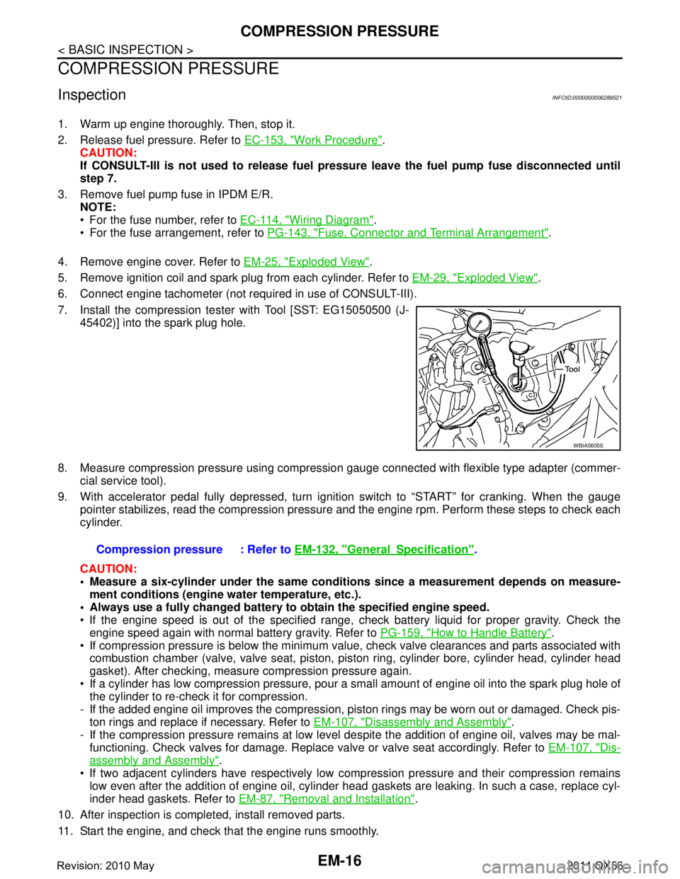
7. Install the compression tester with Tool [SST: EG15050500 (J- 45402)] into the spark plug hole.
8. Measure compression pressure using compressi on gauge connected with flexible type adapter (commer-
cial service tool).
9. With accelerator pedal fully depressed, turn ignition switch to “START” for cranking. When the gauge pointer stabilizes, read the compression pressure and the engine rpm. Perform these steps to check each
cylinder.
CAUTION:
Measure a six-cylinder under the same conditio ns since a measurement depends on measure-
ment conditions (engine water temperature, etc.).
Always use a fully changed battery to obtain the specified engine speed.
If the engine speed is out of the specified range, c heck battery liquid for proper gravity. Check the
engine speed again with normal battery gravity. Refer to PG-159, "
How to Handle Battery".
If compression pressure is below the minimum value, check valve clearances and parts associated with combustion chamber (valve, valve seat, piston, pi ston ring, cylinder bore, cylinder head, cylinder head
gasket). After checking, measure compression pressure again.
If a cylinder has low compression pressure, pour a small amount of engine oil into the spark plug hole of the cylinder to re-check it for compression.
- If the added engine oil improves the compression, pi ston rings may be worn out or damaged. Check pis-
ton rings and replace if necessary. Refer to EM-107, "
Disassembly and Assembly".
- If the compression pressure remains at low level despite the addition of engine oil, valves may be mal- functioning. Check valves for damage. Replace valve or valve seat accordingly. Refer to EM-107, "
Dis-
assembly and Assembly".
If two adjacent cylinders have respectively low co mpression pressure and their compression remains
low even after the addition of engine oil, cylinder head gaskets are leaking. In such a case, replace cyl-
inder head gaskets. Refer to EM-87, "
Removal and Installation".
10. After inspection is completed, install removed parts.
11. Start the engine, and check that the engine runs smoothly.
WBIA0605E
Compression pressure : Refer to EM-132, "GeneralSpecification".
Revision: 2010 May2011 QX56
Page 2581 of 5598
NOISE, VIBRATION AND HARSHNESS (NVH) TROUBLESHOOTINGEM-19
< SYMPTOM DIAGNOSIS >
C
DE
F
G H
I
J
K L
M A
EM
NP
O
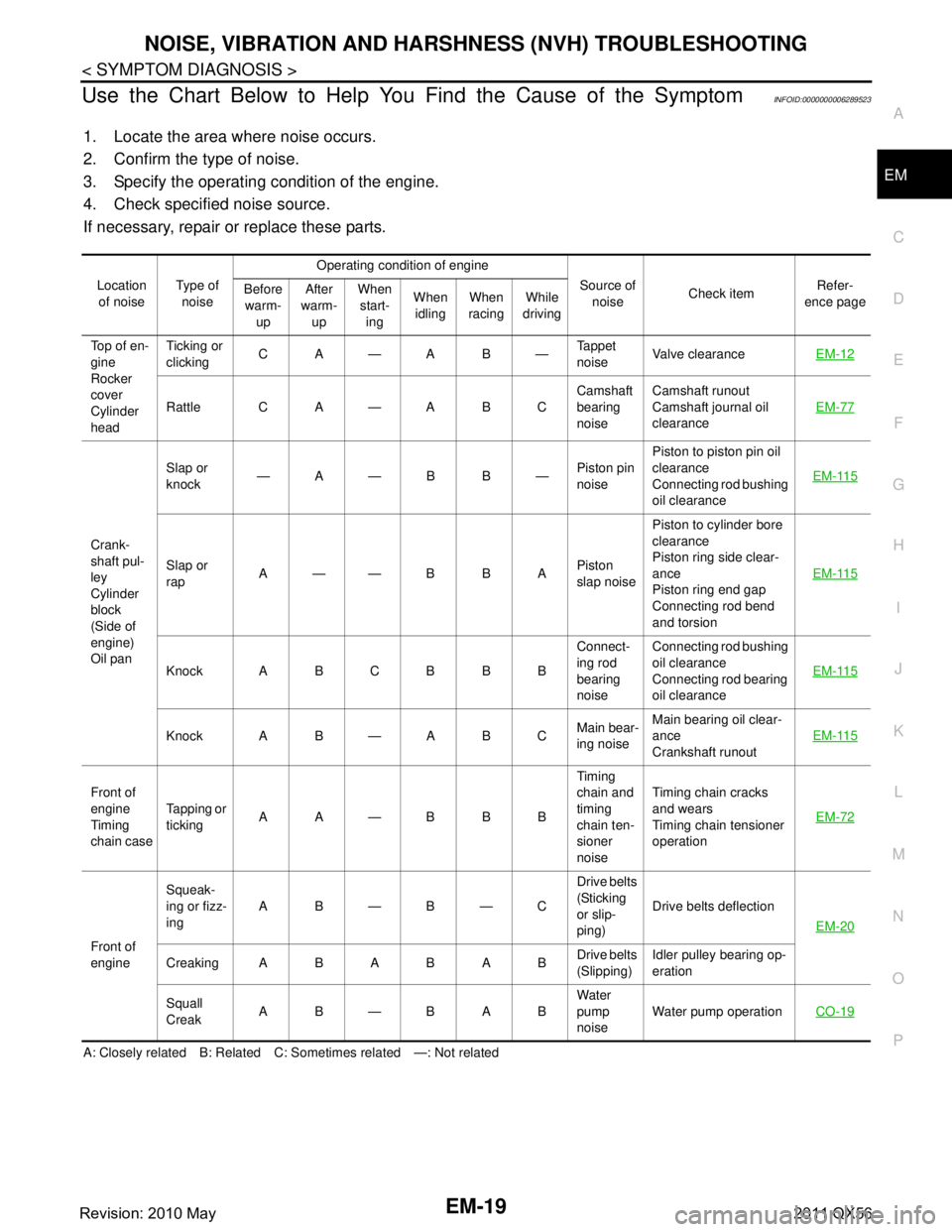
Use the Chart Below to Help You Find the Cause of the SymptomINFOID:0000000006289523
1. Locate the area where noise occurs.
2. Confirm the type of noise.
3. Specify the operating condition of the engine.
4. Check specified noise source.
If necessary, repair or replace these parts.
A: Closely related B: Related C: Sometimes related —: Not related Location
of noise Type of
noise Operating condition of engine
Source of noise Check item Refer-
ence page
Before
warm- up After
warm- up When
start- ing When
idling When
racing While
driving
Top of en-
gine
Rocker
cover
Cylinder
head Ticking or
clicking
CA—AB— Tappet
noiseValve clearance
EM-12
Rattle C A — A B C Camshaft
bearing
noiseCamshaft runout
Camshaft journal oil
clearance
EM-77
Crank-
shaft pul-
ley
Cylinder
block
(Side of
engine)
Oil panSlap or
knock
—A—B B—
Piston pin
noisePiston to piston pin oil
clearance
Connecting rod bushing
oil clearance
EM-115
Slap or
rap
A——B B A
Piston
slap noisePiston to cylinder bore
clearance
Piston ring side clear-
ance
Piston ring end gap
Connecting rod bend
and torsion
EM-115
Knock A B C B B B
Connect-
ing rod
bearing
noiseConnecting rod bushing
oil clearance
Connecting rod bearing
oil clearance
EM-115
Knock A B — A B C
Main bear-
ing noiseMain bearing oil clear-
ance
Crankshaft runout
EM-115
Front of
engine
Timing
chain caseTapping or
ticking
AA—BBB Timing
chain and
timing
chain ten-
sioner
noiseTiming chain cracks
and wears
Timing chain tensioner
operation
EM-72
Front of
engineSqueak-
ing or fizz-
ing
AB—B—C Drive belts
(Sticking
or slip-
ping)Drive belts deflection
EM-20
CreakingABABAB Drive belts
(Slipping)Idler pulley bearing op-
eration
Squall
Creak AB—BAB Water
pump
noiseWater pump operation
CO-19
Revision: 2010 May2011 QX56
Page 2586 of 5598
EM-24
< PERIODIC MAINTENANCE >
SPARK PLUG
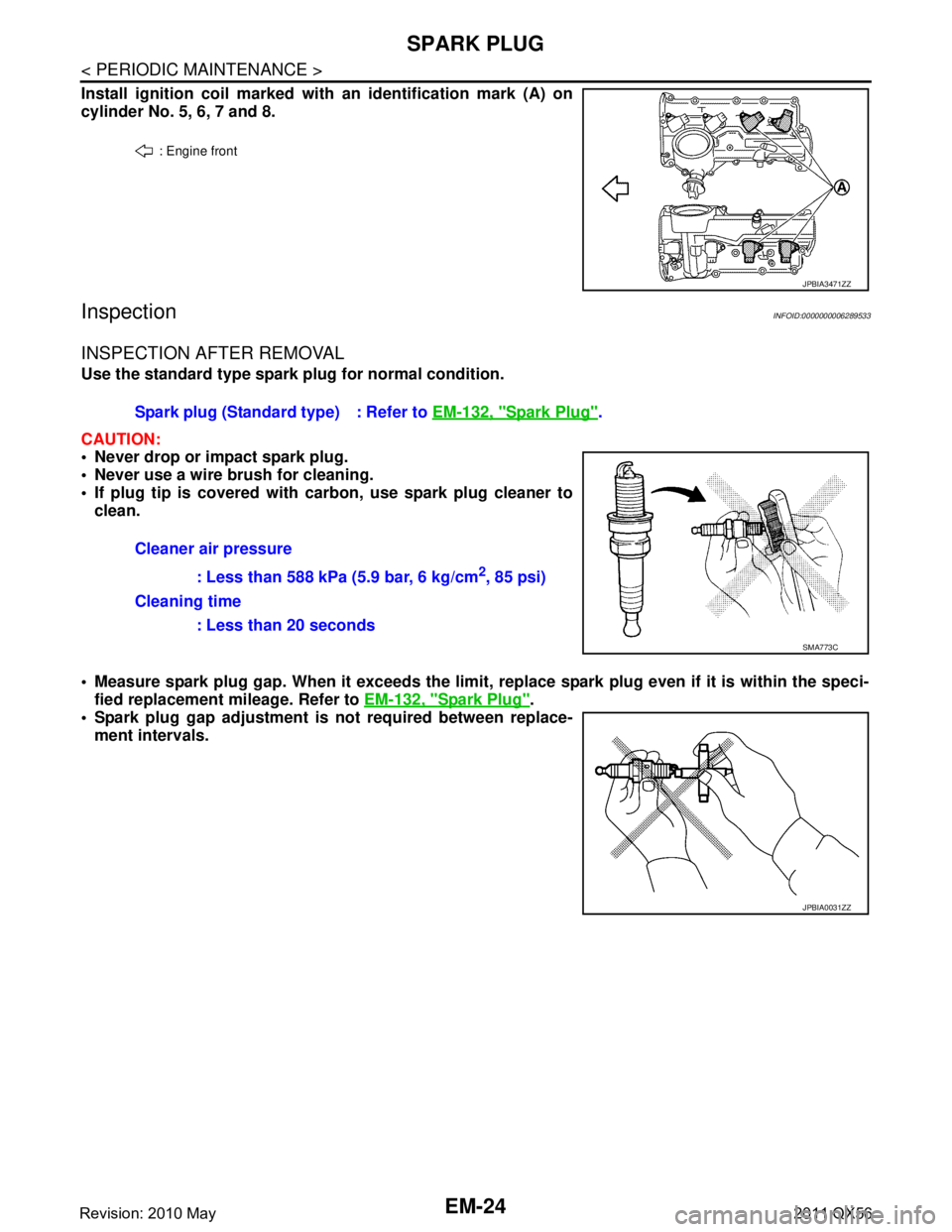
Install ignition coil marked with an identification mark (A) on
cylinder No. 5, 6, 7 and 8.
InspectionINFOID:0000000006289533
INSPECTION AFTER REMOVAL
Use the standard type spark plug for normal condition.
CAUTION:
Never drop or impact spark plug.
Never use a wire brush for cleaning.
If plug tip is covered with carbon, use spark plug cleaner to clean.
Measure spark plug gap. When it exceeds the limit, replace spark plug even if it is within the speci-
fied replacement mileage. Refer to EM-132, "
Spark Plug".
Spark plug gap adjustment is not required between replace-
ment intervals.
: Engine front
JPBIA3471ZZ
Spark plug (Standard type) : Refer to EM-132, "Spark Plug".
Cleaner air pressure : Less than 588 kPa (5.9 bar, 6 kg/cm
2, 85 psi)
Cleaning time : Less than 20 seconds
SMA773C
JPBIA0031ZZ
Revision: 2010 May2011 QX56
Page 2621 of 5598
OIL PAN (UPPER)EM-59
< REMOVAL AND INSTALLATION >
C
DE
F
G H
I
J
K L
M A
EM
NP
O
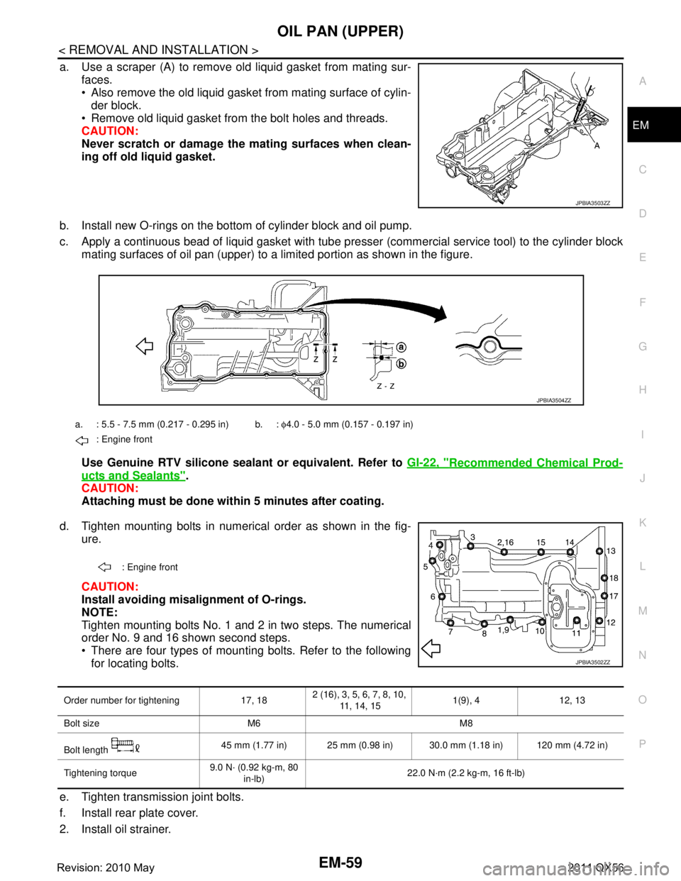
a. Use a scraper (A) to remove old liquid gasket from mating sur-
faces.
Also remove the old liquid gasket from mating surface of cylin-der block.
Remove old liquid gasket from the bolt holes and threads.
CAUTION:
Never scratch or damage th e mating surfaces when clean-
ing off old liquid gasket.
b. Install new O-rings on the bottom of cylinder block and oil pump.
c. Apply a continuous bead of liquid gasket with tube pre sser (commercial service tool) to the cylinder block
mating surfaces of oil pan (upper) to a limited portion as shown in the figure.
Use Genuine RTV silicone sealant or equivalent. Refer to GI-22, "
Recommended Chemical Prod-
ucts and Sealants".
CAUTION:
Attaching must be done with in 5 minutes after coating.
d. Tighten mounting bolts in numerical order as shown in the fig- ure.
CAUTION:
Install avoiding misal ignment of O-rings.
NOTE:
Tighten mounting bolts No. 1 and 2 in two steps. The numerical
order No. 9 and 16 shown second steps.
There are four types of mounting bolts. Refer to the following for locating bolts.
e. Tighten transmission joint bolts.
f. Install rear plate cover.
2. Install oil strainer.
JPBIA3503ZZ
a. : 5.5 - 7.5 mm (0.217 - 0.295 in) b. : φ4.0 - 5.0 mm (0.157 - 0.197 in)
: Engine front
JPBIA3504ZZ
: Engine front
JPBIA3502ZZ
Order number for tightening 17, 18 2 (16), 3, 5, 6, 7, 8, 10,
11, 14, 15 1(9), 4 12, 13
Bolt size M6 M8
Bolt length 45 mm (1.77 in) 25 mm (0.98 in) 30.0 mm (1.18 in) 120 mm (4.72 in)
Tightening torque 9.0 N· (0.92 kg-m, 80
in-lb) 22.0 N·m (2.2 kg-m, 16 ft-lb)
Revision: 2010 May2011 QX56
Page 2632 of 5598
EM-70
< REMOVAL AND INSTALLATION >
TIMING CHAIN
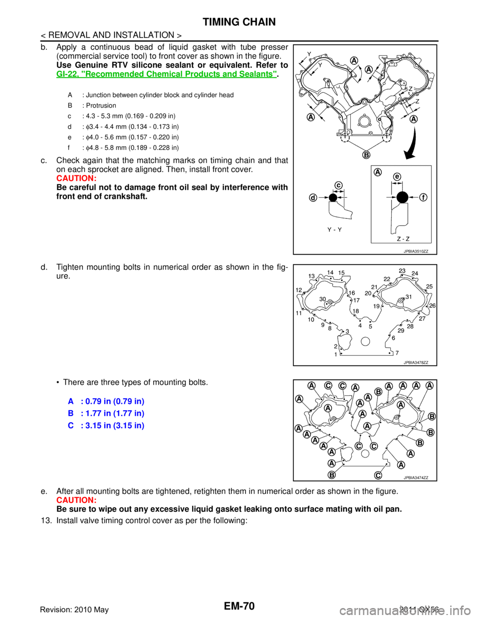
b. Apply a continuous bead of liquid gasket with tube presser(commercial service tool) to front cover as shown in the figure.
Use Genuine RTV silicone seal ant or equivalent. Refer to
GI-22, "
Recommended Chemical Products and Sealants".
c. Check again that the matching marks on timing chain and that on each sprocket are aligned. Then, install front cover.
CAUTION:
Be careful not to damage front oil seal by interference with
front end of crankshaft.
d. Tighten mounting bolts in numerical order as shown in the fig- ure.
There are three types of mounting bolts.
e. After all mounting bolts are tightened, retighten t hem in numerical order as shown in the figure.
CAUTION:
Be sure to wipe out any excessive liquid gasket leaking onto surface mating with oil pan.
13. Install valve timing control cover as per the following:
A : Junction between cylinder block and cylinder head
B : Protrusion
c : 4.3 - 5.3 mm (0.169 - 0.209 in)
d: φ3.4 - 4.4 mm (0.134 - 0.173 in)
e: φ4.0 - 5.6 mm (0.157 - 0.220 in)
f: φ4.8 - 5.8 mm (0.189 - 0.228 in)
JPBIA3510ZZ
JPBIA3478ZZ
A : 0.79 in (0.79 in)
B : 1.77 in (1.77 in)
C : 3.15 in (3.15 in)
JPBIA3474ZZ
Revision: 2010 May2011 QX56
Page 2665 of 5598

ENGINE STAND SETTINGEM-103
< UNIT DISASSEMBLY AND ASSEMBLY >
C
DE
F
G H
I
J
K L
M A
EM
NP
O
UNIT DISASSEMBLY AND ASSEMBLY
ENGINE STAND SETTING
SettingINFOID:0000000006289579
NOTE:
Explained here is how to disassemble with engine stand s
upporting transmission surface. When using a differ-
ent type of engine stand, note the difference in the steps, etc.
1. Remove the engine assembly from the vehicle. Refer to EM-98, "
Exploded View".
2. Remove crankshaft pulley. Refer to EM-96, "
FRONT OIL SEAL : Removal and Installation".
NOTE:
The drive plate is fixed with a ring gear stopper [SST: KV10119200 (J-49277)]. Loosen the crankshaft pul-
ley mounting bolts before installing the engine stand.
3. Remove the parts that may restrict installation of engine to a widely used engine stand. Fix crankshaft with a ring gear stopper [SST: KV10119200 (J-49277)]. Loosen drive plate mounting bolt
with power tool.
Check for deformation or damage of drive plate. Refer to EM-115, "
Inspection".
NOTE:
The procedure is described assuming that you us e a widely used engine stand holding the surface, to
which transmission is installed.
4. Remove pilot converter using the pilot bushing puller (commercial service tool), if necessary.
5. Lift the engine with hoist to inst all it onto the widely used engine stand.
CAUTION:
Use an engine stand that has a load capacity [240 kg (529 lb) or more] large enough for supporting
the engine weight.
If the load capacity of the stand is not adequate, remove the following parts beforehand to reduce the potential risk of overturning the stand.
- Remove intake manifold. Refer to EM-30, "
Exploded View".
- Remove fuel injector and fuel tube assembly. Refer to EM-48, "
Exploded View".
- Remove ignition coil. Refer to EM-29, "
Exploded View".
- Remove rocker cover. Refer to EM-33, "
Exploded View".
- Remove exhaust manifold. Refer to EM-40, "
Exploded View".
- Other removable brackets. NOTE:
The figure shows an example of widely used engine stand (A)
that can hold mating surface of transmission with drive plate
removed.
CAUTION:
Before removing the hang ing chains, check the engine
stand is stable and there is no risk of overturning.
6. Drain engine oil. Refer to LU-8, "
Draining".
JPBIA0190ZZ
Revision: 2010 May2011 QX56