2011 INFINITI QX56 engine oil capacity
[x] Cancel search: engine oil capacityPage 3687 of 5598

ENGINE MAINTENANCEMA-17
< PERIODIC MAINTENANCE >
C
DE
F
G H
I
J
K L
M B
MA
N
O A
FUEL LINES : InspectionINFOID:0000000006394850
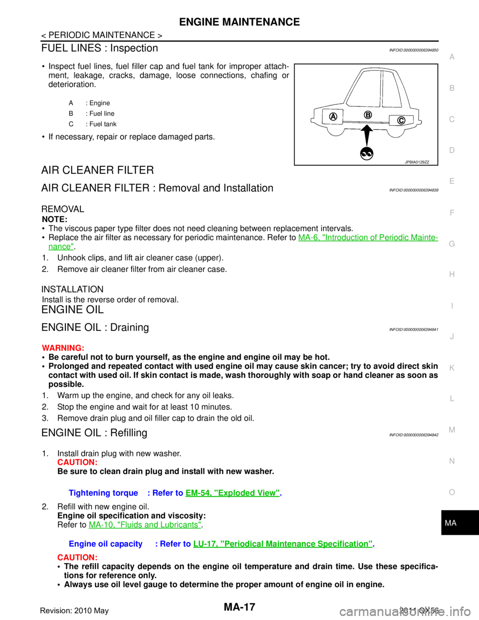
Inspect fuel lines, fuel filler cap and fuel tank for improper attach-
ment, leakage, cracks, damage, loose connections, chafing or
deterioration.
If necessary, repair or replace damaged parts.
AIR CLEANER FILTER
AIR CLEANER FILTER : Removal and InstallationINFOID:0000000006394838
REMOVAL
NOTE:
The viscous paper type filter does not need cleaning between replacement intervals.
Replace the air filter as necessary for periodic maintenance. Refer to MA-6, "
Introduction of Periodic Mainte-
nance".
1. Unhook clips, and lift air cleaner case (upper).
2. Remove air cleaner filter from air cleaner case.
INSTALLATION
Install is the reverse order of removal.
ENGINE OIL
ENGINE OIL : DrainingINFOID:0000000006394841
WARNING:
Be careful not to burn yourself, as th e engine and engine oil may be hot.
Prolonged and repeated contact with used engine oil may cau se skin cancer; try to avoid direct skin
contact with used oil. If skin contact is made, w ash thoroughly with soap or hand cleaner as soon as
possible.
1. Warm up the engine, and check for any oil leaks.
2. Stop the engine and wait for at least 10 minutes.
3. Remove drain plug and oil filler cap to drain the old oil.
ENGINE OIL : RefillingINFOID:0000000006394842
1. Install drain plug with new washer. CAUTION:
Be sure to clean drain plug and install with new washer.
2. Refill with new engine oil. Engine oil specificat ion and viscosity:
Refer to MA-10, "
Fluids and Lubricants".
CAUTION:
The refill capacity depends on the engine oi l temperature and drain time. Use these specifica-
tions for reference only.
Always use oil level gauge to determine the proper amount of engine oil in engine.
A : Engine
B : Fuel line
C : Fuel tank
JPBIA0129ZZ
Tightening torque : Refer to EM-54, "Exploded View".
Engine oil capacity : Refer to LU-17, "
Periodical Maintenance Specification".
Revision: 2010 May2011 QX56
Page 3695 of 5598

CHASSIS MAINTENANCEMA-25
< PERIODIC MAINTENANCE >
C
DE
F
G H
I
J
K L
M B
MA
N
O A
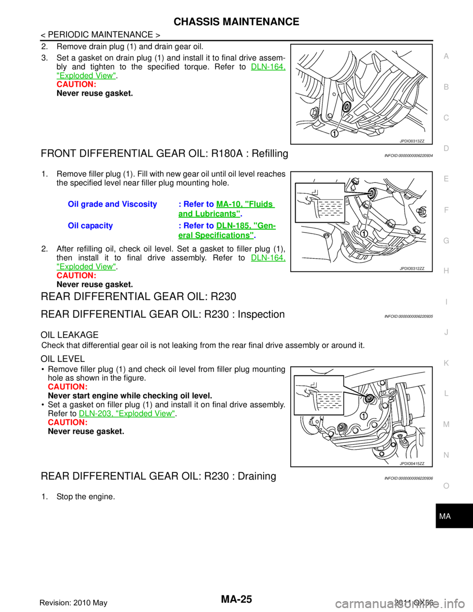
2. Remove drain plug (1) and drain gear oil.
3. Set a gasket on drain plug (1) and install it to final drive assem-
bly and tighten to the specified torque. Refer to DLN-164,
"Exploded View".
CAUTION:
Never reuse gasket.
FRONT DIFFERENTIAL GEAR OIL: R180A : RefillingINFOID:0000000006220934
1. Remove filler plug (1). Fill with new gear oil until oil level reaches
the specified level near filler plug mounting hole.
2. After refilling oil, check oil level. Set a gasket to filler plug (1), then install it to final drive assembly. Refer to DLN-164,
"Exploded View".
CAUTION:
Never reuse gasket.
REAR DIFFERENTIAL GEAR OIL: R230
REAR DIFFERENTIAL GEAR OIL: R230 : InspectionINFOID:0000000006220935
OIL LEAKAGE
Check that differential gear oil is not leaking fr om the rear final drive assembly or around it.
OIL LEVEL
Remove filler plug (1) and check oil level from filler plug mounting
hole as shown in the figure.
CAUTION:
Never start engine while checking oil level.
Set a gasket on filler plug (1) and install it on final drive assembly. Refer to DLN-203, "
Exploded View".
CAUTION:
Never reuse gasket.
REAR DIFFERENTIAL GEAR OIL: R230 : DrainingINFOID:0000000006220936
1. Stop the engine.
JPDID0313ZZ
Oil grade and Viscosity : Refer to MA-10, "Fluids
and Lubricants".
Oil capacity : Refer to DLN-185, "
Gen-
eral Specifications".
JPDID0312ZZ
JPDID0415ZZ
Revision: 2010 May2011 QX56
Page 3705 of 5598

SERVICE DATA AND SPECIFICATIONS (SDS)
MA-35
< SERVICE DATA AND SPECIFICATIONS (SDS)
C
D E
F
G H
I
J
K L
M B
MA
N
O A
SERVICE DATA AND SPECIFICATIONS (SDS)
SERVICE DATA AND SPECIFICATIONS (SDS)
DRIVE BELTS
DRIVE BELTS : Drive BeltsINFOID:0000000006394853
DRIVE BELT
ENGINE COOLANT
ENGINE COOLANT : Periodical Maintenance SpecificationINFOID:0000000006394856
ENGINE COOLANT CAPACITY (APPROXIMATELY)
Unit: (US qt, Imp qt)
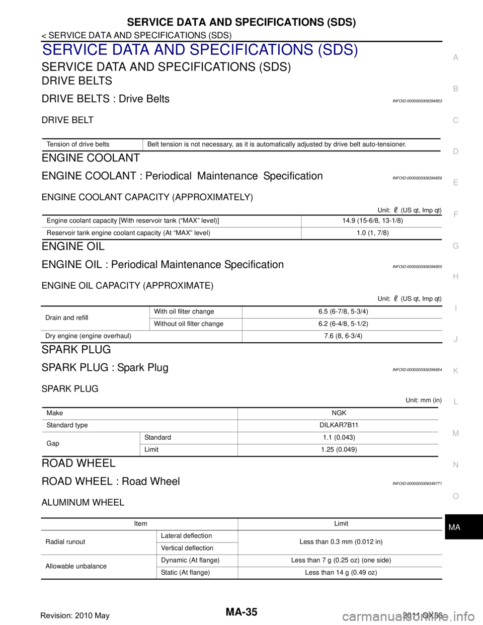
ENGINE OIL
ENGINE OIL : Periodical Maintenance SpecificationINFOID:0000000006394855
ENGINE OIL CAPACITY (APPROXIMATE)
Unit: (US qt, Imp qt)
SPARK PLUG
SPARK PLUG : Spark PlugINFOID:0000000006394854
SPARK PLUG
Unit: mm (in)
ROAD WHEEL
ROAD WHEEL : Road WheelINFOID:0000000006349771
ALUMINUM WHEEL
Tension of drive belts Belt tension is not necessary, as it is automatically adjusted by drive belt auto-tensioner.
Engine coolant capacity [With reservoir tank (“MAX” level)] 14.9 (15-6/8, 13-1/8)
Reservoir tank engine coolant capacity (At “MAX” level) 1.0 (1, 7/8)
Drain and refill
With oil filter change 6.5 (6-7/8, 5-3/4)
Without oil filter change 6.2 (6-4/8, 5-1/2)
Dry engine (engine overhaul) 7.6 (8, 6-3/4)
Make NGK
Standard type DILKAR7B11
Gap Standard 1.1 (0.043)
Limit 1.25 (0.049)
Item Limit
Radial runout Lateral deflection
Less than 0.3 mm (0.012 in)
Vertical deflection
Allowable unbalance Dynamic (At flange) Less than 7 g (0.25 oz) (one side)
Static (At flange) Less than 14 g (0.49 oz)
Revision: 2010 May2011 QX56
Page 5017 of 5598

ST-30
< PERIODIC MAINTENANCE >
POWER STEERING FLUID
PERIODIC MAINTENANCE
POWER STEERING FLUID
InspectionINFOID:0000000006225597
FLUID LEVEL
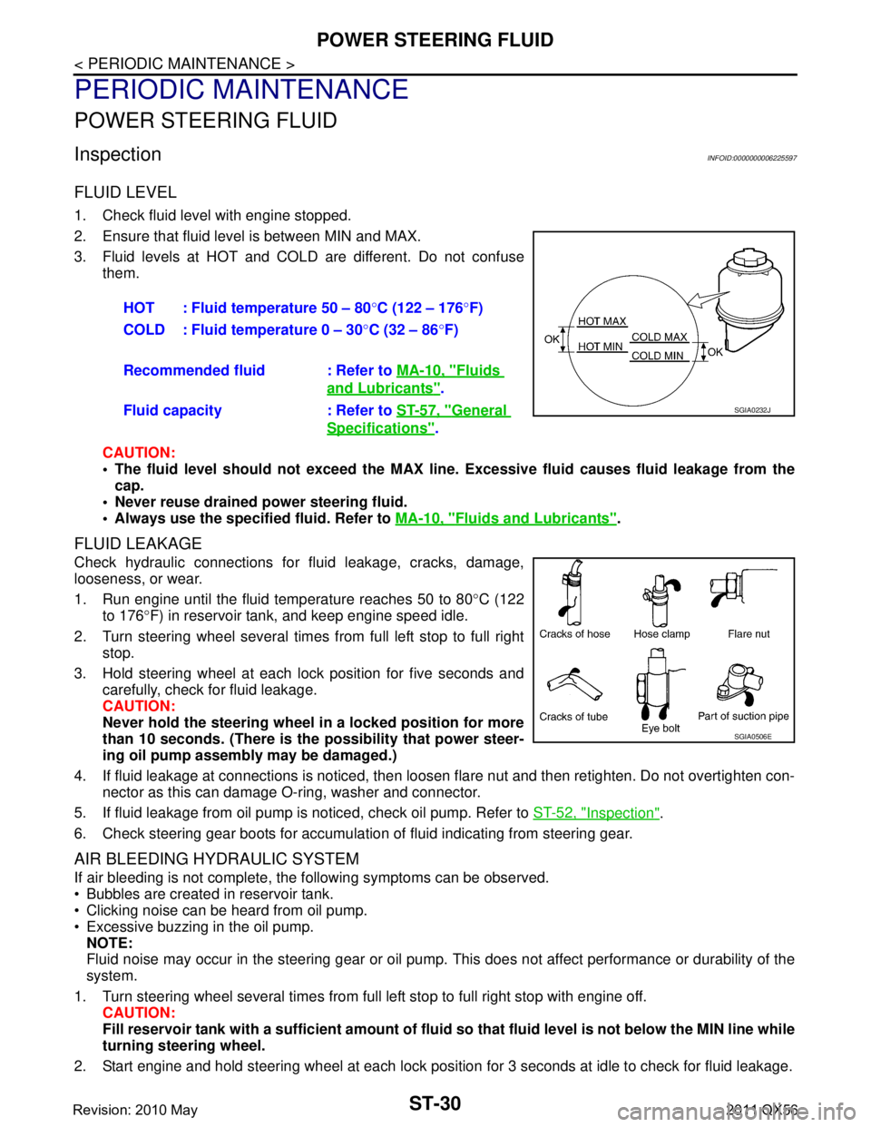
1. Check fluid level with engine stopped.
2. Ensure that fluid level is between MIN and MAX.
3. Fluid levels at HOT and COLD are different. Do not confuse
them.
CAUTION:
The fluid level should not exceed the MAX line. Excessive flui d causes fluid leakage from the
cap.
Never reuse drained power steering fluid.
Always use the specified fluid. Refer to MA-10, "
Fluids and Lubricants".
FLUID LEAKAGE
Check hydraulic connections for fluid leakage, cracks, damage,
looseness, or wear.
1. Run engine until the fluid temperature reaches 50 to 80 °C (122
to 176 °F) in reservoir tank, and keep engine speed idle.
2. Turn steering wheel several times from full left stop to full right stop.
3. Hold steering wheel at each lock position for five seconds and carefully, check for fluid leakage.
CAUTION:
Never hold the steering wheel in a locked position for more
than 10 seconds. (There is the possibility that power steer-
ing oil pump assembly may be damaged.)
4. If fluid leakage at connections is noticed, then loos en flare nut and then retighten. Do not overtighten con-
nector as this can damage O-ring, washer and connector.
5. If fluid leakage from oil pump is noticed, check oil pump. Refer to ST-52, "
Inspection".
6. Check steering gear boots for accumulation of fluid indicating from steering gear.
AIR BLEEDING HYDRAULIC SYSTEM
If air bleeding is not complete, the following symptoms can be observed.
Bubbles are created in reservoir tank.
Clicking noise can be heard from oil pump.
Excessive buzzing in the oil pump. NOTE:
Fluid noise may occur in the steering gear or oil pump. This does not affect performance or durability of the
system.
1. Turn steering wheel several times from full left stop to full right stop with engine off. CAUTION:
Fill reservoir tank with a sufficien t amount of fluid so that fluid level is not below the MIN line while
turning steering wheel.
2. Start engine and hold steering wheel at each lock position for 3 seconds at idle to check for fluid leakage.
HOT : Fluid temperature 50 – 80
°C (122 – 176 °F)
COLD : Fluid temperature 0 – 30 °C (32 – 86 °F)
Recommended fluid : Refer to MA-10, "
Fluids
and Lubricants".
Fluid capacity : Refer to ST-57, "
General
Specifications".
SGIA0232J
SGIA0506E
Revision: 2010 May2011 QX56
Page 5182 of 5598
![INFINITI QX56 2011 Factory Service Manual
TM-94
< BASIC INSPECTION >[7AT: RE7R01B]
A/T FLUID
A/T FLUID
ChangingINFOID:0000000006226791
CAUTION:
Use only Genuine NISSAN Matic S ATF. Never mix with other ATF.
Using ATF other than Genuine N INFINITI QX56 2011 Factory Service Manual
TM-94
< BASIC INSPECTION >[7AT: RE7R01B]
A/T FLUID
A/T FLUID
ChangingINFOID:0000000006226791
CAUTION:
Use only Genuine NISSAN Matic S ATF. Never mix with other ATF.
Using ATF other than Genuine N](/manual-img/42/57033/w960_57033-5181.png)
TM-94
< BASIC INSPECTION >[7AT: RE7R01B]
A/T FLUID
A/T FLUID
ChangingINFOID:0000000006226791
CAUTION:
Use only Genuine NISSAN Matic S ATF. Never mix with other ATF.
Using ATF other than Genuine NI
SSAN Matic S ATF will cause deteri oration in driveability and A/T
durability, and may damage the A/T, which is not covered by the INFINITI new vehicle limited war-
ranty.
When filling ATF, be careful not to scatte r heat generating parts such as exhaust.
1. Step 1
a. Install the O-ring (315268E000) (A) to the charging pipe (310811EA5A) (B).
2. Step 2
a. Use CONSULT-III to check that the ATF temperature is 40 °C (104 °F) or less.
b. Lift up the vehicle.
c. Remove the drain plug from the oil pan, and then drain the ATF.
d. When the ATF starts to drip, temporarily tighten the drain plug to the oil pan. NOTE:
Never replace drain plug and drain plug gasket with new ones yet.
e. Remove overflow plug from oil pan.
f. Install the charging pipe (A) to the overflow plug hole. CAUTION:
Tighten the charging pipe by hand.
g. Install the bucket pump hose (B) to the charging pipe. CAUTION:
Insert the bucket pump hose all the way to the end of the
charging pipe.
h. Fill approximately 3 liters (3-1/8 US qt, 2-5/8 lmp qt) of the ATF.
i. Remove the bucket pump hose to remove the charging pipe, and then temporarily tighten the overflow plug to the oil pan.
CAUTION:
Quickly perform the procedur e to avoid ATF leakage from
the oil pan.
j. Lift down the vehicle.
k. Start the engine and wait for approximately 3 minutes.
l. Stop the engine.
3. Step 3
a. Repeat “Step 2”.
4. Final Step
a. Use CONSULT-III to check that the ATF temperature is 40 °C (104 °F) or less.
b. Lift up the vehicle.
c. Remove the drain plug from the oil pan, and then drain the ATF.
Recommended fluid and fluid capacity : Refer to TM-296, "General Specification".
JSDIA1334ZZ
JSDIA1335ZZ
Revision: 2010 May2011 QX56
Page 5183 of 5598
![INFINITI QX56 2011 Factory Service Manual
A/T FLUIDTM-95
< BASIC INSPECTION > [7AT: RE7R01B]
C
EF
G H
I
J
K L
M A
B
TM
N
O P
d. When the ATF starts to drip, tighten the drain plug to the oil pan to the specified torque. Refer to TM-182,
"Ex INFINITI QX56 2011 Factory Service Manual
A/T FLUIDTM-95
< BASIC INSPECTION > [7AT: RE7R01B]
C
EF
G H
I
J
K L
M A
B
TM
N
O P
d. When the ATF starts to drip, tighten the drain plug to the oil pan to the specified torque. Refer to TM-182,
"Ex](/manual-img/42/57033/w960_57033-5182.png)
A/T FLUIDTM-95
< BASIC INSPECTION > [7AT: RE7R01B]
C
EF
G H
I
J
K L
M A
B
TM
N
O P
d. When the ATF starts to drip, tighten the drain plug to the oil pan to the specified torque. Refer to TM-182,
"Exploded View".
CAUTION:
Never reuse drain plug and drain plug gasket.
e. Remove overflow plug from oil pan.
f. Install the charging pipe (A) to the overflow plug hole. CAUTION:
Tighten the charging pipe by hand.
g. Install the bucket pump hose (B) to the charging pipe. CAUTION:
Insert the bucket pump hose all the way to the end of the
charging pipe.
h. Fill approximately 3 liters (3-1/8 US qt, 2-5/8 lmp qt) of the ATF.
i. Remove the bucket pump hose to remove the charging pipe, and then temporarily tighten the overflow plug to the oil pan.
CAUTION:
Quickly perform the procedure to avoid ATF leakage from
the oil pan.
j. Lift down the vehicle.
k. Start the engine.
l. Make the ATF temperature approximately 40 °C (104 °F).
NOTE:
The ATF level is greatly affected by the temperat ure. Always check the ATF temperature on “ATF TEMP
1” of “Data Monitor” using CONSULT-III.
m. Park vehicle on level surface and set parking brake.
n. Shift the selector lever through each gear pos ition. Leave selector lever in “P” position.
o. Lift up the vehicle when the ATF temperature reaches 40 °C (104 °F), and remove the overflow plug from
the oil pan.
CAUTION:
Perform “Step 4-o” with the engine at idle.
p. When the ATF starts to drip, tighten the overflow plug to the oil pan to the specified torque. Refer to TM-
182, "Exploded View".
CAUTION:
Never reuse overflow plug.
AdjustmentINFOID:0000000006226792
CAUTION:
Use only Genuine NISSAN Matic S ATF. Never mix with other ATF.
Using ATF other than Genuine NI SSAN Matic S ATF will cause deteri oration in driveability and A/T
durability, and may damage the A/T, which is not covered by the INFINITI new vehicle limited war-
ranty.
When filling ATF, be careful not to sca tter heat generating parts such as exhaust.
Always maintain the ATF temperature within between 35 °C (95 °F) and 45 °C (113 °F) while checking
with CONSULT-III when the ATF level adjustment is performed.
JSDIA1335ZZ
Recommended fluid and fluid capacity : Refer to TM-296, "General Specification".
Revision: 2010 May2011 QX56