2011 INFINITI QX56 body interior
[x] Cancel search: body interiorPage 3271 of 5598
INL-4
< SYSTEM DESCRIPTION >
COMPONENT PARTS
SYSTEM DESCRIPTION
COMPONENT PARTS
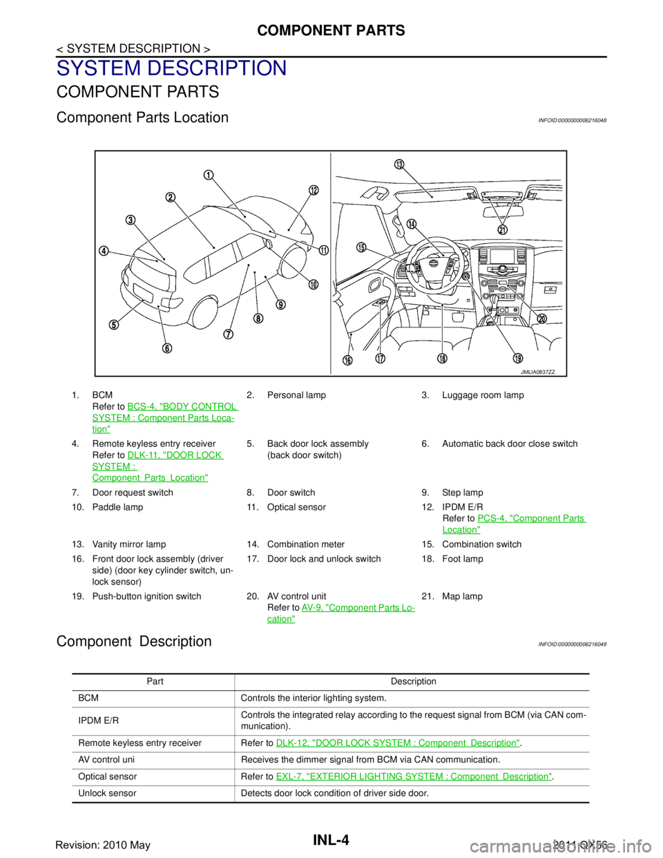
Component Parts LocationINFOID:0000000006216048
Component DescriptionINFOID:0000000006216049
1. BCMRefer to BCS-4, "
BODY CONTROL
SYSTEM : Componen t Parts Loca-
tion"
2. Personal lamp 3. Luggage room lamp
4. Remote keyless entry receiver Refer to DLK-11, "
DOOR LOCK
SYSTEM :
ComponentPartsLocation"
5. Back door lock assembly
(back door switch) 6. Automatic back door close switch
7. Door request switch 8. Door switch 9. Step lamp
10. Paddle lamp 11. Optical sensor 12. IPDM E/R Refer to PCS-4, "
Component Parts
Location"
13. Vanity mirror lamp 14. Combination meter 15. Combination switch
16. Front door lock assembly (driver
side) (door key cylinder switch, un-
lock sensor) 17. Door lock and unlock switch 18. Foot lamp
19. Push-button ignition switch 20. AV control unit Refer to AV- 9 , "
Component Parts Lo-
cation"
21. Map lamp
JMLIA0837ZZ
Part Description
BCM Controls the interior lighting system.
IPDM E/R Controls the integrated relay according to the request signal from BCM (via CAN com-
munication).
Remote keyless entry receiver Refer to DLK-12, "
DOOR LOCK SYSTEM : ComponentDescription".
AV control uni Receives the dimmer signal from BCM via CAN communication.
Optical sensor Refer to EXL-7, "
EXTERIOR LIGHTING SYSTEM : ComponentDescription".
Unlock sensor Detects door lock condition of driver side door.
Revision: 2010 May2011 QX56
Page 3279 of 5598
INL-12
< SYSTEM DESCRIPTION >
DIAGNOSIS SYSTEM (BCM)
DIAGNOSIS SYSTEM (BCM)
COMMON ITEM
COMMON ITEM : CONSULT-III Function (BCM - COMMON ITEM)INFOID:0000000006368143
APPLICATION ITEM
CONSULT-III performs the following functions via CAN communication with BCM.
SYSTEM APPLICATION
BCM can perform the following functions for each system.
NOTE:
It can perform the diagnosis modes except the following for all sub system selection items.
×: Applicable item
*: This item is indicated, but not used.
FREEZE FRAME DATA (FFD)
The BCM records the following vehicle condition at the time a particular DTC is detected, and displays on
CONSULT-III.
Diagnosis mode Function Description
Work Support Changes the setting for each system function.
Self Diagnostic Result Displays the diagnosis results judged by BCM. Refer to BCS-57, "
DTCIndex".
CAN Diag Support Monitor Monitors the reception status of CAN communication viewed from BCM. Refer to CONSULT-III opera-
tion manual.
Data Monitor The BCM input/output signals are displayed.
Active Test The signals used to activate ea ch device are forcibly supplied from BCM.
Ecu Identification The BCM part number is displayed.
Configuration Read and save the vehicle specification.
Write the vehicle specification when replacing BCM.
System Sub system selection item Diagnosis mode
Work Support Data Monitor Active Test
Door lock DOOR LOCK ×××
Rear window defogger REAR DEFOGGER ××
Warning chime BUZZER ××
Interior room lamp timer INT LAMP ×××
Exterior lamp HEAD LAMP ×××
Wiper and washer WIPER ×××
Turn signal and hazard warning lamps FLASHER ×××
— AIR CONDITONER* ××
Intelligent Key system
Engine start system INTELLIGENT KEY
×××
Combination switch COMB SW ×
Body control system BCM ×
IVIS IMMU ×××
Interior room lamp battery saver BATTERY SAVER ×××
Back door TRUNK ×
Vehicle security system THEFT ALM ×××
RAP system RETAINED PWR ×
Signal buffer system SIGNAL BUFFER ××
Revision: 2010 May2011 QX56
Page 3350 of 5598
INT-1
BODY INTERIOR
C
DE
F
G H
I
K L
M
SECTION INT
A
B
INT
N
O P
CONTENTS
INTERIOR
PRECAUTION ................ ...............................3
PRECAUTIONS .............................................. .....3
Precaution for Supplemental Restraint System
(SRS) "AIR BAG" and "SEAT BELT PRE-TEN-
SIONER" ............................................................. ......
3
Precaution Necessary for Steering Wheel Rota-
tion after Battery Disconnect .....................................
3
Precaution for Procedure without Cowl Top Cover ......4
Precaution for Work ..................................................4
PREPARATION ............................................5
PREPARATION .............................................. .....5
Special Service Tools .......................................... ......5
Commercial Service Tools ........................................5
CLIP LIST ............................................................6
Clip List ............................................................... ......6
SYMPTOM DIAGNOSIS ...............................7
SQUEAK AND RATTLE TROUBLE DIAG-
NOSES ........................ ........................................
7
Work Flow ........................................................... ......7
Inspection Procedure ................................................9
Diagnostic Worksheet .............................................11
REMOVAL AND INSTALLATION ...............13
FRONT DOOR FINISHER .............................. ....13
Exploded View .................................................... ....13
Removal and Installation .........................................14
REAR DOOR FINISHER ....................................16
Exploded View .................................................... ....16
Removal and Installation .........................................16
BODY SIDE TRIM ..............................................18
Exploded View .................................................... ....18
DASH SIDE FINISHER .......................................... ....18
DASH SIDE FINISHER : Removal and Installation
....
18
FRONT PILLAR GARNISH .................................... ....19
FRONT PILLAR GARNISH : Removal and Instal-
lation ........................................................................
19
BODY SIDE WELT ................................................. ....20
BODY SIDE WELT : Removal and Installation ........20
KICKING PLATE INNER ....................................... ....20
KICKING PLATE INNER : Removal and Installa-
tion ...........................................................................
20
KICKING PLATE OUTER ...................................... ....21
KICKING PLATE OUTER : Removal and Installa-
tion ...........................................................................
21
CENTER PILLAR LOWER GARNISH ................... ....22
CENTER PILLAR LOWER GARNISH : Removal
and Installation ........................................................
22
CENTER PILLAR UPPER GARNISH ........................22
CENTER PILLAR UPPER GARNISH : Removal
and Installation .................................................... ....
22
FLOOR TRIM ....................................................24
Exploded View .........................................................24
FRONT FLOOR CARPET ...................................... ....25
FRONT FLOOR CARPET : Removal and Installa-
tion ....................................................................... ....
25
REAR FLOOR CARPET ........................................ ....27
REAR FLOOR CARPET : Removal and Installa-
tion ...........................................................................
27
HEADLINING ....................................................28
Exploded View .........................................................28
Removal and Installation .........................................29
LUGGAGE FLOOR TRIM .................................33
Exploded View .........................................................33
Revision: 2010 May2011 QX56
Page 3391 of 5598
IP-1
BODY INTERIOR
C
DE
F
G H
I
K L
M
SECTION IP
A
B
IP
N
O P
CONTENTS
INSTRUMENT PANEL
PRECAUTION ................ ...............................2
PRECAUTIONS .............................................. .....2
Precaution for Supplemental Restraint System
(SRS) "AIR BAG" and "SEAT BELT PRE-TEN-
SIONER" ............................................................. ......
2
Precaution Necessary for Steering Wheel Rota-
tion after Battery Disconnect .....................................
2
Service ......................................................................3
PREPARATION ............................................4
PREPARATION .............................................. .....4
Special Service Tools ........................................ ......4
Commercial Service Tools .......................................4
CLIP LIST ............................................................6
Clip List ............................................................... ......6
SYMPTOM DIAGNOSIS ...............................7
SQUEAK AND RATTLE TROUBLE DIAG-
NOSES ...............................................................
7
Work Flow ............................................................ .....7
Inspection Procedure ................................................9
Diagnostic Worksheet ..............................................11
REMOVAL AND INSTALLATION ...............13
INSTRUMENT PANEL ASSEMBLY .................13
Exploded View ..................................................... ....13
Removal and Installation .........................................14
CENTER CONSOLE ASSEMBLY ....................23
Exploded View .........................................................23
Removal and Installation .........................................25
Disassembly and Assembly .....................................27
REAR CONSOLE ASSEMBLY .........................29
Exploded View .........................................................29
Removal and Installation .........................................29
Disassembly and Assembly .....................................30
Revision: 2010 May2011 QX56
Page 3880 of 5598
![INFINITI QX56 2011 Factory Service Manual
PCS
DIAGNOSIS SYSTEM (BCM)PCS-39
< SYSTEM DESCRIPTION > [POWER DISTRIBUTION SYSTEM]
C
D
E
F
G H
I
J
K L
B A
O P
N
DIAGNOSIS SYSTEM (BCM)
COMMON ITEM
COMMON ITEM : CONSULT-III Fu
nction (BCM - COMMON INFINITI QX56 2011 Factory Service Manual
PCS
DIAGNOSIS SYSTEM (BCM)PCS-39
< SYSTEM DESCRIPTION > [POWER DISTRIBUTION SYSTEM]
C
D
E
F
G H
I
J
K L
B A
O P
N
DIAGNOSIS SYSTEM (BCM)
COMMON ITEM
COMMON ITEM : CONSULT-III Fu
nction (BCM - COMMON](/manual-img/42/57033/w960_57033-3879.png)
PCS
DIAGNOSIS SYSTEM (BCM)PCS-39
< SYSTEM DESCRIPTION > [POWER DISTRIBUTION SYSTEM]
C
D
E
F
G H
I
J
K L
B A
O P
N
DIAGNOSIS SYSTEM (BCM)
COMMON ITEM
COMMON ITEM : CONSULT-III Fu
nction (BCM - COMMON ITEM)INFOID:0000000006376369
APPLICATION ITEM
CONSULT-III performs the following functions via CAN communication with BCM.
SYSTEM APPLICATION
BCM can perform the following functions for each system.
NOTE:
It can perform the diagnosis modes except the following for all sub system selection items.
×: Applicable item
*: This item is indicated, but not used.
FREEZE FRAME DATA (FFD)
The BCM records the following vehicle condition at the time a particular DTC is detected, and displays on
CONSULT-III.
Diagnosis mode Function Description
Work Support Changes the setting for each system function.
Self Diagnostic Result Displays the diagnosis results judged by BCM. Refer to BCS-57, "
DTCIndex".
CAN Diag Support Monitor Monitors the reception status of CAN communication viewed from BCM. Refer to CONSULT-III opera-
tion manual.
Data Monitor The BCM input/output signals are displayed.
Active Test The signals used to activate each device are forcibly supplied from BCM.
Ecu Identification The BCM part number is displayed.
Configuration Read and save the vehicle specification.
Write the vehicle specification when replacing BCM.
System Sub system selection item Diagnosis mode
Work Support Data Monitor Active Test
Door lock DOOR LOCK ×××
Rear window defo gger REAR DEFOGGER ××
Warning chime BUZZER ××
Interior room lamp timer INT LAMP ×××
Exterior lamp HEAD LAMP ×××
Wiper and washer WIPER ×××
Turn signal and hazard warning lamps FLASHER ×××
— AIR CONDITONER* ××
Intelligent Key system
Engine start system INTELLIGENT KEY
×××
Combination switch COMB SW ×
Body control system BCM ×
IVIS IMMU ×××
Interior room lamp battery saver BATTERY SAVER ×××
Back door TRUNK ×
Vehicle security system THEFT ALM ×××
RAP system RETAINED PWR ×
Signal buffer system SIGNAL BUFFER ××
Revision: 2010 May2011 QX56
Page 4096 of 5598
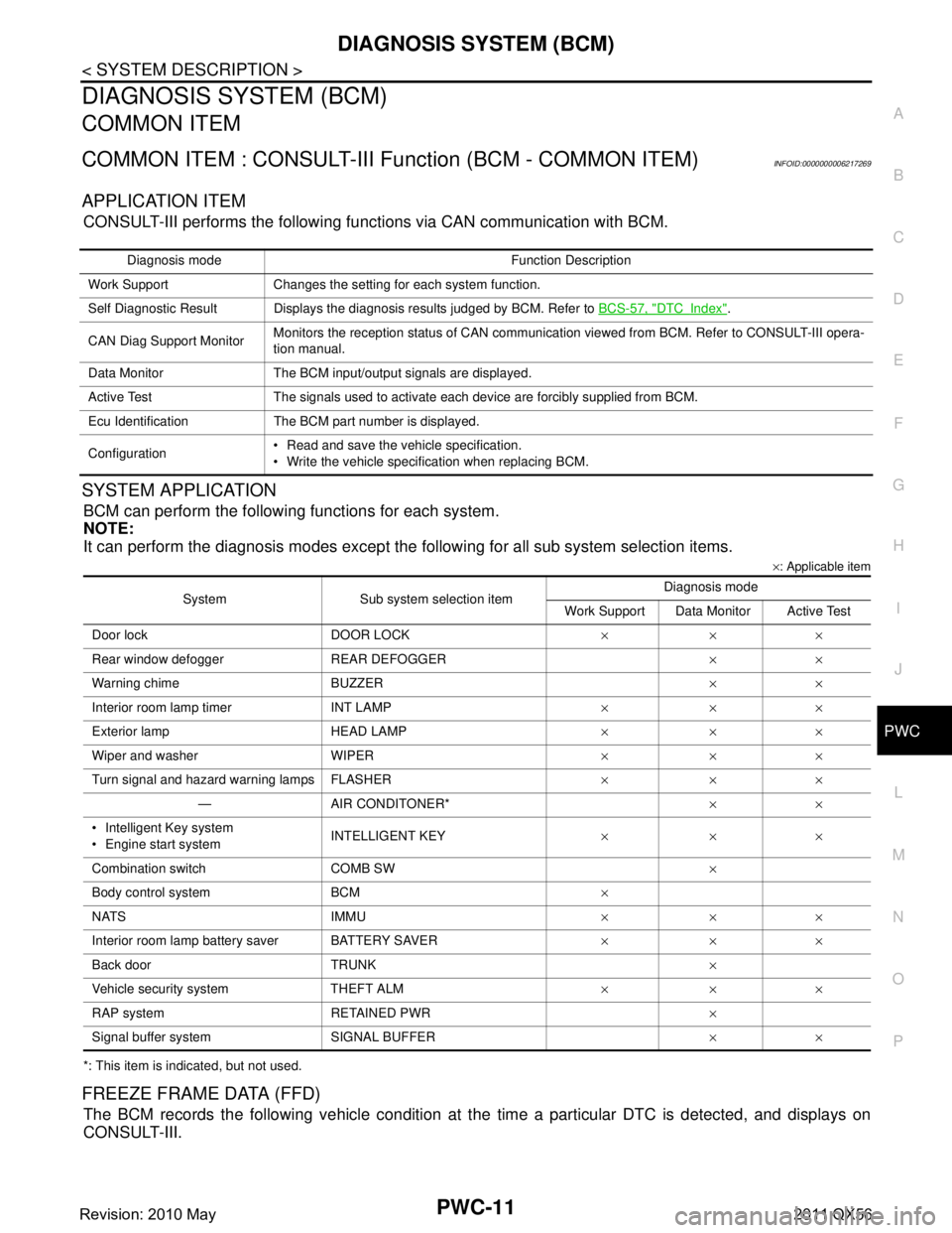
DIAGNOSIS SYSTEM (BCM)PWC-11
< SYSTEM DESCRIPTION >
C
DE
F
G H
I
J
L
M A
B
PWC
N
O P
DIAGNOSIS SYSTEM (BCM)
COMMON ITEM
COMMON ITEM : CONSULT-III Fu nction (BCM - COMMON ITEM)INFOID:0000000006217269
APPLICATION ITEM
CONSULT-III performs the following functions via CAN communication with BCM.
SYSTEM APPLICATION
BCM can perform the following functions for each system.
NOTE:
It can perform the diagnosis modes except the following for all sub system selection items.
×: Applicable item
*: This item is indicated, but not used.
FREEZE FRAME DATA (FFD)
The BCM records the following vehicle condition at the time a particular DTC is detected, and displays on
CONSULT-III.
Diagnosis mode Function Description
Work Support Changes the setting for each system function.
Self Diagnostic Result Displays the diagnosis results judged by BCM. Refer to BCS-57, "
DTCIndex".
CAN Diag Support Monitor Monitors the reception status of CAN communication viewed from BCM. Refer to CONSULT-III opera-
tion manual.
Data Monitor The BCM input/output signals are displayed.
Active Test The signals used to activate each device are forcibly supplied from BCM.
Ecu Identification The BCM part number is displayed.
Configuration Read and save the vehicle specification.
Write the vehicle specification when replacing BCM.
System Sub system selection item Diagnosis mode
Work Support Data Monitor Active Test
Door lock DOOR LOCK ×××
Rear window defo gger REAR DEFOGGER ××
Warning chime BUZZER ××
Interior room lamp timer INT LAMP ×××
Exterior lamp HEAD LAMP ×××
Wiper and washer WIPER ×××
Turn signal and hazard warning lamps FLASHER ×××
— AIR CONDITONER* ××
Intelligent Key system
Engine start system INTELLIGENT KEY
×××
Combination switch COMB SW ×
Body control system BCM ×
NATS IMMU ×××
Interior room lamp battery saver BATTERY SAVER ×××
Back door TRUNK ×
Vehicle security system THEFT ALM ×××
RAP system RETAINED PWR ×
Signal buffer system SIGNAL BUFFER ××
Revision: 2010 May2011 QX56
Page 4460 of 5598
SE-1
BODY INTERIOR
C
DE
F
G H
I
K L
M
SECTION SE
A
B
SE
N
O P
CONTENTS
SEAT
PRECAUTION ................ ...............................4
PRECAUTIONS .............................................. .....4
Precaution for Supplemental Restraint System
(SRS) "AIR BAG" and "SEAT BELT PRE-TEN-
SIONER" ............................................................. ......
4
Service Notice ...........................................................4
Precaution for Work ..................................................4
PREPARATION ............................................6
PREPARATION .............................................. .....6
Commercial Service Tool .................................... ......6
CLIP LIST ............................................................7
Clip List ............................................................... ......7
SYSTEM DESCRIPTION ..............................8
COMPONENT PARTS ................................... .....8
POWER SEAT SYSTEM .............................................8
POWER SEAT SYSTEM : Component Parts Lo-
cation ................................................................... ......
8
POWER SEAT SYSTEM : Component Descrip-
tion ...................................................................... ......
8
LUMBAR SUPPORT SYSTEM .............................. ......8
LUMBAR SUPPORT SYSTEM : Component
Parts Location ..................................................... ......
9
LUMBAR SUPPORT SYSTEM : Component De-
scription .....................................................................
9
SECOND SEAT POWER UNLOCK SYSTEM ....... ......9
SECOND SEAT POWER UNLOCK SYSTEM :
Component Parts Location ......................................
10
SECOND SEAT POWER UNLOCK SYSTEM :
Component Description ...........................................
10
THIRD SEAT SEATBACK POWER FOLDING
SYSTEM ................................................................ ....
10
THIRD SEAT SEATBACK POWER FOLDING
SYSTEM : Component Parts Location ....................
11
THIRD SEAT SEATBACK POWER FOLDING
SYSTEM : Component Description ..................... ....
11
FRONT HEATED SEAT SYSTEM ......................... ....12
FRONT HEATED SEAT SYSTEM : Component
Parts Location ..........................................................
12
FRONT HEATED SEAT SYSTEM : Component
Description ...............................................................
12
SECOND HEATED SEAT SYSTEM ...................... ....13
SECOND HEATED SEAT SYSTEM : Component
Parts Location ..........................................................
13
SECOND HEATED SEAT SYSTEM : Component
Description ...............................................................
13
CLIMATE CONTROLLED SEAT SYSTEM ...............13
CLIMATE CONTROLLED SEAT SYSTEM : Com-
ponent Parts Location .......................................... ....
14
CLIMATE CONTROLLED SEAT SYSTEM : Com-
ponent Description ...................................................
14
SYSTEM ............................................................16
POWER SEAT SYSTEM ....... .....................................16
POWER SEAT SYSTEM : Syst em Description .......16
LUMBAR SUPPORT SYSTEM .............................. ....16
LUMBAR SUPPORT SYSTEM : System Descrip-
tion ...........................................................................
16
SECOND SEAT POWER UNLOCK SYSTEM ...........16
SECOND SEAT POWER UNLOCK SYSTEM :
System Description .............................................. ....
16
THIRD SEAT SEATBACK POWER FOLDING
SYSTEM .....................................................................
16
THIRD SEAT SEATBACK POWER FOLDING
SYSTEM : System Description ............................ ....
16
FRONT HEATED SEAT SYSTEM ......................... ....16
FRONT HEATED SEAT SYSTEM : System De-
scription ...................................................................
16
SECOND HEATED SEAT SYSTEM ...................... ....16
Revision: 2010 May2011 QX56
Page 4628 of 5598
![INFINITI QX56 2011 Factory Service Manual
DIAGNOSIS SYSTEM (BCM)SEC-21
< SYSTEM DESCRIPTION > [WITH INTELLIGENT KEY SYSTEM]
C
D
E
F
G H
I
J
L
M A
B
SEC
N
O P
DIAGNOSIS SYSTEM (BCM)
COMMON ITEM
COMMON ITEM : CONSULT-III Fu nction (BCM - COMMO INFINITI QX56 2011 Factory Service Manual
DIAGNOSIS SYSTEM (BCM)SEC-21
< SYSTEM DESCRIPTION > [WITH INTELLIGENT KEY SYSTEM]
C
D
E
F
G H
I
J
L
M A
B
SEC
N
O P
DIAGNOSIS SYSTEM (BCM)
COMMON ITEM
COMMON ITEM : CONSULT-III Fu nction (BCM - COMMO](/manual-img/42/57033/w960_57033-4627.png)
DIAGNOSIS SYSTEM (BCM)SEC-21
< SYSTEM DESCRIPTION > [WITH INTELLIGENT KEY SYSTEM]
C
D
E
F
G H
I
J
L
M A
B
SEC
N
O P
DIAGNOSIS SYSTEM (BCM)
COMMON ITEM
COMMON ITEM : CONSULT-III Fu nction (BCM - COMMON ITEM)INFOID:0000000006365349
APPLICATION ITEM
CONSULT-III performs the following functions via CAN communication with BCM.
SYSTEM APPLICATION
BCM can perform the following functions for each system.
NOTE:
It can perform the diagnosis modes except the following for all sub system selection items.
×: Applicable item
*: This item is indicated, but not used.
FREEZE FRAME DATA (FFD)
The BCM records the following vehicle condition at the time a particular DTC is detected, and displays on
CONSULT-III.
Diagnosis mode Function Description
Work Support Changes the setting for each system function.
Self Diagnostic Result Displays the diagnosis results judged by BCM. Refer to BCS-57, "
DTCIndex".
CAN Diag Support Monitor Monitors the reception status of CAN communication viewed from BCM. Refer to CONSULT-III opera-
tion manual.
Data Monitor The BCM input/output signals are displayed.
Active Test The signals used to activate each device are forcibly supplied from BCM.
Ecu Identification The BCM part number is displayed.
Configuration Read and save the vehicle specification.
Write the vehicle specification when replacing BCM.
System Sub system selection item Diagnosis mode
Work Support Data Monitor Active Test
Door lock DOOR LOCK ×××
Rear window defo gger REAR DEFOGGER ××
Warning chime BUZZER ××
Interior room lamp timer INT LAMP ×××
Exterior lamp HEAD LAMP ×××
Wiper and washer WIPER ×××
Turn signal and hazard warning lamps FLASHER ×××
— AIR CONDITONER* ××
Intelligent Key system
Engine start system INTELLIGENT KEY
×××
Combination switch COMB SW ×
Body control system BCM ×
IVIS IMMU ×××
Interior room lamp battery saver BATTERY SAVER ×××
Back door TRUNK ×
Vehicle security system THEFT ALM ×××
RAP system RETAINED PWR ×
Signal buffer system SIGNAL BUFFER ××
Revision: 2010 May2011 QX56