2011 INFINITI QX56 low oil pressure
[x] Cancel search: low oil pressurePage 5041 of 5598

ST-54
< REMOVAL AND INSTALLATION >
HYDRAULIC LINE
HYDRAULIC LINE
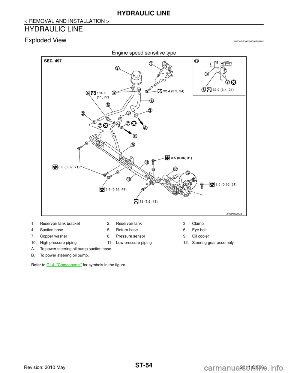
Exploded ViewINFOID:0000000006225615
Engine speed sensitive type
JPGIA0096GB
1. Reservoir tank bracket 2. Reservoir tank 3. Clamp
4. Suction hose 5. Return hose 6. Eye bolt
7. Copper washer 8. Pressure sensor 9. Oil cooler
10. High pressure piping 11. Low pressure piping 12. Steering gear assembly
A. To power steering oil pump suction hose.
B. To power steering oil pump.
Refer to GI-4, "
Components" for symbols in the figure.
Revision: 2010 May2011 QX56
Page 5042 of 5598

HYDRAULIC LINEST-55
< REMOVAL AND INSTALLATION >
C
DE
F
H I
J
K L
M A
B
ST
N
O P
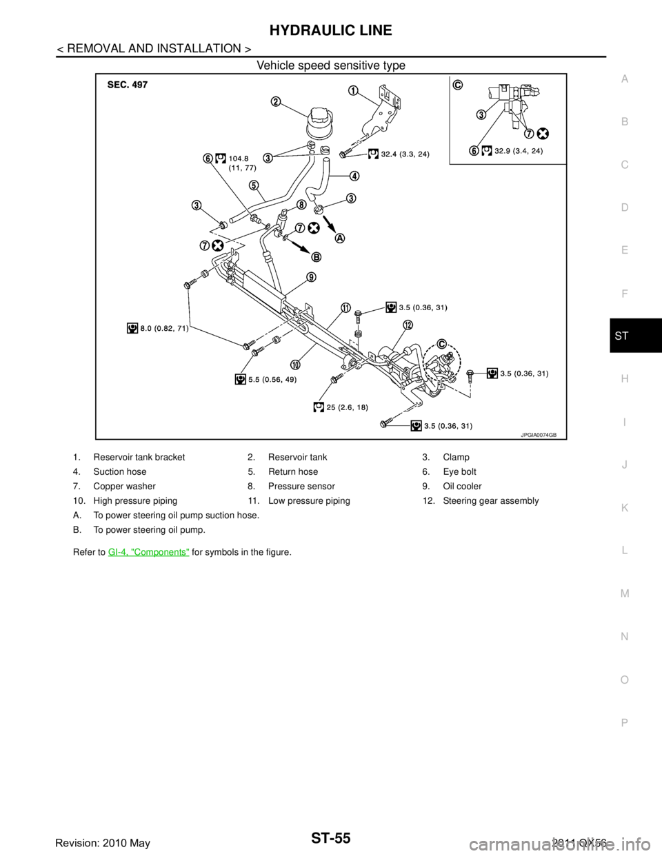
Vehicle speed sensitive type
JPGIA0074GB
1. Reservoir tank bracket 2. Reservoir tank 3. Clamp
4. Suction hose 5. Return hose 6. Eye bolt
7. Copper washer 8. Pressure sensor 9. Oil cooler
10. High pressure piping 11. Low pressure piping 12. Steering gear assembly
A. To power steering oil pump suction hose.
B. To power steering oil pump.
Refer to GI-4, "
Components" for symbols in the figure.
Revision: 2010 May2011 QX56
Page 5051 of 5598

STC-6
< SYSTEM DESCRIPTION >
SYSTEM
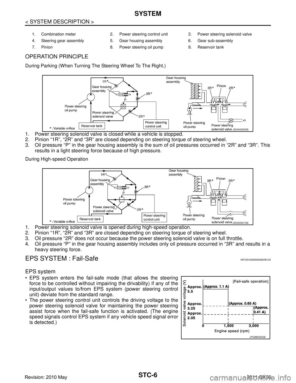
OPERATION PRINCIPLE
During Parking (When Turning The Steering Wheel To The Right.)
1. Power steering solenoid valve is closed while a vehicle is stopped.
2. Pinion “1R”, “2R” and “3R” are closed depending on steering torque of steering wheel.
3. Oil pressure “P” in the gear housing assembly is the sum of oil pressures occurred in “2R” and “3R”. Thisresults in a light steering force because of high pressure.
During High-speed Operation
1. Power steering solenoid valve is opened during high-speed operation.
2. Pinion “1R”, “2R” and “3R” are closed depending on steering torque of steering wheel.
3. Oil pressure “2R” does not occur because the pow er steering solenoid valve is on full throttle.
4. Oil pressure “P” in the gear housing assembly includes only oil pressure occurred in “3R” and results in a heavy steering force.
EPS SYSTEM : Fail-Safe INFOID:0000000006256120
EPS system
EPS system enters the fail-safe mode (that allows the steering
force to be controlled without impairi ng the drivability) if any of the
input/output values to/from EPS system (power steering control
unit) deviate from the standard range.
The power steering control unit controls the driving voltage to the
power steering solenoid valve for maintaining the power steering
assist force when the fail-safe function is activated. (The engine
speed signals control EPS system if any vehicle speed signal error
is detected.)
1. Combination meter 2. Power steering control unit 3. Power steering solenoid valve
4. Steering gear assembly 5. Gear housing assembly 6. Gear sub-assembly
7. Pinion 8. Power steering oil pump 9. Reservoir tank
JSGIA0020GB
JSGIA0021GB
JPGIB0022GB
Revision: 2010 May2011 QX56
Page 5058 of 5598

DIAGNOSIS AND REPAIR WORK FLOWSTC-13
< BASIC INSPECTION >
C
DE
F
H I
J
K L
M A
B
STC
N
O P
BASIC INSPECTION
DIAGNOSIS AND REPAIR WORK FLOW
Work FlowINFOID:0000000006256124
DETAILED FLOW
1.COLLECT THE INFORMATION FROM THE CUSTOMER
It is also important to clarify customer complaints before inspection. First of all, reproduce symptoms and
understand them fully. Ask customer about his/her complaints carefully. In some cases, it is necessary to
check symptoms by driving vehicle with customer.
CAUTION:
Customers are not professional. It is danger ous to make an easy guess like “maybe the customer
means that...,” or “maybe the cu stomer mentions this symptom”.
>> GO TO 2.
2.CHECK THE STATUS
1. Power steering fluid leakage and check the power steering fluid level. Refer to ST-30, "
Inspection".
2. Check the drive belt tension. Refer to EM-20, "
Checking".
3. Check the power steering gear for damages, cracks and fluid leakage. Refer to ST-46, "
Inspection".
4. Check the relief oil pressure. Refer to ST-52, "
Inspection".
>> GO TO 3.
3.DIAGNOSIS CHART BY SYMPTOM
Perform the diagnosis by symptom. Refer to STC-22, "
Diagnosis Procedure".
>> GO TO 4.
4.FINAL CHECK
Check the input/output standard values for the power steering control unit.
Are the power steering control unit input/output values within standard ranges respectively?
YES >> INSPECTION END
NO >> GO TO 2.
Revision: 2010 May2011 QX56
Page 5101 of 5598
![INFINITI QX56 2011 Factory Service Manual
COMPONENT PARTSTM-13
< SYSTEM DESCRIPTION > [7AT: RE7R01B]
C
EF
G H
I
J
K L
M A
B
TM
N
O P
A/T CONTROL SYSTEM : High and Lo w Reverse Clutch Solenoid ValveINFOID:0000000006226748
The high and low r INFINITI QX56 2011 Factory Service Manual
COMPONENT PARTSTM-13
< SYSTEM DESCRIPTION > [7AT: RE7R01B]
C
EF
G H
I
J
K L
M A
B
TM
N
O P
A/T CONTROL SYSTEM : High and Lo w Reverse Clutch Solenoid ValveINFOID:0000000006226748
The high and low r](/manual-img/42/57033/w960_57033-5100.png)
COMPONENT PARTSTM-13
< SYSTEM DESCRIPTION > [7AT: RE7R01B]
C
EF
G H
I
J
K L
M A
B
TM
N
O P
A/T CONTROL SYSTEM : High and Lo w Reverse Clutch Solenoid ValveINFOID:0000000006226748
The high and low reverse clutch solenoid valve is controlled by the TCM in response to signals transmitted
from the transmission range switch, output speed sens or and accelerator pedal position sensor. Gears will
then be shifted to the optimum position.
The high and low reverse clutch solenoid valve controls the high and low reverse clutch control valve in response to a signal transmitted from the TCM.
A/T CONTROL SYSTEM : Lo w Brake Solenoid ValveINFOID:0000000006226749
The low brake solenoid valve is controlled by the TC M in response to signals transmitted from the transmis-
sion range switch, output speed sensor and accelerator pedal position sensor. Gears will then be shifted to
the optimum position.
The low brake solenoid valve controls the low brake control valve in response to a signal transmitted from
the TCM.
A/T CONTROL SYSTEM : Anti-interlock Solenoid ValveINFOID:0000000006226750
Anti-interlock solenoid valve prevents the simultaneous activation of the input clutch and the low brake.
The anti-interlock solenoid valve is an ON/OFF type solenoid valve.
A/T CONTROL SYSTEM : 2 346 Brake Solenoid ValveINFOID:0000000006226751
The 2346 brake solenoid valve is controlled by the TC M in response to signals transmitted from the trans-
mission range switch, output speed sensor and accelera tor pedal position sensor. Gears will then be shifted
to the optimum position.
The 2346 brake solenoid valve controls the 2346 brake c ontrol valve in response to a signal transmitted from
the TCM.
A/T CONTROL SYSTEM : Torque Co nverter Clutch Solenoid ValveINFOID:0000000006226752
The torque converter clutch solenoid va lve is activated, with the gear in D2, D3, D4, D5, D6, D7, M2, M3, M4,
M5, M6 and M7 by the TCM in response to signals tr ansmitted from the output speed sensor and accelerator
pedal position sensor. Torque converter clut ch piston operation will then be controlled.
A/T CONTROL SYSTEM : Line Pressure Solenoid ValveINFOID:0000000006226753
The line pressure solenoid valve regulates the oil pum p discharge pressure to suit the driving condition in
response to a signal transmitted from the TCM.
A/T CONTROL SYSTEM : Accele rator Pedal Position SensorINFOID:0000000006226754
The accelerator pedal position sensor is installed on the upper end of the accelerator pedal assembly.
The accelerator pedal position sensor detects the accelerator position.
The accelerator pedal position sensor transform the a ccelerator pedal position into output voltage, and emit
the voltage signal to the ECM. Then, the TCM receives accelerator pedal position signal from the ECM via
CAN communication.
A/T CONTROL SYSTEM : Manual Mode SwitchINFOID:0000000006226755
The manual mode switch [mode select switch and position se lect switch (shift-up/shift-down)] is installed in
the A/T shift selector assembly.
The mode select switch detects the position (the main shift gate side or manual shift gate side) of the selec-
tor lever and transmits a manual mode signal or a not manual mode signal to the combination meter. Then,
the TCM receives a manual mode signal or non-manual mode signal from the combination meter.
The position select switch (shift-up) detects that the se lector lever is shifted to the shift-up side of the manual
shift gate and transmits a manual mode shift up signal to the combination meter. Then, the TCM receives a
manual mode shift up signal from the combination meter.
The position select switch (shift-down) detects that the selector lever is shifted to the shift-down side of the
manual shift gate and transmits a manual mode shift down signal to the combination meter. Then, the TCM
receives a manual mode shift down signal from the combination meter.
Revision: 2010 May2011 QX56
Page 5141 of 5598
![INFINITI QX56 2011 Factory Service Manual
SYSTEMTM-53
< SYSTEM DESCRIPTION > [7AT: RE7R01B]
C
EF
G H
I
J
K L
M A
B
TM
N
O P
Input/Output Signal Chart
*: This signal is transmitted via communication line.
The TCM activates low brake solenoid INFINITI QX56 2011 Factory Service Manual
SYSTEMTM-53
< SYSTEM DESCRIPTION > [7AT: RE7R01B]
C
EF
G H
I
J
K L
M A
B
TM
N
O P
Input/Output Signal Chart
*: This signal is transmitted via communication line.
The TCM activates low brake solenoid](/manual-img/42/57033/w960_57033-5140.png)
SYSTEMTM-53
< SYSTEM DESCRIPTION > [7AT: RE7R01B]
C
EF
G H
I
J
K L
M A
B
TM
N
O P
Input/Output Signal Chart
*: This signal is transmitted via communication line.
The TCM activates low brake solenoid valve and controls t he low brake oil pressure to the low pressure level
if the driver does not intend to start the vehicle while the vehicle is being stopped in the “D” position. Therefore,
the low brake is in the release (slip) status and the pow er transmission route of A/T is the same status as the
“N” position. This can decrease the engine load and im proves the fuel economy because the drive force of
engine is not transmitted to the output shaft of A/T.
Idle Neutral Contro l Start Condition
Idle neutral control starts when all of the following c onditions are satisfied. However, the control ends when
any one of the following conditions becomes insufficient during idle neutral control.
NOTE:
The idle neutral control is terminated or prohibited when the TCM and ECM detect that the vehicle is in any of
the conditions as per the following.
Engine cooling water temperature and A/T fluid temperature are below or above a prescribed temperature.
A/T malfunction occurs.
DTC is detected.
Fail-safe mode activates.
Idle neutral control is performed continuously for a certain period of time.
Idle Neutral Contro l Resume Condition
Idle neutral control can be resumed when its start condition is fulfilled after any of the following operations is
performed (unless a malfunction occurs in the vehicle).
After driving at more than a prescribed speed.
When idle neutral control start conditions are fulfilled for a certain period of time.
SHIFT PATTERN CONTROL
Item Signal
TCM function Actuator
Each sensor, switch and
control unit ⇒ TCM TCM
⇒ ECM ECM ⇒ TCM
Input speed sensor 1, 2 Input speed
N idle instruction
signal (Standby sig- nal)* N idle instruction
signal (Start signal)* Idle neutral con-
trol Low brake sole-
noid valve
Output speed sensor Output shaft revolution
A/T fluid temperature
sensor
ATF temperature
Transmission range
switch Selector lever position
ECM Engine speed signal*
Accelerator pedal posi-
tion signal*
Throttle position signal*
BCM Stop lamp switch signal*
Turn indicator signal*
ABS actuator electric
unit (control unit) Pressure sensor signal*
Decel G sensor signal*
Combination meter Vehicle speed signal*
Driving location : Level road and gentle slope
Selector lever position : “D” position
Vehicle speed : 0 km/h (0 MPH)
Accelerator pedal opening : 0.0 / 8
Brake pedal : Depress
Engine speed : Idle speed
Snow mode switch : OFF
Turn signal lamp and ha zard warning lamp : OFF
Revision: 2010 May2011 QX56
Page 5150 of 5598
![INFINITI QX56 2011 Factory Service Manual
TM-62
< SYSTEM DESCRIPTION >[7AT: RE7R01B]
DIAGNOSIS SYSTEM (TCM)
INPUT SPEED (rpm) X X Displays the input speed calculated from front
sun gear revolution and front carrier revolution.
F SUN GR REV INFINITI QX56 2011 Factory Service Manual
TM-62
< SYSTEM DESCRIPTION >[7AT: RE7R01B]
DIAGNOSIS SYSTEM (TCM)
INPUT SPEED (rpm) X X Displays the input speed calculated from front
sun gear revolution and front carrier revolution.
F SUN GR REV](/manual-img/42/57033/w960_57033-5149.png)
TM-62
< SYSTEM DESCRIPTION >[7AT: RE7R01B]
DIAGNOSIS SYSTEM (TCM)
INPUT SPEED (rpm) X X Displays the input speed calculated from front
sun gear revolution and front carrier revolution.
F SUN GR REV (rpm) — — Displays the front sun gear revolution calculat-
ed from the pulse signal of input speed sensor
1.
F CARR GR REV (rpm) — — Displays the front carrier gear revolution calcu-
lated from the pulse signal of input speed sen-
sor 2.
ENGINE SPEED (rpm) X X Displays the engine speed received via CAN
communication.
TC SLIP SPEED (rpm) — X Displays the revolution difference between in-
put speed and engine speed.
ACCELE POSI (0.0/8) X — Displays the accelerator position estimated val-
ue received via CAN communication.
THROTTLE POSI (0.0/8) X X Displays the throttle position received via CAN
communication.
ATF TEMP 1 ( °C or °F) X X Displays the ATF temperature of oil pan calcu-
lated from the signal voltage of A/T fluid tem-
perature sensor.
ATF TEMP 2 ( °C or °F) X X Displays the ATF temperature estimated value
of torque converter outlet calculated from the
signal voltage of A/T fluid temperature sensor.
ATF TEMP SE 1 (V) — — Displays the signal voltage of A/T fluid temper-
ature sensor.
BATTERY VOLT (V) X — Displays the power supply voltage of TCM.
LINE PRES SOL (A) — X Displays the command current from TCM to the
line pressure solenoid.
TCC SOLENOID (A) — X Displays the command current from TCM to the
torque converter clutch solenoid.
L/B SOLENOID (A) — X Displays the command current from TCM to the
low brake solenoid.
FR/B SOLENOID (A) — X Displays the command current from TCM to the
front brake solenoid.
HLR/C SOL (A) — X Displays the command current from TCM to the
high and low reverse clutch solenoid.
I/C SOLENOID (A) — X Displays the command current from TCM to the
input clutch solenoid.
D/C SOLENOID (A) — X Displays the command current from TCM to the
direct clutch solenoid.
2346/B SOL (A) — X Displays the command current from TCM to the
2346 brake solenoid.
L/P SOL MON (A) — — Monitors the command current from TCM to the
line pressure solenoid, and displays the moni-
tor value.
TCC SOL MON (A) — — Monitors the command current from TCM to the
torque converter clutch solenoid, and displays
the monitor value.
L/B SOL MON (A) — — Monitors the command current from TCM to the
low brake solenoid, and displays the monitor
value.
Monitored item (Unit)
Monitor Item Selection
Remarks
ECU IN-
PUT SIG- NALS MAIN SIG-
NALS SELEC-
TION
FROM ITEM
Revision: 2010 May2011 QX56
Page 5151 of 5598
![INFINITI QX56 2011 Factory Service Manual
DIAGNOSIS SYSTEM (TCM)TM-63
< SYSTEM DESCRIPTION > [7AT: RE7R01B]
C
EF
G H
I
J
K L
M A
B
TM
N
O P
FR/B SOL MON (A) — — Monitors the command current from TCM to the
front brake solenoid, and disp INFINITI QX56 2011 Factory Service Manual
DIAGNOSIS SYSTEM (TCM)TM-63
< SYSTEM DESCRIPTION > [7AT: RE7R01B]
C
EF
G H
I
J
K L
M A
B
TM
N
O P
FR/B SOL MON (A) — — Monitors the command current from TCM to the
front brake solenoid, and disp](/manual-img/42/57033/w960_57033-5150.png)
DIAGNOSIS SYSTEM (TCM)TM-63
< SYSTEM DESCRIPTION > [7AT: RE7R01B]
C
EF
G H
I
J
K L
M A
B
TM
N
O P
FR/B SOL MON (A) — — Monitors the command current from TCM to the
front brake solenoid, and displays the monitor
value.
HLR/C SOL MON (A) — — Monitors the command current from TCM to the
high and low reverse clutch solenoid, and dis-
plays the monitor value.
I/C SOL MON (A) — — Monitors the command current from TCM to the
input clutch solenoid, and displays the monitor
value.
D/C SOL MON (A) — — Monitors the command current from TCM to the
direct clutch solenoid, and displays the monitor
value.
2346/B SOL MON (A) — — Monitors the command current from TCM to the
2346 brake solenoid, and displays the monitor
value.
GEAR RATIO — X Displays the gear ratio calculated from input
speed and output speed.
ENGINE TORQUE (Nm) — — Displays the engine torque estimated value re-
ceived via CAN communication.
ENG TORQUE D (Nm) — — Displays the engine torque estimated value re-
flected the requested torque of each control unit
received via CAN communication.
INPUT TRQ S (Nm) — — Displays the input torque using for the oil pres-
sure calculation process of shift change control.
INPUT TRQ L/P (Nm) — — Displays the input torque using for the oil pres-
sure calculation process of line pressure con-
trol.
TRGT PRES L/P (kPa, kg/cm
2 or psi)—— Displays the target oil pressure value of torque
converter clutch solenoid valve calculated by
the oil pressure calculation process of lock-up
control.
TRGT PRES TCC (kPa, kg/cm
2 or psi)—— Displays the target oil pressure value of torque
converter clutch solenoid valve calculated by
the oil pressure calculation process of shift
change control.
TRGT PRES L/B (kPa, kg/cm
2 or psi)—— Displays the target oil pressure value of low
brake solenoid valve calculated by the oil pres-
sure calculation process of shift change control.
TRGT PRE FR/B (kPa, kg/cm
2 or psi)—— Displays the target oil pressure value of front
brake solenoid valve calculated by the oil pres-
sure calculation process of shift change control.
TRG PRE HLR/C (kPa, kg/cm
2 or psi)—— Displays the target oil pressure value of high
and low reverse clutch solenoid valve calculat-
ed by the oil pressure calculation process of
shift change control.
TRGT PRES I/C (kPa, kg/cm
2 or psi)—— Displays the target oil pressure value of input
clutch solenoid valve calculated by the oil pres-
sure calculation process of shift change control.
TRGT PRES D/C (kPa, kg/cm
2 or psi)—— Displays the target oil pressure value of direct
clutch solenoid valve calculated by the oil pres-
sure calculation process of shift change control.
Monitored item (Unit)
Monitor Item Selection
Remarks
ECU IN-
PUT SIG- NALS MAIN SIG-
NALS SELEC-
TION
FROM ITEM
Revision: 2010 May2011 QX56