2011 INFINITI QX56 oil pressure
[x] Cancel search: oil pressurePage 3779 of 5598

MWI-36
< ECU DIAGNOSIS INFORMATION >
COMBINATION METER
LIGHT INDIgnition switch
ONTail lamp indicator lamp ON On
Tail lamp indicator lamp OFF Off
OIL W/L Ignition switch
ONOil pressure warning lamp ON On
Oil pressure warning lamp OFF Off
MIL Ignition switch
ONMalfunction indicator lamp ON On
Malfunction indicator lamp OFF Off
GLOW IND Ignition switch
ONNOTE:
This item is displayed, but cannot be moni-
tored.
Off
CRUISE IND Ignition switch
ONCRUISE indicator ON On
CRUISE indicator OFF Off
SET IND Ignition switch
ONSET indicator ON On
SET indicator OFF Off
CRUISE W/L Ignition switch
ONCRUISE warning lamp ON On
CRUISE warning lamp OFF Off
BA W/L Ignition switch
ONIBA OFF indicator lamp ON On
IBA OFF indicator lamp OFF Off
ATC/T-AMT W/L Ignition switch
ONA/T check warning lamp ON On
A/T check warning lamp OFF Off
ATF TEMP W/L Ignition switch
ONNOTE:
This item is displayed, but cannot be moni-
tored.
Off
4WD W/L Ignition switch
ON4WD warning lamp ON On
4WD warning lamp OFF Off
FUEL W/L Ignition switch
ONDuring low fuel warning indication On
Other than the above Off
WASHER W/L Ignition switch
ONDuring low washer flui
d warning indication On
Other than the above Off
AIR PRES W/L Ignition switch
ONLow tire pressure
warning lamp ON On
Low tire pressure warning lamp OFF Off
KEY G/Y W/L Ignition switch
ONKEY warning lamp (Green/Yellow) ON On
KEY warning lamp (Green/Yellow) OFF Off
KEY KNOB W/L Ignition switch
ONNOTE:
This item is displayed, but cannot be moni-
tored.
Off
AFS OFF IND Ignition switch
ONAFS OFF indicator lamp ON On
AFS OFF indicator lamp OFF Off
DDS W/L Ignition switch
ONNOTE:
This item is displayed, but cannot be moni-
tored.
Off
LANE W/L
Ignition switch
ONLane departure warning lamp ON On
Lane departure warning lamp OFF Off
LDP IND Ignition switch
ONLDP ON indicator lamp ON On
LDP ON indicator lamp OFF Off
AT P W / L Ignition switch
ONATP warning lamp ON On
ATP warning lamp OFF Off
Monitor Item Condition Value/Status
Revision: 2010 May2011 QX56
Page 3785 of 5598

MWI-42
< ECU DIAGNOSIS INFORMATION >
COMBINATION METER
Fail-Safe
INFOID:0000000006221722
FA I L - S A F E
The combination meter activates the fail-safe contro l if CAN communication with each unit is malfunctioning.
37
(R/Y) Ground Non-manual mode signal Input Ignition
switch
ONSelector manual mode po-
sition
12 V
Other than the above 0 V
38
(L/W) Ground Manual mode shift down
signal InputIgnition
switch
ON Selector lever DOWN oper-
ation
0 V
Other than the above 12 V
39
(Y/B) Ground Manual mode shift up sig-
nal InputIgnition
switch
ON Selector lever UP operation 0 V
Other than the above 12 V
40
(G/W) Ground Manual mode signal Input Ignition
switch
ONSelector manual mode po-
sition
0 V
Other than the above 12 V
Te r m i n a l N o .
(Wire color) Description
ConditionVa l u e
(Approx.)
+ – Signal name Input/
Output
Function Specifications
Speedometer
Reset to zero by suspending communication.
Tachometer
Engine coolant temperature gauge
Engine oil pressure gauge
Illumination control When suspending communication, changes to nighttime mode.
Information display Odo/trip meter An indicated value is maintained at communications blackout.
Shift position indicator The display turns OFF by suspending communication.
Door open warning The display turns OFF by suspending communication.
Buzzer The buzzer turns OFF by suspending communication.
Revision: 2010 May2011 QX56
Page 3786 of 5598

MWI
COMBINATION METERMWI-43
< ECU DIAGNOSIS INFORMATION >
C
DE
F
G H
I
J
K L
M B A
O P
DTC IndexINFOID:0000000006221723
Warning lamp/indicator lamp ABS warning lamp
The lamp turns ON by suspending communication.
VDC warning lamp
Brake warning lamp
IBA OFF indicator lamp
4WD warning lamp
Malfunction indicator lamp
VDC OFF indicator lamp
CRUISE warning lamp
Low tire pressure warning lamp The lamp blinking caused by suspending communication.
High beam indicator lamp
The lamp turns OFF by suspending communication.
Turn signal indicator lamp
Tail lamp indicator lamp
A/T CHECK indicator lamp
Key warning lamp
AT P w a r n i n g l a m p
Lane departure warning lamp
LDP ON indicator lamp
CRUISE indicator lamp
Oil pressure warning lamp
SNOW mode indicator lamp
TOW mode indicator lamp
CK SUSP indicator lamp
BSW indicator lamp
Function Specifications
Display contents of CONSULT-III Diagnostic item is detected when... Refer to
CAN COMM CIRCUIT
[U1000] When combination meter is not transmitting or receiving CAN communication signal
for 2 seconds or more. MWI-59,
"Diagnosis
Procedure"
CONTROL UNIT (CAN)
[U1010]
When detecting error during the initial diagnosis of the CAN controller of combina-
tion meter. MWI-60, "Diagnosis
Procedure"
VEHICLE SPEED
[B2205]
The abnormal vehicle speed signal is input from the ABS actuator and electric unit
(control unit) for
2 seconds or more. MWI-61, "Diagnosis
Procedure"
ENGINE SPEED
[B2267]
If ECM continuously transmits abnormal engine speed signals for 2 seconds or
more. MWI-62, "Diagnosis
Procedure"
WATER TEMP
[B2268]
If ECM continuously transmits abnormal engine coolant temperature signals for 60
seconds or more. MWI-63, "Diagnosis
Procedure"
Revision: 2010 May2011 QX56
Page 3814 of 5598

MWI
OIL PRESSURE SWITCH SIGNAL CIRCUIT
MWI-71
< DTC/CIRCUIT DIAGNOSIS >
C
D E
F
G H
I
J
K L
M B A
O P
OIL PRESSURE SWITCH SIGNAL CIRCUIT
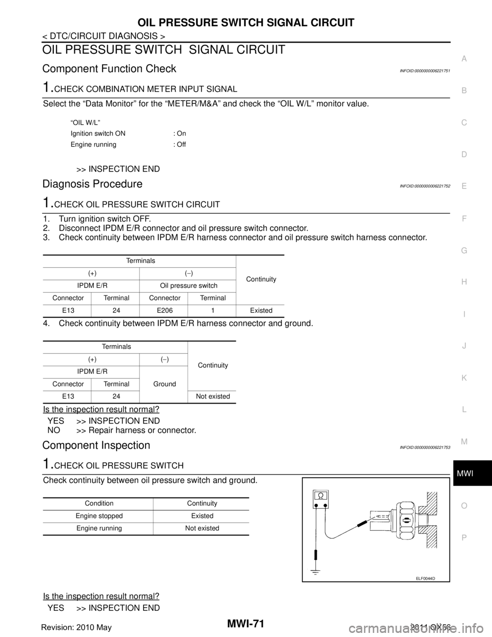
Component Function CheckINFOID:0000000006221751
1.CHECK COMBINATION METER INPUT SIGNAL
Select the “Data Monitor” for the “METER/M& A” and check the “OIL W/L” monitor value.
>> INSPECTION END
Diagnosis ProcedureINFOID:0000000006221752
1.CHECK OIL PRESSURE SWITCH CIRCUIT
1. Turn ignition switch OFF.
2. Disconnect IPDM E/R connector and oil pressure switch connector.
3. Check continuity between IPDM E/R harness c onnector and oil pressure switch harness connector.
4. Check continuity between IPDM E/R harness connector and ground.
Is the inspection result normal?
YES >> INSPECTION END
NO >> Repair harness or connector.
Component InspectionINFOID:0000000006221753
1.CHECK OIL PRESSURE SWITCH
Check continuity between oil pressure switch and ground.
Is the inspection result normal?
YES >> INSPECTION END
“OIL W/L”
Ignition switch ON : On
Engine running : Off
Te r m i n a l s Continuity
(+) (
−)
IPDM E/R Oil pressure switch
Connector Terminal Connector Terminal E1324E2061Existed
Te r m i n a l s Continuity
(+) (
−)
IPDM E/R Ground
Connector Terminal
E13 24 Not existed
Condition Continuity
Engine stopped Existed Engine running Not existed
ELF0044D
Revision: 2010 May2011 QX56
Page 3815 of 5598

MWI-72
< DTC/CIRCUIT DIAGNOSIS >
OIL PRESSURE SWITCH SIGNAL CIRCUIT
NO >> Replace oil pressure switch. Refer to EM-58, "Removal and Installation".
Revision: 2010 May2011 QX56
Page 3821 of 5598

MWI-78
< SYMPTOM DIAGNOSIS >
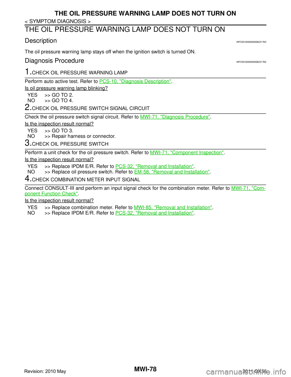
THE OIL PRESSURE WARNING LAMP DOES NOT TURN ON
THE OIL PRESSURE WARNING LAMP DOES NOT TURN ON
DescriptionINFOID:0000000006221763
The oil pressure warning lamp stays off when the ignition switch is turned ON.
Diagnosis ProcedureINFOID:0000000006221764
1.CHECK OIL PRESSURE WARNING LAMP
Perform auto active test. Refer to PCS-10, "
Diagnosis Description".
Is oil pressure warning lamp blinking?
YES >> GO TO 2.
NO >> GO TO 4.
2.CHECK OIL PRESSURE SWITCH SIGNAL CIRCUIT
Check the oil pressure switch signal circuit. Refer to MWI-71, "
Diagnosis Procedure".
Is the inspection result normal?
YES >> GO TO 3.
NO >> Repair harness or connector.
3.CHECK OIL PRESSURE SWITCH
Perform a unit check for the oil pressure switch. Refer to MWI-71, "
Component Inspection".
Is the inspection result normal?
YES >> Replace IPDM E/R. Refer to PCS-32, "Removal and Installation".
NO >> Replace oil pressure switch. Refer to EM-58, "
Removal and Installation".
4.CHECK COMBINATION METER INPUT SIGNAL
Connect CONSULT-III and perform an input signal check for the combination meter. Refer to MWI-71, "
Com-
ponent Function Check".
Is the inspection result normal?
YES >> Replace combination meter. Refer to MWI-85, "Removal and Installation".
NO >> Replace IPDM E/R. Refer to PCS-32, "
Removal and Installation".
Revision: 2010 May2011 QX56
Page 3822 of 5598

MWI
THE OIL PRESSURE WARNING LAMP DOES NOT TURN OFFMWI-79
< SYMPTOM DIAGNOSIS >
C
DE
F
G H
I
J
K L
M B A
O P
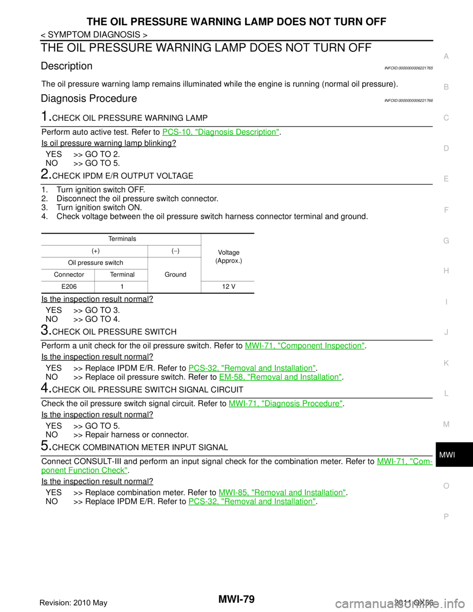
THE OIL PRESSURE WARNING LAMP DOES NOT TURN OFF
DescriptionINFOID:0000000006221765
The oil pressure warning lamp remains illuminated while the engine is running (normal oil pressure).
Diagnosis ProcedureINFOID:0000000006221766
1.CHECK OIL PRESSURE WARNING LAMP
Perform auto active test. Refer to PCS-10, "
Diagnosis Description".
Is oil pressure warning lamp blinking?
YES >> GO TO 2.
NO >> GO TO 5.
2.CHECK IPDM E/R OUTPUT VOLTAGE
1. Turn ignition switch OFF.
2. Disconnect the oil pressure switch connector.
3. Turn ignition switch ON.
4. Check voltage between the oil pressure switch harness connector terminal and ground.
Is the inspection result normal?
YES >> GO TO 3.
NO >> GO TO 4.
3.CHECK OIL PRESSURE SWITCH
Perform a unit check for the oil pressure switch. Refer to MWI-71, "
Component Inspection".
Is the inspection result normal?
YES >> Replace IPDM E/R. Refer to PCS-32, "Removal and Installation".
NO >> Replace oil pressure switch. Refer to EM-58, "
Removal and Installation".
4.CHECK OIL PRESSURE SWITCH SIGNAL CIRCUIT
Check the oil pressure switch signal circuit. Refer to MWI-71, "
Diagnosis Procedure".
Is the inspection result normal?
YES >> GO TO 5.
NO >> Repair harness or connector.
5.CHECK COMBINATION METER INPUT SIGNAL
Connect CONSULT-III and perform an input signal check for the combination meter. Refer to MWI-71, "
Com-
ponent Function Check".
Is the inspection result normal?
YES >> Replace combination meter. Refer to MWI-85, "Removal and Installation".
NO >> Replace IPDM E/R. Refer to PCS-32, "
Removal and Installation".
Te r m i n a l s
Voltag e
(Approx.)
(+) (
−)
Oil pressure switch Ground
Connector Terminal
E206 1 12 V
Revision: 2010 May2011 QX56
Page 3849 of 5598
![INFINITI QX56 2011 Factory Service Manual
PCS-8
< SYSTEM DESCRIPTION >[IPDM E/R]
SYSTEM
POWER CONTROL SYSTEM : System Diagram
INFOID:0000000006220164
POWER CONTROL SYSTEM : System DescriptionINFOID:0000000006220165
COOLING FAN CONTROL
IPDM INFINITI QX56 2011 Factory Service Manual
PCS-8
< SYSTEM DESCRIPTION >[IPDM E/R]
SYSTEM
POWER CONTROL SYSTEM : System Diagram
INFOID:0000000006220164
POWER CONTROL SYSTEM : System DescriptionINFOID:0000000006220165
COOLING FAN CONTROL
IPDM](/manual-img/42/57033/w960_57033-3848.png)
PCS-8
< SYSTEM DESCRIPTION >[IPDM E/R]
SYSTEM
POWER CONTROL SYSTEM : System Diagram
INFOID:0000000006220164
POWER CONTROL SYSTEM : System DescriptionINFOID:0000000006220165
COOLING FAN CONTROL
IPDM E/R outputs cooling fan control signal (PWM signal ) to the electrically-controlled cooling fan coupling
according to the status of the cooling fan speed request signal received from ECM via CAN communication.
Refer to EC-41, "
COOLING FAN CONTROL : System Diagram".
ALTERNATOR CONTROL
IPDM E/R outputs power generation command signal (PWM signal ) to the alternator according to the status of
the power generation command value signal received from ECM via CAN communication. Refer to CHG-7,
"POWER GENERATION VOLTAGE VARIABLE CONTROL SYSTEM : System Diagram".
SIGNAL BUFFER SYSTEM
SIGNAL BUFFER SYSTEM : System DiagramINFOID:0000000006220166
SIGNAL BUFFER SYSTEM : System DescriptionINFOID:0000000006220167
IPDM E/R reads the status of the oil pressure switch and transmits the oil pressure switch signal to BCM via
CAN communication. Refer to MWI-15, "
OIL PRESSURE WARNING LAMP : System Diagram".
IPDM E/R reads the status of the hood switch and tr ansmits the hood switch signal to BCM via CAN commu-
nication. Refer to SEC-17, "
VEHICLE SECURITY SYSTEM : System Diagram".
IPDM E/R receives the rear window defogger control signal from BCM via CAN communication and trans- mits it to ECM and AV control unit via CAN communication. Refer to DEF-6, "
System Diagram".
POWER CONSUMPTION CONTROL SYSTEM
JMMIA0491GB
JPMIA0952GB
Revision: 2010 May2011 QX56