Page 684 of 5598
BODY COMPONENT PARTSBRM-9
< PREPARATION >
C
DE
F
G H
I
J
L
M A
B
BRM
N
O P
BODY COMPONENT PARTS
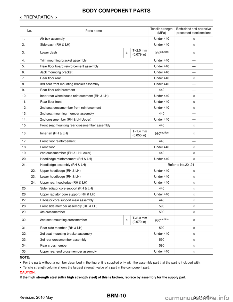
Underbody Component PartsINFOID:0000000006248487
: Both sided anti-corrosive precoated steel sections
: High strength steel (HSS) sections
: Both sided anti-corrosive steel and HSS sections
JSKIA1950ZZ
Revision: 2010 May2011 QX56
Page 685 of 5598

BRM-10
< PREPARATION >
BODY COMPONENT PARTS
NOTE:
For the parts without a number described in the figure, it is supplied only with the assembly part that the part is included with.
Tensile strength column shows the largest strength value of a part in the component part.
CAUTION:
If the high strength steel (ultra high strength steel) of this is broken, replace by assembly for the supply part. No. Parts name
Tensile strength
(MPa) Both sided anti-corrosive
precoated steel sections
1. Air box assembly Under 440 ×
2. Side dash (RH & LH) Under 440 ×
3. Lower dash a. T=2.0 mm
(0.079 in)
980
caution×
4. Trim mounting bracket assembly Under 440 —
5. Rear floor board reinforcement assembly Under 440 —
6. Jack mounting bracket Under 440 —
7. Rear floor rear Under 440 ×
8. 3rd seat front mounting bracket assembly Under 440 —
9. Rear floor reinforcement 440 —
10. Inner rear wheelhouse reinforcement (RH & LH) Under 440 ×
11. Rear floor front Under 440 ×
12. 2nd seat crossmember front reinforcement Under 440 ×
13. 2nd seat mounting member assembly 440 —
14. 2nd crossmember (RH & LH Upper) Under 440 —
15. Front seat mounting rear crossmember assembly 440 ×
16. Inner sill (RH & LH) T=1.4 mm
(0.055 in)
980
caution×
17. Front floor reinforcement 440 —
18. Front floor Under 440 ×
19. 2nd crossmember (RH & LH Lower) 440 ×
20. Hoodledge reinforcement (RH & LH) Under 440 ×
21. Hoodledge assembly (RH & LH) Refer to No.22 −24
22. Upper hoodledge (RH & LH) Under 440 ×
23. Lower hoodledge (RH & LH) Under 440 ×
24. Upper rear hoodledge (RH & LH) Under 440 ×
25. Side radiator core support (RH & LH) 440 ×
26. Upper radiator core support (RH & LH) Under 440 ×
27. Radiator core support main assembly 440 ×
28. Front side member assembly (RH & LH) 590 ×
29. 4th crossmember 590 ×
30. 2nd seat mounting crossmember b. T=2.0 mm
(0.079 in)
980
caution×
31. Rear side member (RH & LH) 590 ×
32. 3rd seat mounting bracket assembly Under 440 ×
33. 3rd rear crossmember assembly 590 ×
34. Rear crossmember 590 ×
35. Upper rear end crossmember assembly Under 440 ×
Revision: 2010 May2011 QX56
Page 686 of 5598
BODY COMPONENT PARTSBRM-11
< PREPARATION >
C
DE
F
G H
I
J
L
M A
B
BRM
N
O P
Body Component PartsINFOID:0000000006248488
: Both sided anti-corrosive precoated steel sections
: High strength steel (HSS) sections
: Both sided anti-corrosive steel and HSS sections
JSKIA1951ZZ
Revision: 2010 May2011 QX56
Page 687 of 5598

BRM-12
< PREPARATION >
BODY COMPONENT PARTS
NOTE:
For the parts without a number described in the figure, it is supplied only with the assembly part that the part is included with.
Tensile strength column shows the largest strength value of a part in the component part. No. Parts name
Tensile strength
(MPa) Both sided anti-corrosive
precoated steel sections
1. Hood Under 440×
2. Front fender (RH & LH) Under 440 ×
3. Inner side roof rail (RH & LH) 590 —
4. Upper inner front pillar (RH & LH) c. T=1.6 mm
(0.063 in)
980
caution—
5. Inner center pillar (RH & LH) d. T=1.6 mm
(0.063 in)
980
caution×
6. Center sill reinforcement assembly (RH & LH) Under 440 ×
7. Side body assembly (RH & LH) Refer to No.8 −13
8. Upper front pillar reinforcement (RH & LH) 590 —
9. Lower center pillar brace (RH & LH) e. T=1.8 mm
(0.071 in)
980
caution—
10. Front pillar brace (RH & LH) 590 —
11. Outer sill reinforcement (RH & LH) 590 ×
12. Outer front side body (RH & LH) Under 440 ×
13. Front fender bracket assembly (RH & LH) Under 440 ×
14. Outer sill (RH & LH) Under 440 ×
15. Front door assembly (RH & LH) 440 ×
16. Outer front door panel (RH & LH) Under 440 ×
17. Rear door assembly (RH & LH) 440 ×
18. Outer rear door panel (RH & LH) Under 440 ×
19. Back pillar reinforcement (RH & LH) Under 440 —
20. Inner back pillar (RH & LH) Under 440 —
21. Inner rear side roof rail (RH & LH) Under 440 —
22. Inner rear pillar (RH & LH) 590 —
23. Lower inner rear pillar (RH & LH)v Under 440 —
24. Side panel reinforcement (RH & LH) Under 440 —
25. Outer rear wheelhouse (RH & LH) Under 440 ×
26. Inner rear wheelhouse (RH & LH) Under 440 ×
27. Outer rear wheelhouse extension (RH & LH) Under 440 ×
28. Roof assembly Under 440 —
29. Front roof rail 440 —
30. Roof bow No.3 Under 440 —
31. Roof bow No.4 Under 440 —
32. Roof bow No.5 Under 440 —
33. Rear roof rail 440 —
34. Rear fender (RH & LH) Under 440 ×
35. Back pillar assembly (RH & LH) Under 440 —
36. Rear fender bracket (RH & LH) Under 440 —
37. Fuel filler lid Under 440 ×
38. Rear fender extension (RH & LH) Under 440 ×
39. Back door Under 440 ×
Revision: 2010 May2011 QX56
Page 689 of 5598

BRM-14
< PREPARATION >
BODY COMPONENT PARTS
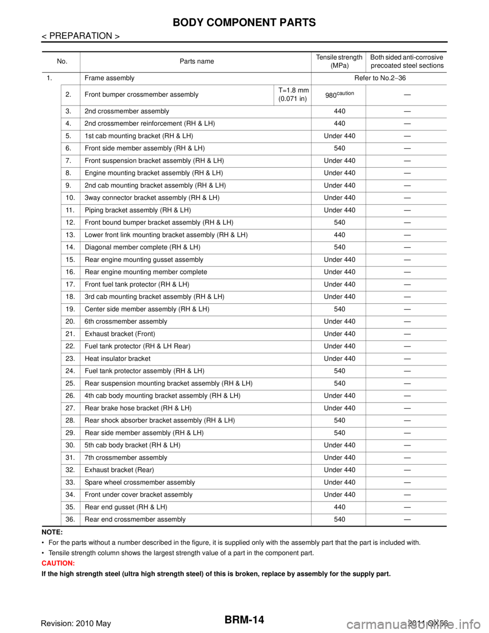
NOTE:
For the parts without a number described in the figure, it is supplied only with the assembly part that the part is included with.
Tensile strength column shows the largest strength value of a part in the component part.
CAUTION:
If the high strength steel (ultra high strength steel) of this is broken, replace by assembly for the supply part. No. Parts name
Tensile strength
(MPa) Both sided anti-corrosive
precoated steel sections
1. Frame assembly Refer to No.2−36
2. Front bumper crossmember assembly T=1.8 mm
(0.071 in)
980
caution—
3. 2nd crossmember assembly 440 —
4. 2nd crossmember reinforcement (RH & LH) 440 —
5. 1st cab mounting bracket (RH & LH) Under 440 —
6. Front side member assembly (RH & LH) 540 —
7. Front suspension bracket assembly (RH & LH) Under 440 —
8. Engine mounting bracket assembly (RH & LH) Under 440 —
9. 2nd cab mounting bracket assembly (RH & LH) Under 440 —
10. 3way connector bracket assembly (RH & LH) Under 440 —
11. Piping bracket assembly (RH & LH) Under 440 —
12. Front bound bumper bracket assembly (RH & LH) 540 —
13. Lower front link mounting bracket assembly (RH & LH) 440 —
14. Diagonal member complete (RH & LH) 540 —
15. Rear engine mounting gusset assembly Under 440 —
16. Rear engine mounting member complete Under 440 —
17. Front fuel tank protector (RH & LH) Under 440 —
18. 3rd cab mounting bracket assembly (RH & LH) Under 440 —
19. Center side member assembly (RH & LH) 540 —
20. 6th crossmember assembly Under 440 —
21. Exhaust bracket (Front) Under 440 —
22. Fuel tank protector (RH & LH Rear) Under 440 —
23. Heat insulator bracket Under 440 —
24. Fuel tank protector assembly (RH & LH) 540 —
25. Rear suspension mounting bracket assembly (RH & LH) 540 —
26. 4th cab body mounting bracket assembly (RH & LH) Under 440 —
27. Rear brake hose bracket (RH & LH) Under 440 —
28. Rear shock absorber bracket assembly (RH & LH) 540 —
29. Rear side member assembly (RH & LH) 540 —
30. 5th cab body bracket (RH & LH) Under 440 —
31. 7th crossmember assembly Under 440 —
32. Exhaust bracket (Rear) Under 440 —
33. Spare wheel crossmember assembly Under 440 —
34. Front under cover bracket assembly Under 440 —
35. Rear end gusset (RH & LH) 440 —
36. Rear end crossmember assembly 540 —
Revision: 2010 May2011 QX56
Page 690 of 5598

CORROSION PROTECTIONBRM-15
< REMOVAL AND INSTALLATION >
C
DE
F
G H
I
J
L
M A
B
BRM
N
O P
REMOVAL AND INSTALLATION
CORROSION PROTECTION
DescriptionINFOID:0000000006248490
To provide improved corrosion prevention, the follo wing anti-corrosive measures have been implemented in
NISSAN production plants. When repairing or replacing body panels, it is necessary to use the same anti-cor-
rosive measures.
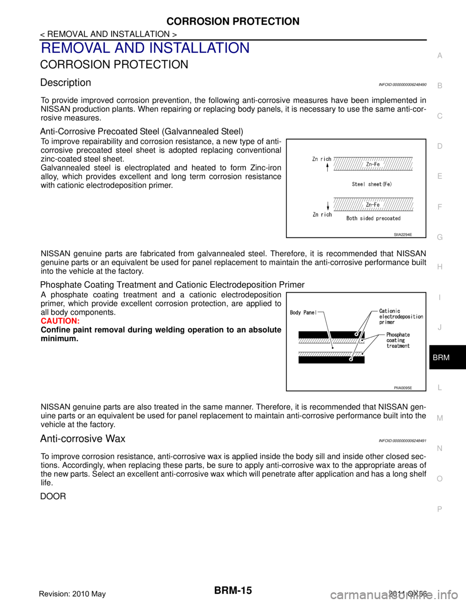
Anti-Corrosive Precoated Steel (Galvannealed Steel)
To improve repairability and corrosi on resistance, a new type of anti-
corrosive precoated steel sheet is adopted replacing conventional
zinc-coated steel sheet.
Galvannealed steel is electroplated and heated to form Zinc-iron
alloy, which provides excellent and long term corrosion resistance
with cationic electrodeposition primer.
NISSAN genuine parts are fabricated from galvannealed steel. Therefore, it is recommended that NISSAN
genuine parts or an equivalent be used for panel replacem ent to maintain the anti-corrosive performance built
into the vehicle at the factory.
Phosphate Coating Treatment and Cationic Electrodeposition Primer
A phosphate coating treatment and a cationic electrodeposition
primer, which provide excellent corrosion protection, are applied to
all body components.
CAUTION:
Confine paint removal during we lding operation to an absolute
minimum.
NISSAN genuine parts are also treated in the same manner. Therefore, it is recommended that NISSAN gen-
uine parts or an equivalent be used for panel replacement to maintain anti-corrosive performance built into the
vehicle at the factory.
Anti-corrosive WaxINFOID:0000000006248491
To improve corrosion resistance, anti-corrosive wax is applied inside the body sill and inside other closed sec-
tions. Accordingly, when replacing these parts, be sure to apply anti-corrosive wax to the appropriate areas of
the new parts. Select an excellent anti-corrosive wax which will penetrate after application and has a long shelf
life.
DOOR
SIIA2294E
PIIA0095E
Revision: 2010 May2011 QX56
Page 691 of 5598
BRM-16
< REMOVAL AND INSTALLATION >
CORROSION PROTECTION
Undercoating
INFOID:0000000006248492
The underside of the floor and wheelhouse are undercoated to prevent rust, vibration, noise and stone chip-
ping. Therefore, when such a panel is replaced or re paired, apply undercoating to that part. Use an undercoat-
ing which is rust resistant, soundproof, vibr ation-proof, shock-resistant, adhesive, and durable.
Precautions in Undercoating
1. Never apply undercoating to any place unless specif ied (such as the areas above the muffler and three
way catalyst that are subjected to heat).
2. Never undercoat the exhaust pipe or other parts that become hot.
3. Never undercoat rotating parts.
4. Apply bitumen wax after applying undercoating.
5. After putting seal on the vehicle, put undercoating on it.
B. Nozzle insert hole
Unit: mm (in)
: Anti-corrosive wax coated portions
JSKIA1888GB
Revision: 2010 May2011 QX56
Page 700 of 5598

REPLACEMENT OPERATIONSBRM-25
< REMOVAL AND INSTALLATION >
C
DE
F
G H
I
J
L
M A
B
BRM
N
O P
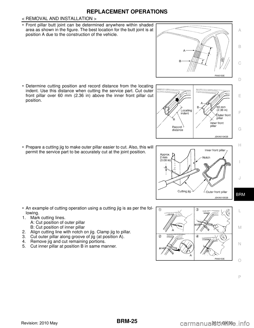
Front pillar butt joint can be determined anywhere within shaded area as shown in the figure. The best location for the butt joint is at
position A due to the construction of the vehicle.
Determine cutting position and record distance from the locating indent. Use this distance when cutting the service part. Cut outer
front pillar over 60 mm (2.36 in) above the inner front pillar cut
position.
Prepare a cutting jig to make outer pillar easier to cut. Also, this will permit the service part to be accurately cut at the joint position.
An example of cutting operation using a cutting jig is as per the fol- lowing.
1. Mark cutting lines.
A: Cut position of outer pillar
B: Cut position of inner pillar
2. Align cutting line with notch on jig. Clamp jig to pillar.
3. Cut outer pillar along groove of jig (at position A).
4. Remove jig and cut remaining portions.
5. Cut inner pillar at position B in same manner.
PIIA0150E
JSKIA0104GB
JSKIA0105GB
PIIA0153E
Revision: 2010 May2011 QX56