Page 5465 of 5598
LOW TIRE PRESSURE WARNING CONTROL UNIT
WT-15
< ECU DIAGNOSIS INFORMATION >
C
D F
G H
I
J
K L
M A
B
WT
N
O P
Te r m i n a l N o . (Wire color) Description
Condition Value (Approx.)
Signal name Input/
Output
1
(P) —CAN-L Input/
Output ——
2
(L) —CAN-H Input/
Output ——
3
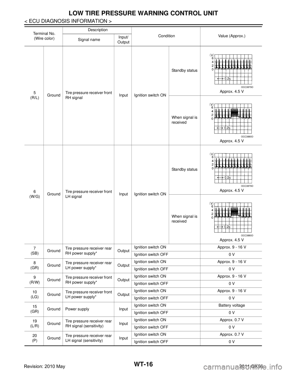
(O/L) Ground Tire pressure receiver rear
RH signal Input Ignition switch ONStandby status
Approx. 4.5 V
When signal is
received Approx. 4.5 V
4
(L) Ground
Tire pressure receiver rear
LH signal Input Ignition switch ONStandby status
Approx. 4.5 V
When signal is
received Approx. 4.5 V
OCC3879D
OCC3880D
OCC3879D
OCC3880D
Revision: 2010 May2011 QX56
Page 5466 of 5598

WT-16
< ECU DIAGNOSIS INFORMATION >
LOW TIRE PRESSURE WARNING CONTROL UNIT
5
(R/L) Ground
Tire pressure receiver front
RH signal Input Ignition switch ONStandby status
Approx. 4.5 V
When signal is
received Approx. 4.5 V
6
(W/G) Ground Tire pressure receiver front
LH signal
Input Ignition switch ONStandby status
Approx. 4.5 V
When signal is
received Approx. 4.5 V
7
(SB) Ground Tire pressure receiver rear
RH power supply*
OutputIgnition switch ON Approx. 9 - 16 V
Ignition switch OFF 0 V
8
(GR) Ground Tire pressure receiver rear
LH power supply*
OutputIgnition switch ON Approx. 9 - 16 V
Ignition switch OFF 0 V
9
(R/W) Ground Tire pressure receiver front
RH power supply*
OutputIgnition switch ON Approx. 9 - 16 V
Ignition switch OFF 0 V
10
(LG) Ground Tire pressure receiver front
LH power supply*
OutputIgnition switch ON Approx. 9 - 16 V
Ignition switch OFF 0 V
15
(GR) Ground Power supply Input Ignition switch ON Battery voltage
Ignition switch OFF 0 V
19
(L/R) Ground Tire pressure receiver rear
RH signal (sensitivity) InputIgnition switch ON Approx. 0.7 V
Ignition switch OFF 0 V
20
(P) Ground Tire pressure receiver rear
LH signal (sensitivity) InputIgnition switch ON Approx. 0.7 V
Ignition switch OFF 0 V
Te r m i n a l N o .
(Wire color) Description
Condition Value (Approx.)
Signal name Input/
Output
OCC3879D
OCC3880D
OCC3879D
OCC3880D
Revision: 2010 May2011 QX56
Page 5467 of 5598

LOW TIRE PRESSURE WARNING CONTROL UNIT
WT-17
< ECU DIAGNOSIS INFORMATION >
C
D F
G H
I
J
K L
M A
B
WT
N
O P
*: Power is supplied to the tire pressure receiver from the low tire pressure warning control unit.
DTC Inspection Priority ChartINFOID:0000000006225498
If some DTCs are displayed at the same time, per form inspections one by one based on the following priority-
chart.
21
(G/R) Ground
Tire pressure receiver front
RH signal (sensitivity) InputIgnition switch ON Approx. 0.7 V
Ignition switch OFF 0 V
22
(BR/Y) Ground
Tire pressure receiver front
LH signal (sensitivity) InputIgnition switch ON Approx. 0.7 V
Ignition switch OFF 0 V
23
(V/W) Ground Tire pressure receiver rear
RH ground
Input Always 0 V
24
(R/B) Ground
Tire pressure receiver rear
LH ground Input Always 0 V
25
(W/L) Ground Tire pressure receiver front
RH ground Input Always 0 V
26
(BR/W) GroundTire pressure receiver front
LH ground
Input Always 0 V
32
(B) Ground Ground — Always 0 V
Te r m i n a l N o .
(Wire color) Description
Condition Value (Approx.)
Signal name Input/
Output
Priority Detected items (DTC)
1 U1000 CAN COMM CIRCUIT
U1010 CONTROL UNIT (CAN)
2 C1704 LOW PRESSURE FL
C1705 LOW PRESSURE FR
C1706 LOW PRESSURE RR
C1707 LOW PRESSURE RL
3 C1755 PR RECEIV COND FL
C1756 PR RECEIV COND FR
C1757 PR RECEIV COND RR
C1758 PR RECEIV COND RL
4 C1708 [NO DATA] FL
C1709 [NO DATA] FR
C1710 [NO DATA] RR
C1711 [NO DATA] RL
5 C1716 [PRESSDATA ERR] FL
C1717 [PRESSDATA ERR] FR
C1718 [PRESSDATA ERR] RR
C1719 [PRESSDATA ERR] RL
7 C1728 RECEIVER ID NO REG
8 C1729 VHCL SPEED SIG ERR
9 C1750 [RECEIVER ERR] FL
C1751 [RECEIVER ERR] FR
C1752 [RECEIVER ERR] RR
C1753 [RECEIVER ERR] RL
10 C1754 CONT UNIT (EEPROM)
Revision: 2010 May2011 QX56
Page 5468 of 5598

WT-18
< ECU DIAGNOSIS INFORMATION >
LOW TIRE PRESSURE WARNING CONTROL UNIT
DTC Index
INFOID:0000000006225499
NOTE:
If some DTCs are displayed at the same time, refer to WT-17, "
DTC Inspection Priority Chart".
DTC Items (CONSULT-III screen terms) Reference
C1704 LOW PRESSURE FL
WT-31, "
DTC Logic"C1705 LOW PRESSURE FR
C1706 LOW PRESSURE RR
C1707 LOW PRESSURE RL
C1708 [NO DATA] FLWT-33, "
DTC Logic"C1709 [NO DATA] FR
C1710 [NO DATA] RRC1711 [NO DATA] RL
C1716 [PRESSDATA ERR] FL
WT-37, "
DTC Logic"C1717 [PRESSDATA ERR] FR
C1718 [PRESSDATA ERR] RR
C1719 [PRESSDATA ERR] RL
C1728 RECEIVER ID NO REGWT-39, "
DTC Logic"
C1729 VHCL SPEED SIG ERRWT-41, "DTC Logic"
C1750 [RECEIVER ERR] FL
WT-42, "
DTC Logic"C1751 [RECEIVER ERR] FR
C1752 [RECEIVER ERR] RR
C1753 [RECEIVER ERR] RL
C1754 CONT UNIT (EEPROM)WT-45, "
DTC Logic"
C1755 PR RECEIV COND FL
WT-47, "
DTC Logic"C1756 PR RECEIV COND FR
C1757 PR RECEIV COND RR
C1758 PR RECEIV COND RL
U1000 CAN COMM CIRCUITWT-49, "
DTC Logic"
U1010 CONTROL UNIT (CAN)WT-50, "DTC Logic"
Revision: 2010 May2011 QX56
Page 5475 of 5598

DIAGNOSIS AND REPAIR WORK FLOWWT-25
< BASIC INSPECTION >
C
DF
G H
I
J
K L
M A
B
WT
N
O P
BASIC INSPECTION
DIAGNOSIS AND REPAIR WORK FLOW
Work Flow INFOID:0000000006225501
DETAILED FLOW
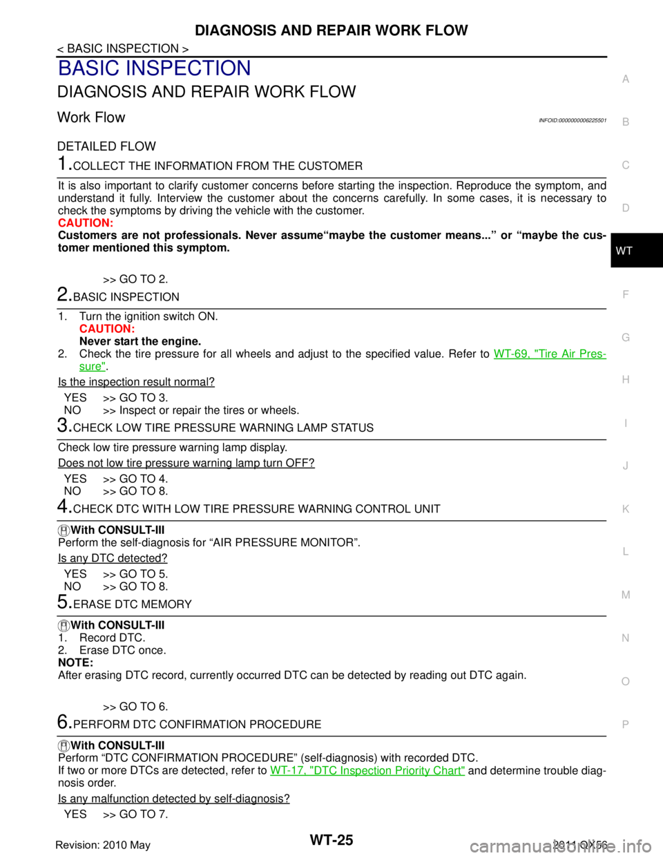
1.COLLECT THE INFORMATION FROM THE CUSTOMER
It is also important to clarify customer concerns before starting the inspection. Reproduce the symptom, and
understand it fully. Interview the customer about the concer ns carefully. In some cases, it is necessary to
check the symptoms by driving the vehicle with the customer.
CAUTION:
Customers are not professionals. Never assume“mayb e the customer means...” or “maybe the cus-
tomer mentioned this symptom.
>> GO TO 2.
2.BASIC INSPECTION
1. Turn the ignition switch ON. CAUTION:
Never start the engine.
2. Check the tire pressure for all wheels and adjust to the specified value. Refer to WT-69, "
Tire Air Pres-
sure".
Is the inspection result normal?
YES >> GO TO 3.
NO >> Inspect or repair the tires or wheels.
3.CHECK LOW TIRE PRESSURE WARNING LAMP STATUS
Check low tire pressure warning lamp display.
Does not low tire pressure warning lamp turn OFF?
YES >> GO TO 4.
NO >> GO TO 8.
4.CHECK DTC WITH LOW TIRE PR ESSURE WARNING CONTROL UNIT
With CONSULT-III
Perform the self-diagnosis fo r “AIR PRESSURE MONITOR”.
Is any DTC detected?
YES >> GO TO 5.
NO >> GO TO 8.
5.ERASE DTC MEMORY
With CONSULT-III
1. Record DTC.
2. Erase DTC once.
NOTE:
After erasing DTC record, currently occurr ed DTC can be detected by reading out DTC again.
>> GO TO 6.
6.PERFORM DTC CONFIRMATION PROCEDURE
With CONSULT-III
Perform “DTC CONFIRMATION PROCEDURE” (self-diagnosis) with recorded DTC.
If two or more DTCs are detected, refer to WT-17, "
DTC Inspection Priority Chart" and determine trouble diag-
nosis order.
Is any malfunction detected by self-diagnosis?
YES >> GO TO 7.
Revision: 2010 May2011 QX56
Page 5477 of 5598
ADDITIONAL SERVICE WHEN REPLACING LOW TIRE PRESSURE WARNING
CONTROL UNIT
WT-27
< BASIC INSPECTION >
C
DF
G H
I
J
K L
M A
B
WT
N
O P
ADDITIONAL SERVICE WHEN RE PLACING LOW TIRE PRESSURE
WARNING CONTROL UNIT
DescriptionINFOID:0000000006225502
When replacing low tire pressure warning contro l unit, transmitter ID registration is required.
Work ProcedureINFOID:0000000006225503
ADJUST THE NEUTRAL POSITION OF STEERING ANGLE SENSOR
1.PERFORM TRANSMITTER ID REGISTRATION
Perform transmitter ID registration.
>> Refer to WT-29, "
Work Procedure".
Revision: 2010 May2011 QX56
Page 5478 of 5598

WT-28
< BASIC INSPECTION >
TRANSMITTER WAKE UP OPERATION
TRANSMITTER WAKE UP OPERATION
DescriptionINFOID:0000000006225504
When replacing transmitter, always transmitter wake-up is required.
Work ProcedureINFOID:0000000006225505
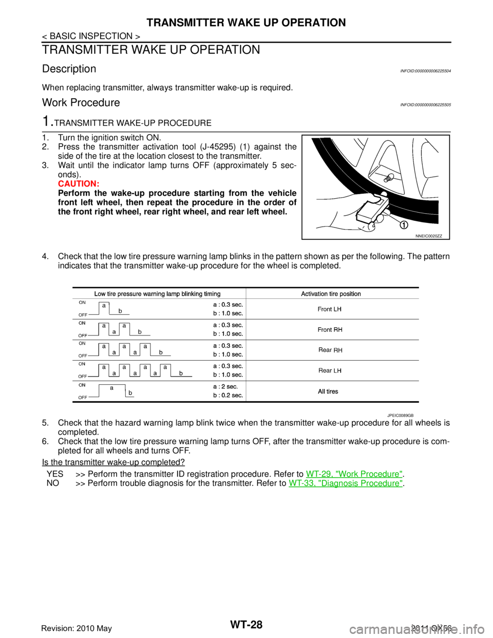
1.TRANSMITTER WAKE-UP PROCEDURE
1. Turn the ignition switch ON.
2. Press the transmitter activation tool (J-45295) (1) against the side of the tire at the location closest to the transmitter.
3. Wait until the indicator lamp turns OFF (approximately 5 sec- onds).
CAUTION:
Perform the wake-up procedure starting from the vehicle
front left wheel, then repeat the procedure in the order of
the front right wheel, rear right wheel, and rear left wheel.
4. Check that the low tire pressure warning lamp blinks in the pattern shown as per the following. The pattern
indicates that the transmitter wake- up procedure for the wheel is completed.
5. Check that the hazard warning lamp blink twice w hen the transmitter wake-up procedure for all wheels is
completed.
6. Check that the low tire pressure warning lamp turn s OFF, after the transmitter wake-up procedure is com-
pleted for all wheels and turns OFF.
Is the transmitter wake-up completed?
YES >> Perform the transmitter ID registration procedure. Refer to WT-29, "Work Procedure".
NO >> Perform trouble diagnosis for the transmitter. Refer to WT-33, "
Diagnosis Procedure".
NNEIC0020ZZ
JPEIC0089GB
Revision: 2010 May2011 QX56
Page 5479 of 5598

ID REGISTRATIONWT-29
< BASIC INSPECTION >
C
DF
G H
I
J
K L
M A
B
WT
N
O P
ID REGISTRATION
DescriptionINFOID:0000000006225506
When replacing or rotating wheels, replacing transmitter or low tire pressure warning control unit, always
transmitter ID registration is required.
Work ProcedureINFOID:0000000006225507
1.CONFIRMATION OF TRANSMITTER ACTIVATION TOOL USE
Check method of ID registration procedure.
Is the transmitter activation tool (J-45295) us ed for the transmitter ID registration procedure?
YES >> GO TO 2.
NO >> GO TO 3.
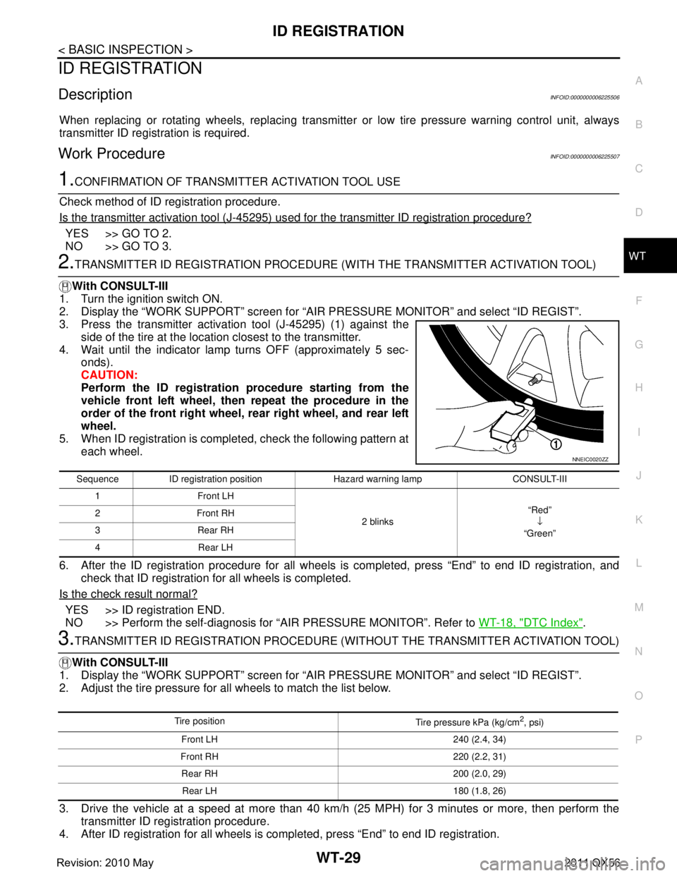
2.TRANSMITTER ID REGISTRATION PROCEDURE (W ITH THE TRANSMITTER ACTIVATION TOOL)
With CONSULT-III
1. Turn the ignition switch ON.
2. Display the “WORK SUPPORT” screen for “AIR PRESSURE MONITOR” and select “ID REGIST”.
3. Press the transmitter activation tool (J-45295) (1) against the
side of the tire at the location closest to the transmitter.
4. Wait until the indicator lamp turns OFF (approximately 5 sec- onds).
CAUTION:
Perform the ID registration procedure starting from the
vehicle front left wheel, then repeat the procedure in the
order of the front right wheel, rear right wheel, and rear left
wheel.
5. When ID registration is completed, check the following pattern at
each wheel.
6. After the ID registration procedure for all wheels is completed, press “End” to end ID registration, and
check that ID registration for all wheels is completed.
Is the check result normal?
YES >> ID registration END.
NO >> Perform the self-diagnosis for “AIR PRESSURE MONITOR”. Refer to WT-18, "
DTC Index".
3.TRANSMITTER ID REGISTRATION PROCEDURE (WITHOUT THE TRANSMITTER ACTIVATION TOOL)
With CONSULT-III
1. Display the “WORK SUPPORT” screen for “AIR PRESSURE MONITOR” and select “ID REGIST”.
2. Adjust the tire pressure for all wheels to match the list below.
3. Drive the vehicle at a speed at more than 40 km/h (25 MPH) for 3 minutes or more, then perform the
transmitter ID registration procedure.
4. After ID registration for all wheels is completed, press “End” to end ID registration.
Sequence ID registration position Hazard warning lamp CONSULT-III
1 Front LH
2 blinks“Red”
↓
“Green”
2Front RH
3Rear RH
4 Rear LH
NNEIC0020ZZ
Tire position
Tire pressure kPa (kg/cm2, psi)
Front LH 240 (2.4, 34)
Front RH 220 (2.2, 31) Rear RH 200 (2.0, 29)Rear LH 180 (1.8, 26)
Revision: 2010 May2011 QX56