2011 INFINITI QX56 fuel pump
[x] Cancel search: fuel pumpPage 2624 of 5598
EM-62
< REMOVAL AND INSTALLATION >
TIMING CHAIN
Removal and Installation
INFOID:0000000006289566
REMOVAL
1. Release fuel pressure. Refer to EC-153, "Work Procedure".
2. Drain engine coolant from radiator. Refer to CO-8, "
Draining".
3. Remove fan shroud (lower). Refer to CO-13, "
Exploded View".
4. Remove fan bracket. Refer to CO-16, "
Exploded View".
5. Remove drive belt auto-tensioner. Refer to EM-26, "
Exploded View".
6. Remove oil level gauge and oil level gauge guide. Refer to EM-57, "
Exploded View".
7. Move power steering oil pump to the posit ion without the hindrance for work. Refer to ST-48, "
Exploded
View".
8. Remove alternator, alternator bracket and alternator stay. Refer to CHG-25, "
Exploded View".
9. Move power steering reservoir tank to the position without the hindrance for work, and then remove Res- ervoir tank bracket. Refer to ST-54, "
Exploded View".
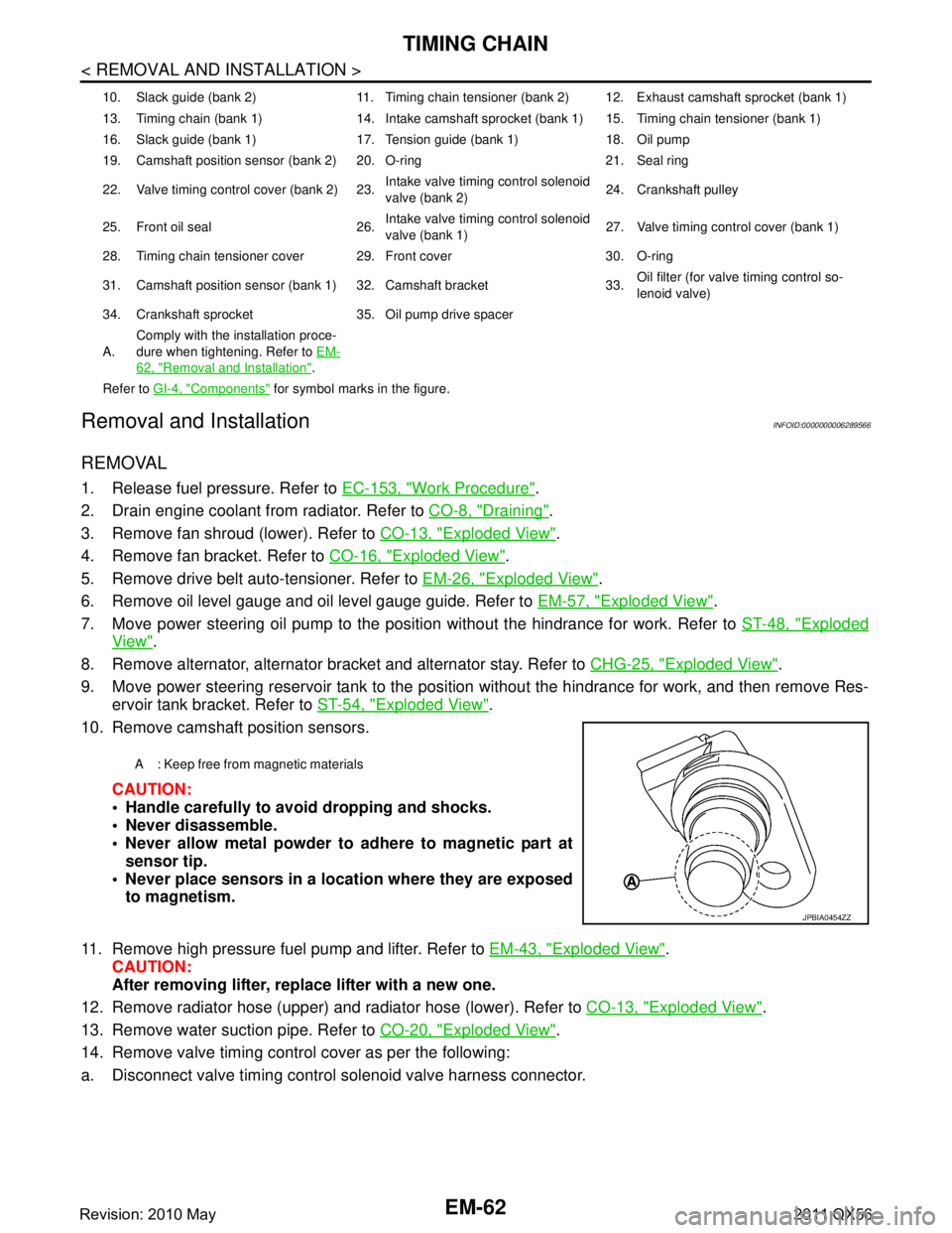
10. Remove camshaft position sensors.
CAUTION:
Handle carefully to avoid dropping and shocks.
Never disassemble.
Never allow metal powder to adhere to magnetic part atsensor tip.
Never place sensors in a lo cation where they are exposed
to magnetism.
11. Remove high pressure fuel pump and lifter. Refer to EM-43, "
Exploded View".
CAUTION:
After removing lifter, replace lifter with a new one.
12. Remove radiator hose (upper) and radiator hose (lower). Refer to CO-13, "
Exploded View".
13. Remove water suction pipe. Refer to CO-20, "
Exploded View".
14. Remove valve timing control cover as per the following:
a. Disconnect valve timing control solenoid valve harness connector.
10. Slack guide (bank 2) 11. Timing chain tensioner (bank 2) 12. Exhaust camshaft sprocket (bank 1)
13. Timing chain (bank 1) 14. Intake camshaft sprocket (bank 1) 15. Timing chain tensioner (bank 1)
16. Slack guide (bank 1) 17. Tension guide (bank 1) 18. Oil pump
19. Camshaft position sensor (bank 2) 20. O-ring 21. Seal ring
22. Valve timing control cover (bank 2) 23. Intake valve timing control solenoid
valve (bank 2)24. Crankshaft pulley
25. Front oil seal 26. Intake valve timing control solenoid
valve (bank 1)27. Valve timing control cover (bank 1)
28. Timing chain tensioner cover 29. Front cover 30. O-ring
31. Camshaft position sensor (bank 1) 32. Camshaft bracket 33. Oil filter (for valve timing control so-
lenoid valve)
34. Crankshaft sprocket 35. Oil pump drive spacer
A. Comply with the installation proce-
dure when tightening. Refer to
EM-
62, "Removal and Installation".
Refer to GI-4, "
Components" for symbol marks in the figure.
A : Keep free from magnetic materials
JPBIA0454ZZ
Revision: 2010 May2011 QX56
Page 2626 of 5598
EM-64
< REMOVAL AND INSTALLATION >
TIMING CHAIN
24. Remove oil pump and oil pump drive spacer.
25. Remove front oil seal from front cover using suitable tool. Use screwdriver for removal.
CAUTION:
Be careful not to damage front cover.
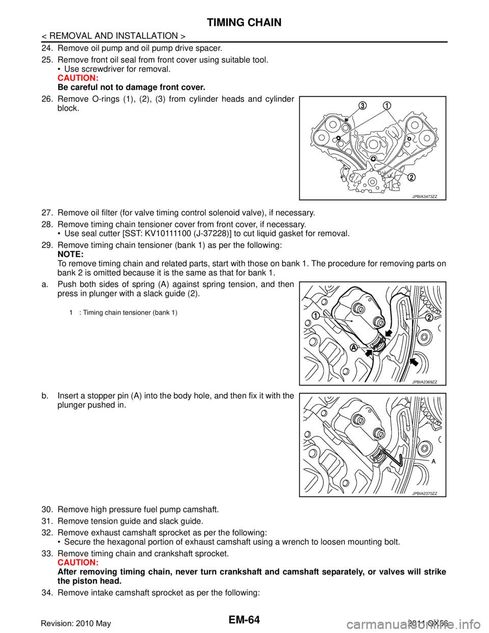
26. Remove O-rings (1), (2), (3) from cylinder heads and cylinder block.
27. Remove oil filter (for valve timing control solenoid valve), if necessary.
28. Remove timing chain tensioner cover from front cover, if necessary. Use seal cutter [SST: KV10111100 (J-37228)] to cut liquid gasket for removal.
29. Remove timing chain tensioner (bank 1) as per the following: NOTE:
To remove timing chain and related parts, start with those on bank 1. The procedure for removing parts on
bank 2 is omitted because it is the same as that for bank 1.
a. Push both sides of spring (A) against spring tension, and then press in plunger with a slack guide (2).
b. Insert a stopper pin (A) into the body hole, and then fix it with the
plunger pushed in.
30. Remove high pressure fuel pump camshaft.
31. Remove tension guide and slack guide.
32. Remove exhaust camshaft sprocket as per the following: Secure the hexagonal portion of exhaust camshaf t using a wrench to loosen mounting bolt.
33. Remove timing chain and crankshaft sprocket. CAUTION:
After removing timing chain, never turn cranksh aft and camshaft separately, or valves will strike
the piston head.
34. Remove intake camshaft sprocket as per the following:
JPBIA3473ZZ
1 : Timing chain tensioner (bank 1)
JPBIA2369ZZ
JPBIA2370ZZ
Revision: 2010 May2011 QX56
Page 2628 of 5598
EM-66
< REMOVAL AND INSTALLATION >
TIMING CHAIN
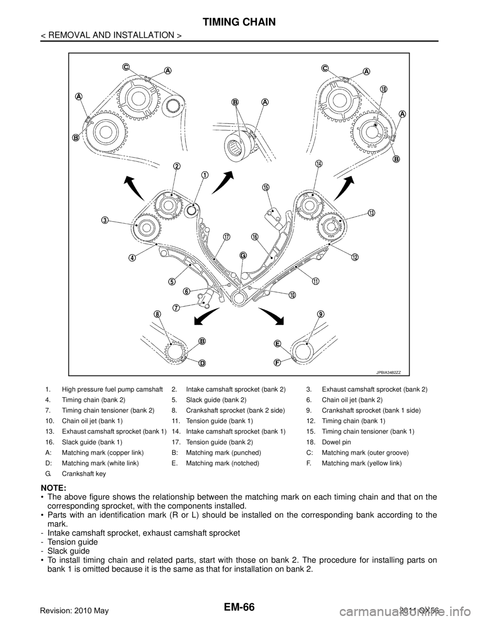
NOTE:
The above figure shows the relationship between the matching mark on each timing chain and that on the
corresponding sprocket, with the components installed.
Parts with an identification mark (R or L) should be installed on the corresponding bank according to the
mark.
- Intake camshaft sprocket, exhaust camshaft sprocket
- Tension guide
- Slack guide
To install timing chain and related parts, start with those on bank 2. The procedure for installing parts on
bank 1 is omitted because it is the same as that for installation on bank 2.
1. High pressure fuel pump camshaft 2. Intake camshaft sprocket (bank 2) 3. Exhaust camshaft sprocket (bank 2)
4. Timing chain (bank 2) 5. Slack guide (bank 2) 6. Chain oil jet (bank 2)
7. Timing chain tensioner (bank 2) 8. Crankshaft sprocket (bank 2 side) 9. Crankshaft sprocket (bank 1 side)
10. Chain oil jet (bank 1) 11. Tension guide (bank 1) 12. Timing chain (bank 1)
13. Exhaust camshaft sprocket (bank 1) 14. Intake camshaft sprocket (bank 1) 15. Timing chain tensioner (bank 1)
16. Slack guide (bank 1) 17. Tension guide (bank 2) 18. Dowel pin
A: Matching mark (copper link) B: Matching mark (punched) C: Matching mark (outer groove)
D: Matching mark (white link) E. Matching mark (notched) F. Matching mark (yellow link)
G. Crankshaft key
JPBIA3482ZZ
Revision: 2010 May2011 QX56
Page 2629 of 5598
TIMING CHAINEM-67
< REMOVAL AND INSTALLATION >
C
DE
F
G H
I
J
K L
M A
EM
NP
O
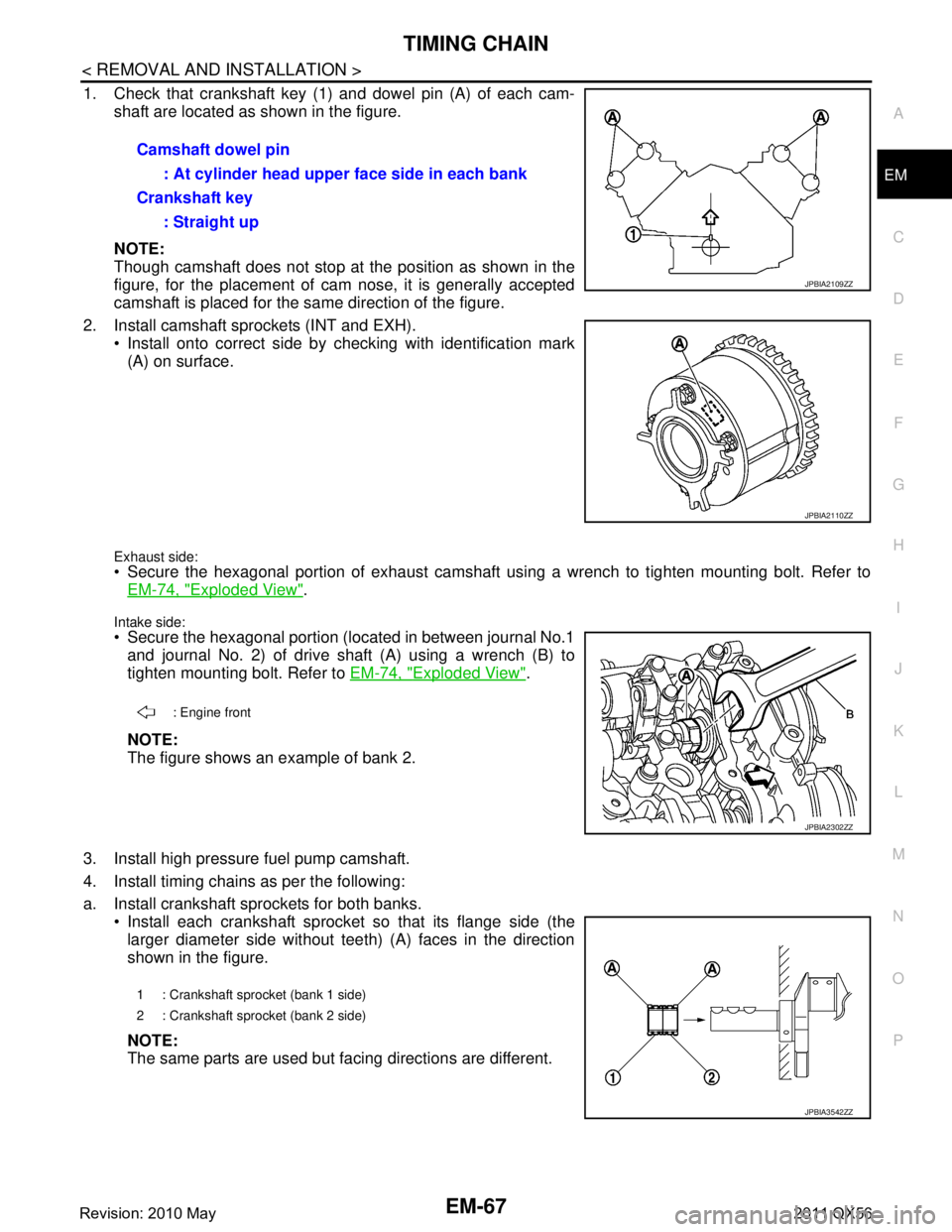
1. Check that crankshaft key (1) and dowel pin (A) of each cam-
shaft are located as shown in the figure.
NOTE:
Though camshaft does not stop at the position as shown in the
figure, for the placement of cam nose, it is generally accepted
camshaft is placed for the same direction of the figure.
2. Install camshaft sprockets (INT and EXH). Install onto correct side by checking with identification mark(A) on surface.
Exhaust side: Secure the hexagonal portion of exhaust camshaft using a wrench to tighten mounting bolt. Refer toEM-74, "
Exploded View".
Intake side:
Secure the hexagonal portion (located in between journal No.1and journal No. 2) of drive shaft (A) using a wrench (B) to
tighten mounting bolt. Refer to EM-74, "
Exploded View".
NOTE:
The figure shows an example of bank 2.
3. Install high pressure fuel pump camshaft.
4. Install timing chains as per the following:
a. Install crankshaft sprockets for both banks. Install each crankshaft sprocket so that its flange side (thelarger diameter side without teeth) (A) faces in the direction
shown in the figure.
NOTE:
The same parts are used but facing directions are different.Camshaft dowel pin
: At cylinder head upper face side in each bank
Crankshaft key : Straight up
JPBIA2109ZZ
JPBIA2110ZZ
: Engine front
JPBIA2302ZZ
1 : Crankshaft sprocket (bank 1 side)
2 : Crankshaft sprocket (bank 2 side)
JPBIA3542ZZ
Revision: 2010 May2011 QX56
Page 2633 of 5598
TIMING CHAINEM-71
< REMOVAL AND INSTALLATION >
C
DE
F
G H
I
J
K L
M A
EM
NP
O
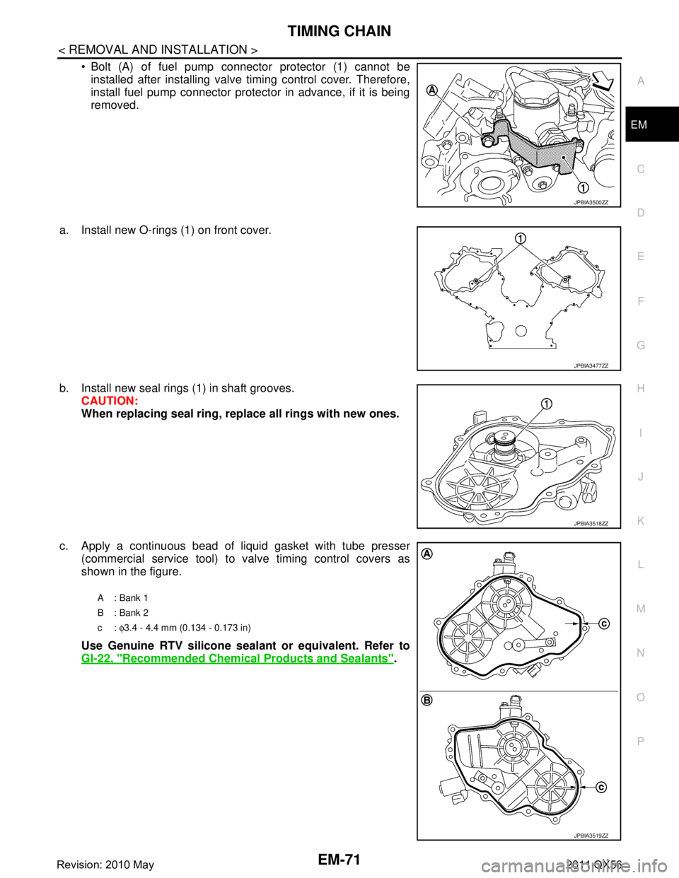
Bolt (A) of fuel pump connector protector (1) cannot be
installed after installing valve timing control cover. Therefore,
install fuel pump connector protector in advance, if it is being
removed.
a. Install new O-rings (1) on front cover.
b. Install new seal rings (1) in shaft grooves. CAUTION:
When replacing seal ring, replace all rings with new ones.
c. Apply a continuous bead of liquid gasket with tube presser (commercial service tool) to valve timing control covers as
shown in the figure.
Use Genuine RTV silicone seal ant or equivalent. Refer to
GI-22, "
Recommended Chemical Products and Sealants".
JPBIA3500ZZ
JPBIA3477ZZ
JPBIA3518ZZ
A : Bank 1
B : Bank 2
c: φ3.4 - 4.4 mm (0.134 - 0.173 in)
JPBIA3519ZZ
Revision: 2010 May2011 QX56
Page 2663 of 5598
ENGINE ASSEMBLYEM-101
< UNIT REMOVAL AND INSTALLATION >
C
DE
F
G H
I
J
K L
M A
EM
NP
O
5. Remove A/T assembly. Refer to
TM-205, "2WD : Exploded View" (2WD models) or TM-208, "4WD :
Exploded View" (4WD models).
6. Remove steering gear assembly. Refer to ST-41, "
Exploded View".
7. Remove front final drive assembly. Refer to DLN-162, "
Exploded View".
8. Remove exhaust manifold. Refer to EM-40, "
Exploded View".
9. Remove alternator. Refer to CHG-25, "
Exploded View".
Engine Room LH
1. Remove air cleaner and air duct. Refer to EM-27, "Exploded View".
2. Remove A/C compressor. Refer to HA-30, "
Exploded View".
3. Disconnect fuel feed hose and EVAP hose. Refer to EM-43, "
Exploded View".
CAUTION:
Fit plugs onto disconnected hoses to prevent fuel leakage.
Engine Room RH
1. Remove power steering oil pump and reservoir tank. Refer to ST-48, "Exploded View".
2. Disconnect heater hose at heater core side, and fit a plug onto hose end to prevent engine coolant leak-
age.
3. Disconnect ground cable.
4. Disconnect all clips and connectors of the engine harness from vehicle side.
Removal Work
1. Install alternator bracket. Refer to CHG-25, "Exploded View".
Temporarily tighten mounting bolts.
2. Remove intake manifold. Refer to EM-30, "
Exploded View".
3. Remove starter motor. Refer to STR-17, "
Exploded View".
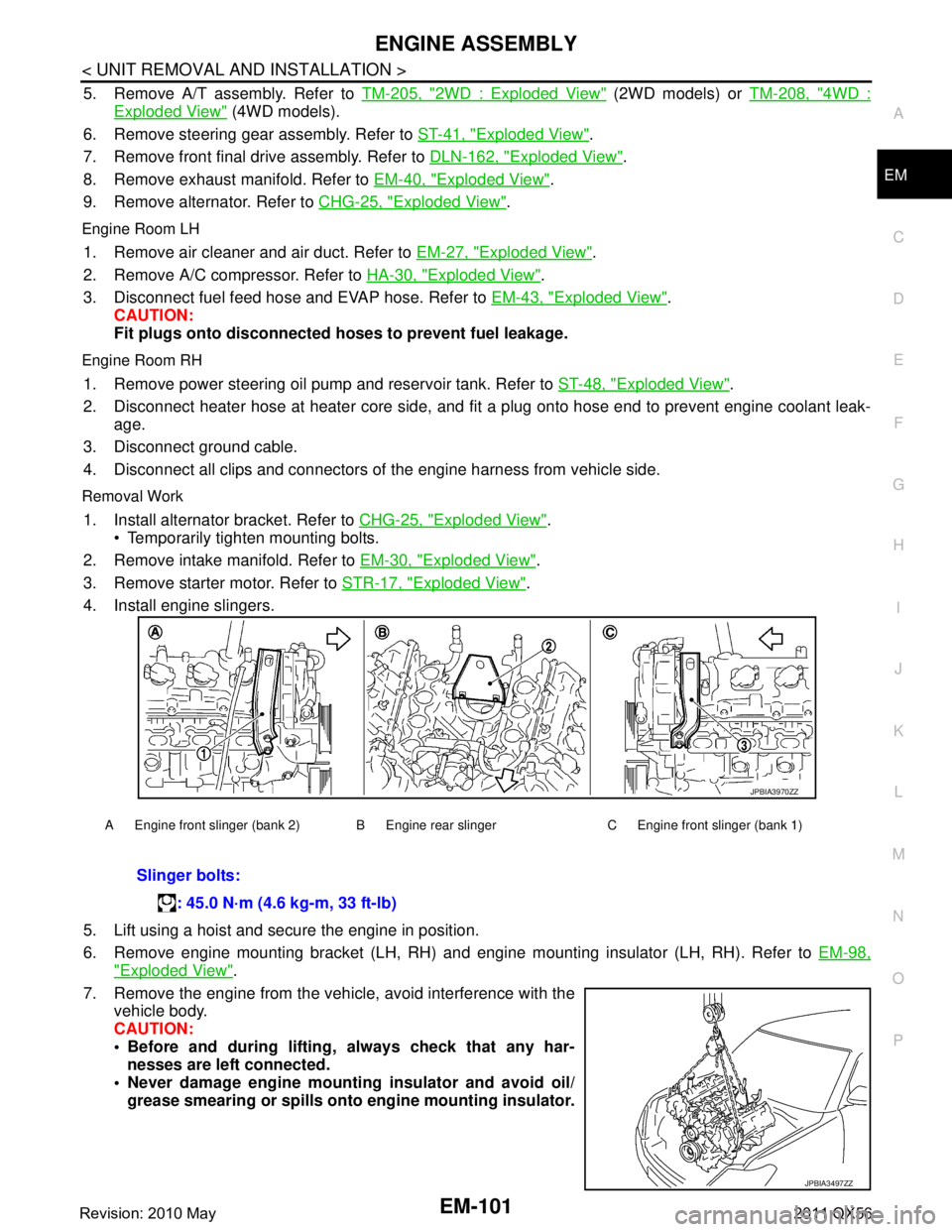
4. Install engine slingers.
5. Lift using a hoist and secure the engine in position.
6. Remove engine mounting bracket (LH, RH) and engine mounting insulator (LH, RH). Refer to EM-98,
"Exploded View".
7. Remove the engine from the vehi cle, avoid interference with the
vehicle body.
CAUTION:
Before and during lifting, always check that any har-
nesses are left connected.
Never damage engine mounti ng insulator and avoid oil/
grease smearing or spills onto engine mounting insulator.
A Engine front slinger (bank 2) B Engine rear slinger C Engine front slinger (bank 1)
Slinger bolts:
: 45.0 N·m (4.6 kg-m, 33 ft-lb)
JPBIA3970ZZ
JPBIA3497ZZ
Revision: 2010 May2011 QX56
Page 2930 of 5598
FL-1
ENGINE
C
DE
F
G H
I
J
K L
M
SECTION FL
A
FL
N
O P
CONTENTS
FUEL SYSTEM
PRECAUTION ................ ...............................2
PRECAUTIONS .............................................. .....2
General Precautions ........................................... ......2
PREPARATION ............................................3
PREPARATION .............................................. .....3
Special Service Tool ........................................... ......3
Commercial Service Tools ........................................3
PERIODIC MAINTENANCE ..........................4
FUEL SYSTEM ............................................... .....4
Inspection ............................................................ ......4
Quick Connector .......................................................4
REMOVAL AND INSTALLATION ................5
FUEL LEVEL SENSOR UNIT, FUEL FILTER
AND FUEL PUMP ASSEMBLY ..................... .....
5
Exploded View .................................................... ......5
Removal and Installation ..................................... .....5
Inspection .................................................................7
FUEL TANK ..................................... ..................8
Exploded View ..................................................... .....8
Removal and Installation ..........................................8
Inspection .................................................................9
EVAP CANISTER ..............................................10
Exploded View .........................................................10
Hydraulic Layout ......................................................10
Removal and Installation .........................................12
Disassembly and Assembly .....................................12
Inspection ................................................................12
SERVICE DATA AND SPECIFICATIONS
(SDS) ............... .............................................
13
SERVICE DATA AND SPECIFICATIONS
(SDS) .................................................................
13
Fuel Tank ............................................................. ....13
Revision: 2010 May2011 QX56
Page 2934 of 5598
FUEL LEVEL SENSOR UNIT, FUEL FILTER AND FUEL PUMP ASSEMBLY
FL-5
< REMOVAL AND INSTALLATION >
C
D E
F
G H
I
J
K L
M A
FL
NP
O
REMOVAL AND INSTALLATION
FUEL LEVEL SENSOR UNIT, FUEL FI
LTER AND FUEL PUMP ASSEMBLY
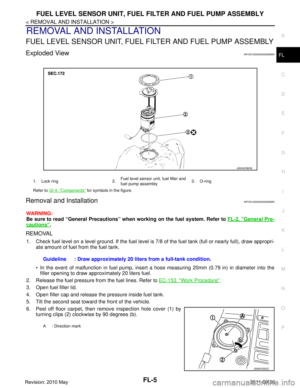
Exploded ViewINFOID:0000000006289684
Removal and InstallationINFOID:0000000006289685
WARNING:
Be sure to read “General Precautions” wh en working on the fuel system. Refer to FL-2, "
General Pre-
cautions".
REMOVAL
1. Check fuel level on a level ground. If the fuel level is 7/8 of the fuel tank (full or nearly full), draw appropri-
ate amount of fuel from the fuel tank.
In the event of malfunction in fuel pump, insert a hose measuring 20mm (0.79 in) in diameter into the
filler opening to draw approximately 20 liters fuel.
2. Release the fuel pressure from the fuel lines. Refer to EC-153, "
Work Procedure".
3. Open fuel filler lid.
4. Open filler cap and release the pressure inside fuel tank.
5. Tilt the second seat toward the front of the vehicle.
6. Peel off floor carpet, then remove inspection hole cover (1) by turning clips (2) clockwise by 90 degrees (b).
1. Lock ring 2. Fuel level sensor unit, fuel filter and
fuel pump assembly3. O-ring
Refer to GI-4, "
Components" for symbols in the figure.
JSBIA0298GB
Guideline : Draw approximately 20 li ters from a full-tank condition.
A : Direction mark
JSBIA0300ZZ
Revision: 2010 May2011 QX56