Page 69 of 408
Safety system of your vehicle
52
3
C040800AFD
Why didn’t my air bag go off in a
collision? (Inflation and non-infla-
tion conditions of the air bag)
There are many types of accidents in
which the air bag would not be expect-
ed to provide additional protection.
These include rear impacts, second or
third collisions in multiple impact
accidents, as well as low speed
impacts. In other words, just because
your vehicle is damaged and even if it
is totally unusable, don’t be surprised
that the air bags did not inflate.
Air bag collision sensors
(1) SRS control module /
Rollover sensor
(2) Front impact sensor (3) Side impact sensor
(4) Side impact sensor
OCM030040N/OCM030041/OCM030042/OXM039043/OXM039044
1234
Page 70 of 408

353
Safety system of your vehicle
C040801AUN
Air bag inflation conditions
Front air bags
Front air bags are designed to inflate in a
frontal collision depending on the intensi-
ty, speed or angles of impact of the front
collision.
WARNING
Do not hit or allow any objects toimpact the locations where air bag
or sensors are installed.
This may cause unexpected air
bag deployment, which could
result in serious personal injury
or death.
If the installation location or angle of the sensors is altered in
any way, the air bags may deploy
when they should not or they may
not deploy when they should,
causing severe injury or death.
Therefore, do not try to perform
maintenance on or around the air
bag sensors. Have the vehicle
checked and repaired by an
authorized HYUNDAI dealer.
(Continued)
(Continued)
Problems may arise if the sensorinstallation angles are changed
due to the deformation of the
front bumper, body or front doors
and/or C pillars where side colli-
sion sensors are installed. Have
the vehicle checked and repaired
by an authorized HYUNDAI deal-
er.
Your vehicle has been designed to absorb impact and deploy the
air bag(s) in certain collisions.
Installing bumper guards (or side
step or running board) or replac-
ing a bumper (or front door) with
non-genuine parts may adversely
affect your vehicles collision and
air bag deployment performance.
WARNING
If your vehicle is equipped with side
and curtain air bag, set the ignition
switch to OFF or ACC position
when the vehicle is being towed.
The side and curtain air bag may
deploy when the ignitions is ON,
and the rollover sensor detects the
situation as a rollover.
1VQA2084
Page 71 of 408

Safety system of your vehicle
54
3
Side impact and curtain air bags
Side impact and curtain air bags are
designed to inflate when an impact is
detected by side collision sensors
depending on the strength, speed or
angles of impact resulting from a side
impact collision. Also, the side impact and curtain air bags
are designed to inflate when a rollover is
detected by a rollover sensor.
Although the front air bags (driver’s and
front passenger’s air bags) are designed
to inflate only in frontal collisions, they
also may inflate in other types of colli-
sions if the front impact sensors detect a
sufficient impact. Side impact and curtain
air bags are designed to inflate only in
side impact collisions or rollovers. But
they may inflate in other type of collisions
or similar rollover situations, if the side
impact sensors or rollover sensor detect
a sufficient impact or rollover.
If the vehicle chassis is impacted by
bumps or objects on unimproved roads,
the air bags may deploy. Drive carefully
on unimproved roads or on surfaces not
designed for vehicle traffic to prevent
unintended air bag deployment.
C040802AUN
Air bag non-inflation conditions
In certain low-speed collisions the air
bags may not deploy. The air bags are
designed not to deploy in such cases
because they may not provide benefits
beyond the protection of the seat belts
in such collisions.
1VQA2086
OVQ036018N
OCM030305
Page 112 of 408
433
Features of your vehicle
To adjust the Zone setting:
1. Determine the desired Zone Numberbased upon your current location on
the Zone Map.
2. Press and hold the button for more than 3 but less than 6 seconds, the
current Zone Number will appear on
the display.
3. Pressing and holding the button again will cause the numbers to incre-
ment (Note: they will repeat …13, 14,
15, 1, 2, …). Releasing the button
when the desired Zone Number
appears on the display will set the new
Zone.
4. Within about 5 seconds the compass will start displaying a compass head-
ing again.
There are some conditions that can
cause changes to the vehicle magnets,
such as installing a ski rack or a CB
antenna. Body repair work on the vehicle
can also cause changes to the vehicle's
magnetic field. In these situations, the
compass will need to be re-calibrated to
quickly correct for these changes. To re-
calibrate the compass:
B520C05NF
Page 126 of 408

447
Features of your vehicle
✽
✽NOTICE
• If the vehicle is not on level ground or
the battery power has been interrupt-
ed, the “Distance to empty” function
may not operate correctly.
The trip computer may not register
additional fuel if less than 1.6 gallons
(6 liters) of fuel are added to the vehi-
cle.
• The fuel consumption and distance to empty values may vary significantly
based on driving conditions, driving
habits, and condition of the vehicle.
• The distance to empty value is an esti- mate of the available driving distance.
This value may differ from the actual
driving distance available.
Average speed (if equipped)
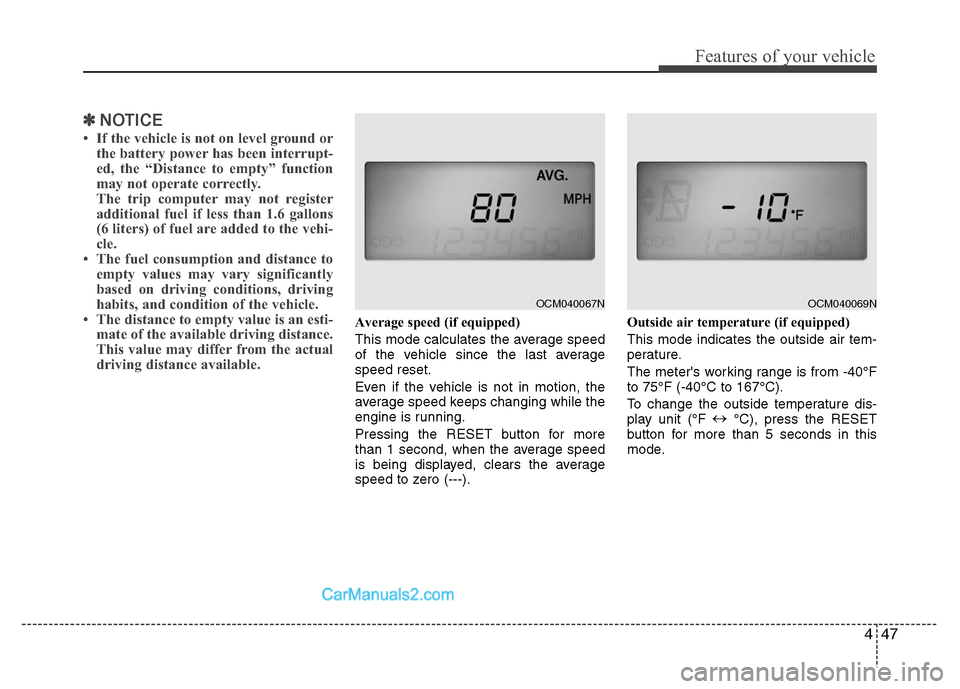
This mode calculates the average speed
of the vehicle since the last average
speed reset.
Even if the vehicle is not in motion, the
average speed keeps changing while the
engine is running.
Pressing the RESET button for more
than 1 second, when the average speed
is being displayed, clears the average
speed to zero (---). Outside air temperature (if equipped)
This mode indicates the outside air tem-
perature.
The meter's working range is from -40°F
to 75°F (-40°C to 167°C).
To change the outside temperature dis-
play unit (°F
↔
°C), press the RESET
button for more than 5 seconds in this
mode.
OCM040067N
OCM040069N
Page 146 of 408
467
Features of your vehicle
MANUAL CLIMATE CONTROL SYSTEM (IF EQUIPPED)
OCM040201N
1. Fan speed control knob
2. Air conditioning button (if equipped)
3. Mode selection button
4. OFF button
5. Air intake control button
6. Temperature control knob
7. MAX A/C button
8. Front windshield defroster button
9. Rear window defroster button
Page 147 of 408

Features of your vehicle
68
4
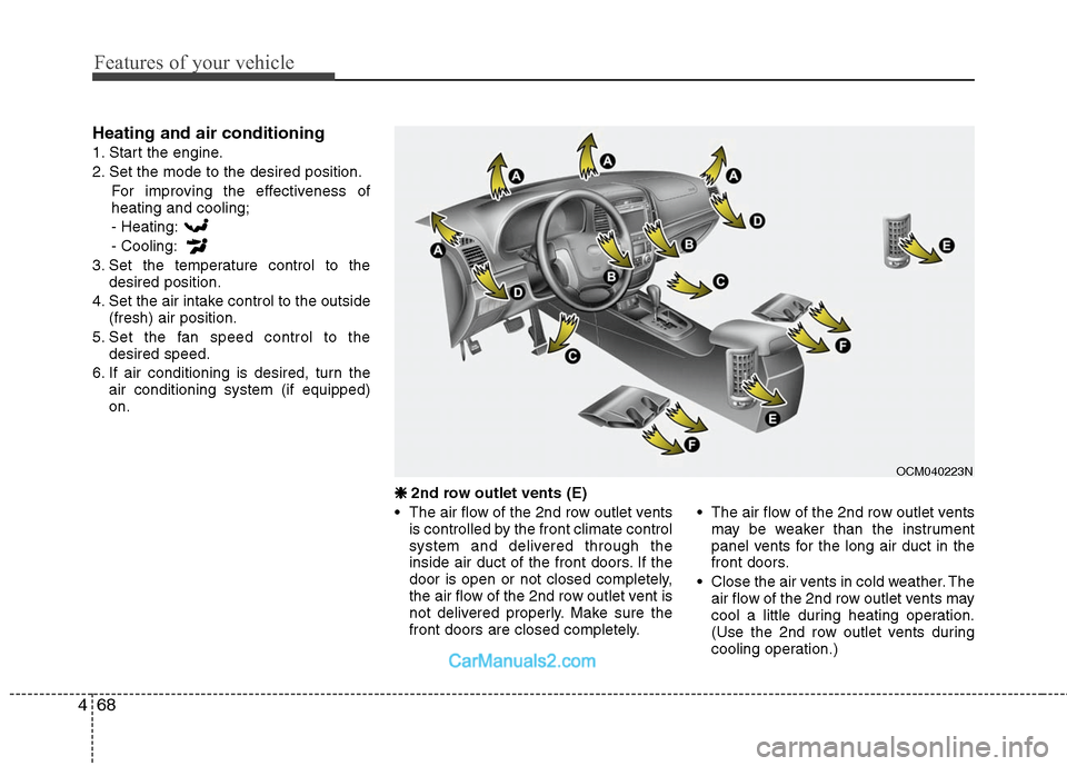
Heating and air conditioning
1. Start the engine.
2. Set the mode to the desired position.
For improving the effectiveness of
heating and cooling;
- Heating:
- Cooling:
3. Set the temperature control to the desired position.
4. Set the air intake control to the outside (fresh) air position.
5. Set the fan speed control to the desired speed.
6. If air conditioning is desired, turn the air conditioning system (if equipped)
on.
❈ ❈
2nd row outlet vents (E)
• The air flow of the 2nd row outlet vents is controlled by the front climate control
system and delivered through the
inside air duct of the front doors. If the
door is open or not closed completely,
the air flow of the 2nd row outlet vent is
not delivered properly. Make sure the
front doors are closed completely. The air flow of the 2nd row outlet vents
may be weaker than the instrument
panel vents for the long air duct in the
front doors.
Close the air vents in cold weather. The air flow of the 2nd row outlet vents may
cool a little during heating operation.
(Use the 2nd row outlet vents during
cooling operation.)
OCM040223N
Page 148 of 408

469
Features of your vehicle
Mode selection
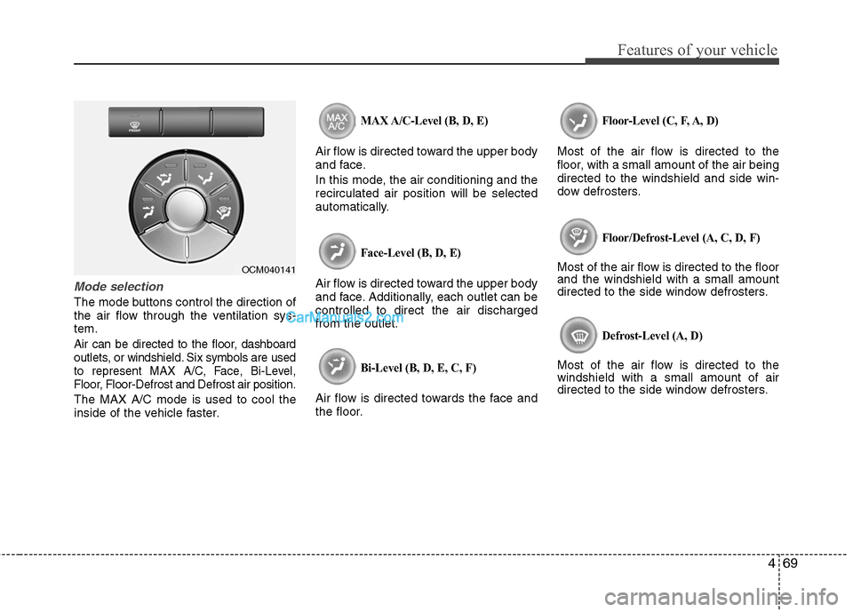
The mode buttons control the direction of
the air flow through the ventilation sys-
tem.
Air can be directed to the floor, dashboard
outlets, or windshield. Six symbols are used
to represent MAX A/C, Face, Bi-Level,
Floor, Floor-Defrost and Defrost air position.
The MAX A/C mode is used to cool the
inside of the vehicle faster.
MAX A/C-Level (B, D, E)
Air flow is directed toward the upper body
and face.
In this mode, the air conditioning and the
recirculated air position will be selected
automatically.
Face-Level (B, D, E)
Air flow is directed toward the upper body
and face. Additionally, each outlet can be
controlled to direct the air discharged
from the outlet.
Bi-Level (B, D, E, C, F)
Air flow is directed towards the face and
the floor.
Floor-Level (C, F, A, D)
Most of the air flow is directed to the
floor, with a small amount of the air being
directed to the windshield and side win-
dow defrosters.
Floor/Defrost-Level (A, C, D, F)
Most of the air flow is directed to the floor
and the windshield with a small amount
directed to the side window defrosters.
Defrost-Level (A, D)
Most of the air flow is directed to the
windshield with a small amount of air
directed to the side window defrosters.
OCM040141