Page 15 of 408
Your vehicle at a glance
2
2
INTERIOR OVERVIEW
1. Door lock/unlock button ............................4-8
2. Outside rearview mirror control switch* .....4-38
3. Central door lock switch* ..........................4-8
4. Power window lock button* .....................4-15
5. Power window switches ..........................4-13
6. Fuse box ..................................................7-47
7. ESC OFF button .....................................5-28
8. AWD Lock button ....................................5-17
9. Instrument panel illumination..................4-41
10. Front fog light button* ...........................4-60
11. AC inverter button* ...............................4-93
12. Hood release lever ...............................4-17
13. Steering wheel tilt .................................4-26
14. Seat ........................................................3-2
* : if equipped
OCM010001N
B010000AFD
Page 17 of 408
Your vehicle at a glance
4
2
ENGINE COMPARTMENT
OXM079001
1. Engine coolant reservoir ..................7-16
2. Engine oil filler cap ..........................7-14
3. Brake fluid reservoir.........................7-18
4. Air cleaner .......................................7-22
5. Fuse box ..........................................7-47
6. Negative battery terminal ................7-29
7. Positive battery terminal ..................7-29
8. Radiator cap ....................................7-17
9. Engine oil dipstick ............................7-14
10. Power steering fluid reservoir ........7-19
11. Windshield washer fluid reservoir ..7-20
* The actual engine room in the vehicle may differ from the illustration.
Page 56 of 408

339
Safety system of your vehicle
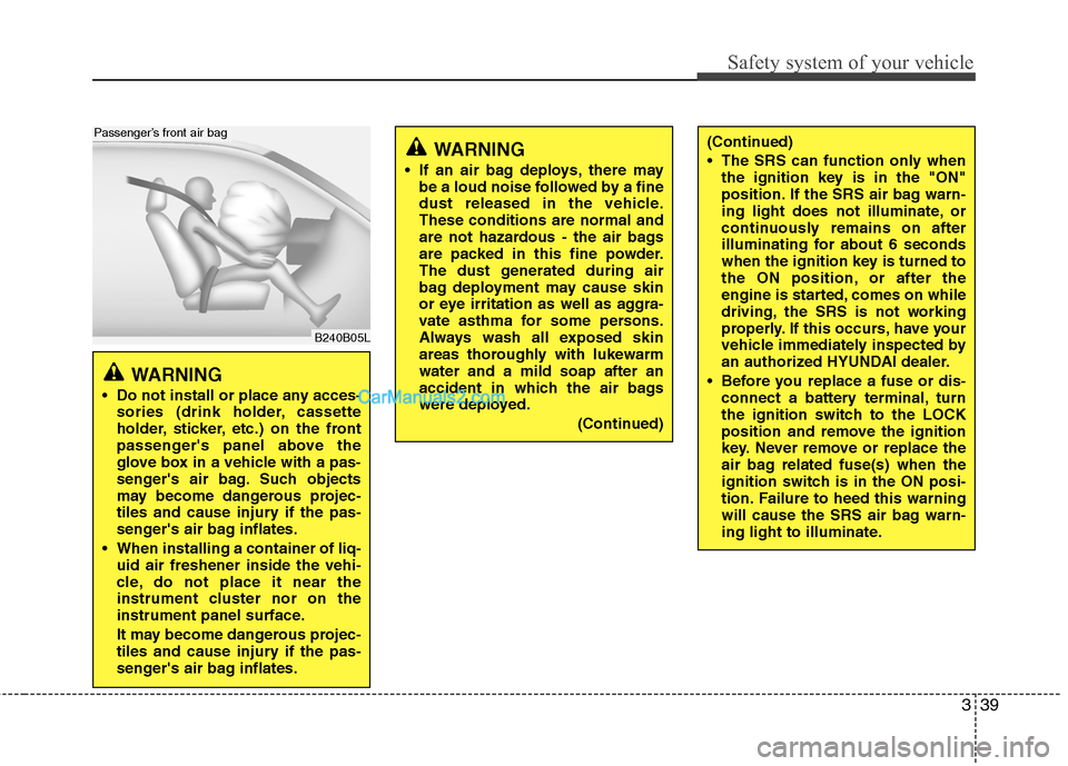
B240B05L
Passenger’s front air bag
WARNING
Do not install or place any acces-sories (drink holder, cassette
holder, sticker, etc.) on the front
passenger's panel above the
glove box in a vehicle with a pas-
senger's air bag. Such objects
may become dangerous projec-
tiles and cause injury if the pas-
senger's air bag inflates.
When installing a container of liq- uid air freshener inside the vehi-
cle, do not place it near the
instrument cluster nor on the
instrument panel surface.
It may become dangerous projec-
tiles and cause injury if the pas-
senger's air bag inflates.
WARNING
If an air bag deploys, there maybe a loud noise followed by a fine
dust released in the vehicle.
These conditions are normal and
are not hazardous - the air bags
are packed in this fine powder.
The dust generated during air
bag deployment may cause skin
or eye irritation as well as aggra-
vate asthma for some persons.
Always wash all exposed skin
areas thoroughly with lukewarm
water and a mild soap after an
accident in which the air bags
were deployed.
(Continued)
(Continued)
The SRS can function only whenthe ignition key is in the "ON"
position. If the SRS air bag warn-
ing light does not illuminate, or
continuously remains on after
illuminating for about 6 seconds
when the ignition key is turned to
the ON position, or after the
engine is started, comes on while
driving, the SRS is not working
properly. If this occurs, have your
vehicle immediately inspected by
an authorized HYUNDAI dealer.
Before you replace a fuse or dis- connect a battery terminal, turn
the ignition switch to the LOCK
position and remove the ignition
key. Never remove or replace the
air bag related fuse(s) when the
ignition switch is in the ON posi-
tion. Failure to heed this warning
will cause the SRS air bag warn-
ing light to illuminate.
Page 321 of 408
Maintenance
2
7
ENGINE COMPARTMENT
1. Engine coolant reservoir
2. Engine oil filler cap
3. Brake fluid reservoir
4. Air cleaner
5. Fuse box
6. Negative battery terminal
7. Positive battery terminal
8. Radiator cap
9. Engine oil dipstick
10. Power steering fluid reservoir
11. Windshield washer fluid reservoir
OXM079001/OXM079100
■
■2.4 Engine
■
■3.5 Engine
* The actual engine room in the vehicle may differ from the illustration.
G010000AXM
Page 366 of 408

747
Maintenance
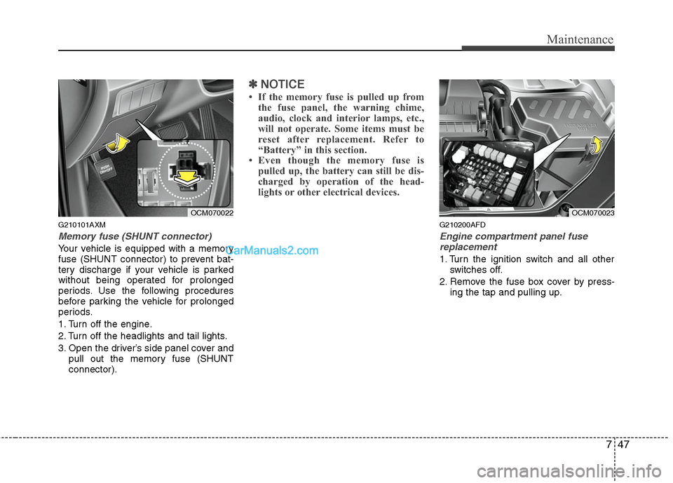
G210101AXM
Memory fuse (SHUNT connector)
Your vehicle is equipped with a memory
fuse (SHUNT connector) to prevent bat-
tery discharge if your vehicle is parked
without being operated for prolonged
periods. Use the following procedures
before parking the vehicle for prolonged
periods.
1. Turn off the engine.
2. Turn off the headlights and tail lights.
3. Open the driver’s side panel cover andpull out the memory fuse (SHUNT
connector).
✽ ✽NOTICE
• If the memory fuse is pulled up from
the fuse panel, the warning chime,
audio, clock and interior lamps, etc.,
will not operate. Some items must be
reset after replacement. Refer to
“Battery” in this section.
• Even though the memory fuse is pulled up, the battery can still be dis-
charged by operation of the head-
lights or other electrical devices.
G210200AFD
Engine compartment panel fuse
replacement
1. Turn the ignition switch and all other switches off.
2. Remove the fuse box cover by press- ing the tap and pulling up.
OCM070022
OCM070023
Page 367 of 408
Maintenance
48
7
3. Check the removed fuse; replace it if it
is blown. To remove or insert the fuse,
use the fuse puller in the engine com-
partment fuse panel.
4. Push in a new fuse of the same rating, and make sure it fits tightly in the clips.
If it fits loosely, consult an authorized
HYUNDAI dealer.
G210201ACM
Main fuse
If the main fuse is blown, it must be
removed as follows:
1. Disconnect the negative battery cable.
2. Remove the bolts shown in the pictureabove.
3. Replace the fuse with a new one of the same rating.
4. Reinstall in the reverse order of removal.
✽ ✽NOTICE
If the main fuse is blown, consult an
Authorized HYUNDAI Dealer.
CAUTION
After checking the fuse box in the
engine compartment, securelyinstall the fuse box cover. If not,electrical failures may occur from water leaking in.
OCM070025
Page 368 of 408
749
Maintenance
✽
✽NOTICE
Not all fuse panel descriptions in this
manual may be applicable to your vehi-
cle. It is accurate at the time of printing.
When you inspect the fuse box on your
vehicle, refer to the fuse box label.
Engine compartment
OCM070026/OCM070027
G210300AFD
Fuse/Relay panel description
Inside the fuse/relay box covers, you can find the fuse/relay label describing fuse/relay
name and capacity.
Driver’s side panel
Page 369 of 408

Maintenance
50
7
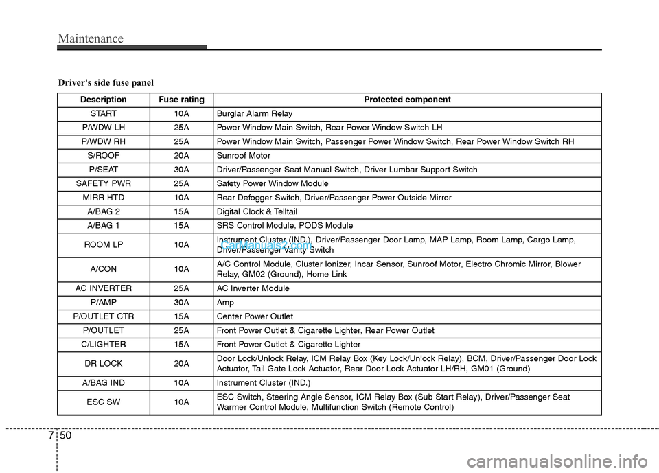
Driver's side fuse panel
Description Fuse rating Protected component
START 10A Burglar Alarm Relay
P/WDW LH 25A Power Window Main Switch, Rear Power Window Switch LH
P/WDW RH 25A Power Window Main Switch, Passenger Power Window Switch, Rear Power Window Switch RH S/ROOF 20A Sunroof MotorP/SEAT 30A Driver/Passenger Seat Manual Switch, Driver Lumbar Support Switch
SAFETY PWR 25A Safety Power Window Module MIRR HTD 10A Rear Defogger Switch, Driver/Passenger Power Outside MirrorA/BAG 2 15A Digital Clock & Telltail
A/BAG 1 15A SRS Control Module, PODS Module
ROOM LP 10A Instrument Cluster (IND.), Driver/Passenger Door Lamp, MAP Lamp, Room Lamp, Cargo Lamp,
Driver/Passenger Vanity Switch
A/CON 10A A/C Control Module, Cluster Ionizer, Incar Sensor, Sunroof Motor, Electro Chromic Mirror, Blower
Relay, GM02 (Ground), Home Link
AC INVERTER 25A AC Inverter Module P/AMP 30A Amp
P/OUTLET CTR 15A Center Power Outlet P/OUTLET 25A Front Power Outlet & Cigarette Lighter, Rear Power Outlet
C/LIGHTER 15A Front Power Outlet & Cigarette Lighter
DR LOCK 20A Door Lock/Unlock Relay, ICM Relay Box (Key Lock/Unlock Relay), BCM, Driver/Passenger Door Lock
Actuator, Tail Gate Lock Actuator, Rear Door Lock Actuator LH/RH, GM01 (Ground)
A/BAG IND 10A Instrument Cluster (IND.)
ESC SW10AESC Switch, Steering Angle Sensor, ICM Relay Box (Sub Start Relay), Driver/Passenger Seat
Warmer Control Module, Multifunction Switch (Remote Control)