Page 436 of 560
Features of your vehicle
24
4
Opening the bonnet
1. Pull the release lever to unlatch the
bonnet. The bonnet should pop open
slightly. 2. Go to the front of the vehicle, raise the
bonnet slightly, pull the secondarylatch (1) inside of the bonnet centreand lift the bonnet (2). 3. Pull out the support rod.
4. Hold the bonnet opened with the sup-
port rod.
BONNET
OLM049025ROLM049026OLM049027
WARNING
- Hot parts
Grasp the support rod in the area
wrapped in rubber. The plastic will
help prevent you from being burned
by hot metal when the engine ishot.
EL UK 4A.QXP 1/25/2010 9:44 AM Page 24
Page 437 of 560

425
Features of your vehicle
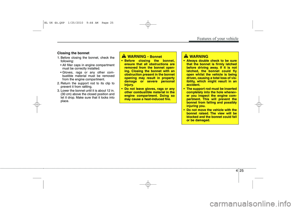
Closing the bonnet
1. Before closing the bonnet, check thefollowing:
All filler caps in engine compartment must be correctly installed.
Gloves, rags or any other com- bustible material must be removed
from the engine compartment.
2. Return the support rod to its clip to prevent it from rattling.
3. Lower the bonnet until it is about 12 in. (30 cm) above the closed position and
let it drop. Make sure that it locks into
place.
WARNING - Bonnet
Before closing the bonnet, ensure that all obstructions are
removed from the bonnet open-
ing. Closing the bonnet with anobstruction present in the bonnet
opening may result in property
damage or severe personal
injury.
Do not leave gloves, rags or any other combustible material in the
engine compartment. Doing so
may cause a heat-induced fire.WARNING
Always double check to be sure that the bonnet is firmly latched
before driving away. If it is not
latched, the bonnet could fly
open whilst the vehicle is being
driven, causing a total loss of vis-
ibility, which might result in anaccident.
The support rod must be inserted completely into the hole whenev-
er you inspect the engine com-
partment. This will prevent the
bonnet from falling and possibly
injuring you.
Do not move the vehicle with the bonnet raised. The view will be
blocked and the bonnet could fall
or be damaged.
EL UK 4A.QXP 1/25/2010 9:44 AM Page 25
Page 438 of 560

Features of your vehicle
26
4
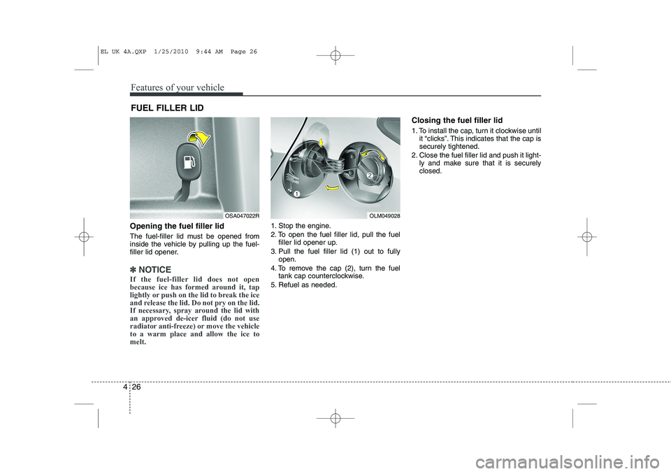
Opening the fuel filler lid
The fuel-filler lid must be opened from
inside the vehicle by pulling up the fuel-
filler lid opener.
✽✽
NOTICE
If the fuel-filler lid does not open
because ice has formed around it, tap
lightly or push on the lid to break the ice
and release the lid. Do not pry on the lid.
If necessary, spray around the lid with
an approved de-icer fluid (do not use
radiator anti-freeze) or move the vehicleto a warm place and allow the ice tomelt.
1. Stop the engine.
2. To open the fuel filler lid, pull the fuel filler lid opener up.
3. Pull the fuel filler lid (1) out to fully open.
4. To remove the cap (2), turn the fuel tank cap counterclockwise.
5. Refuel as needed. Closing the fuel filler lid
1. To install the cap, turn it clockwise until
it “clicks”. This indicates that the cap is securely tightened.
2. Close the fuel filler lid and push it light- ly and make sure that it is securelyclosed.
FUEL FILLER LID
OSA047022ROLM049028
EL UK 4A.QXP 1/25/2010 9:44 AM Page 26
Page 440 of 560

Features of your vehicle
28
4
(Continued)
Use only portable plastic fuel
containers designed to carry and
store petrol.
Do not use mobile phones whilst refuelling. Electric current and/or
electronic interference from
mobile phones can potentially
ignite fuel vapours causing a fire.
When refuelling, always shut the engine off. Sparks produced byelectrical components related tothe engine can ignite fuel
vapours causing a fire. Once
refuelling is complete, check tomake sure the filler cap and filler
door are securely closed, before
starting the engine.
DO NOT use matches or a lighter and DO NOT SMOKE or leave a lit
cigarette in your vehicle whilst at
a gas station especially during
refuelling. Automotive fuel is
highly flammable and can, when
ignited, result in fire.
(Continued)(Continued)
If a fire breaks out during refu-elling, leave the vicinity of the
vehicle, and immediately contact
the manager of the gas stationand then contact the local fire
department. Follow any safety
instructions they provide.CAUTION
Make sure to refuel your vehicle
according to the "Fuel require-
ments" suggested in section 1.
If the fuel filler cap requires replacement, use only a genuineHYUNDAI cap or the equivalent
specified for your vehicle. Anincorrect fuel filler cap can result in a serious malfunction of thefuel system or emission control
system.
Do not spill fuel on the exterior surfaces of the vehicle. Any typeof fuel spilled on painted surfaces
may damage the paint.
After refuelling, make sure the fuel cap is installed securely toprevent fuel spillage in the eventof an accident.
EL UK 4A.QXP 1/25/2010 9:44 AM Page 28
Page 445 of 560
433
Features of your vehicle
Electric power steering (if equipped)
Power steering uses the motor to assist
you in steering the vehicle. If the engine
is off or if the power steering system
becomes inoperative, the vehicle may
still be steered, but it will require
increased steering effort.
The motor driven power steering is con-
trolled by the power steering control unit
which senses the steering wheel torque
and vehicle speed to command the
motor.
The steering wheel becomes heavier as
the vehicle’s speed increases and
becomes lighter as the vehicle’s speed
decreases for better control of the steer-ing wheel.
Should you notice any change in the
effort required to steer during normal
vehicle operation, have the power steer-
ing checked by a HYUNDAI authorised
repairer.✽✽NOTICE
The following symptoms may occur dur- ing normal vehicle operation:
Page 447 of 560

435
Features of your vehicle
Inside rearview mirror
Adjust the rearview mirror to centre on
the view through the rear window. Make
this adjustment before you start driving.
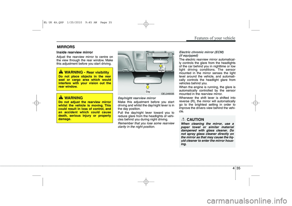
Day/night rearview mirror
Make this adjustment before you start
driving and whilst the day/night lever is in
the day position.
Pull the day/night lever toward you to
reduce glare from the headlights of vehi-
cles behind you during night driving.
Remember that you lose some rearviewclarity in the night position.
Electric chromic mirror (ECM) (if equipped)
The electric rearview mirror automatical- ly controls the glare from the headlights
of the car behind you in nighttime or low
light driving conditions. The sensormounted in the mirror senses the light
level around the vehicle, and automati-cally controls the headlight glare from
vehicles behind you.
When the engine is running, the glare is
automatically controlled by the sensor
mounted in the rearview mirror.
Whenever the shift lever is shifted into
reverse (R), the mirror will automatically
go to the brightest setting in order to
improve the drivers view behind the vehi-
cle.
MIRRORS
WARNING -
Rear visibility
Do not place objects in the rear
seat or cargo area which would
interfere with your vision out the
rear window.
OEL049035
CAUTION
When cleaning the mirror, use a paper towel or similar materialdampened with glass cleaner. Do not spray glass cleaner directly on
the mirror as that may cause the liq- uid cleaner to enter the mirror hous-ing.
Day
Night
WARNING
Do not adjust the rearview mirror
whilst the vehicle is moving. This
could result in loss of control, and
an accident which could cause
death, serious injury or property
damage.
EL UK 4A.QXP 1/25/2010 9:45 AM Page 35
Page 453 of 560
441
Features of your vehicle
Electric type (if equipped)
To fold the outside rearview mirror,
depress the button.
To unfold it, depress the button again.
OLM049041R
CAUTION
In case it is an electric type outsiderearview mirror, don’t fold it by
hand. It could cause motor failure.
CAUTION
The electric type outside rearviewmirror operates even though the ignition switch is in the OFF posi-
tion. However, to prevent unneces-sary battery discharge, do not adjust the mirrors longer than nec-essary whilst the engine is not run-
ning.
EL UK 4A.QXP 1/25/2010 9:46 AM Page 41
Page 454 of 560
Features of your vehicle
42
4
INSTRUMENT CLUSTER
1. Tachometer
2. Speedometer
3. Engine temperature gauge
4. Fuel gauge
5. Warning and indicator lights (if equipped)
6. Turn signal indicators
7. Odometer/Trip computer (if equipped)
OEL049304U/OEL049300U
* The actual cluster in the vehicle may differ
from the illustration.
For more details refer to the "Gauges" in
the next pages.
■■ Type A
■■Type B
EL UK 4A.QXP 1/25/2010 9:46 AM Page 42