2011 Hyundai H-100 Truck hood release
[x] Cancel search: hood releasePage 9 of 211
F9
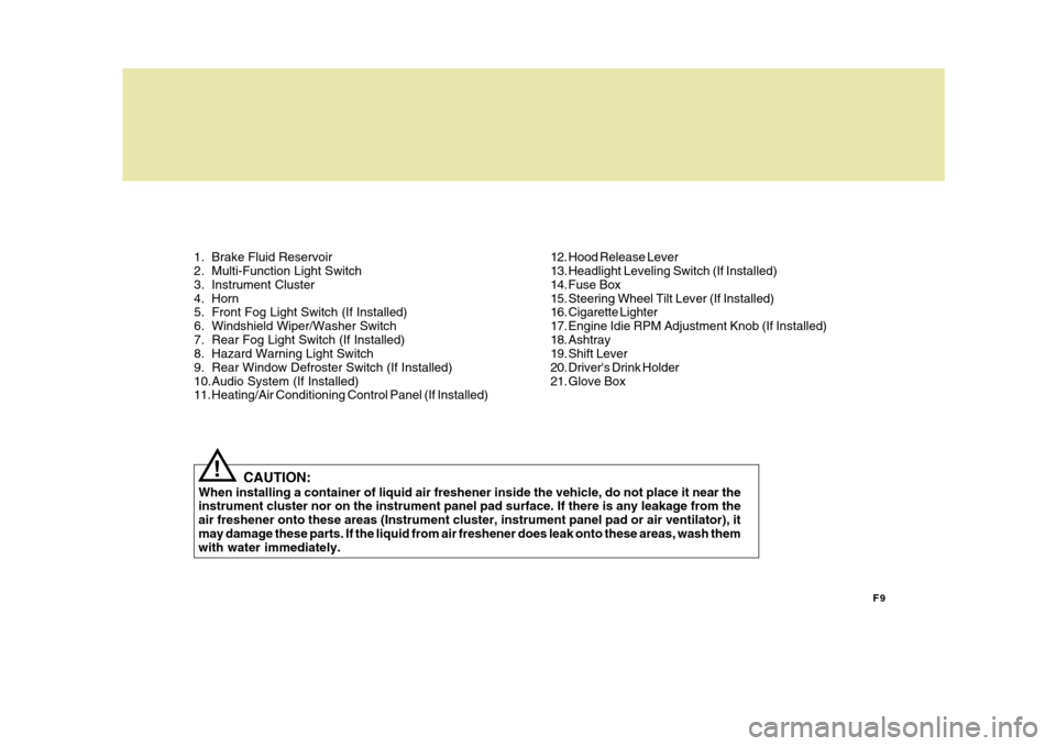
1. Brake Fluid Reservoir
2. Multi-Function Light Switch
3. Instrument Cluster
4. Horn
5. Front Fog Light Switch (If Installed)
6. Windshield Wiper/Washer Switch
7. Rear Fog Light Switch (If Installed)
8. Hazard Warning Light Switch
9. Rear Window Defroster Switch (If Installed)
10.Audio System (If Installed)
11. Heating/Air Conditioning Control Panel (If Installed)
CAUTION:
When installing a container of liquid air freshener inside the vehicle, do not place it near theinstrument cluster nor on the instrument panel pad surface. If there is any leakage from the air freshener onto these areas (Instrument cluster, instrument panel pad or air ventilator), itmay damage these parts. If the liquid from air freshener does leak onto these areas, wash them with water immediately.
! 12. Hood Release Lever
13. Headlight Leveling Switch (If Installed)
14. Fuse Box
15. Steering Wheel Tilt Lever (If Installed)
16. Cigarette Lighter
17. Engine Idie RPM Adjustment Knob (If Installed)
18. Ashtray
19. Shift Lever
20. Driver's Drink Holder
21. Glove Box
Page 11 of 211
F11
CAUTION:
When installing a container of liquid air freshener inside the vehicle, do not place it near the instrument cluster nor on the instrument panel pad surface. If there is any leakage from the air freshener onto these areas (Instrument cluster, instrument panel pad or air ventilator), it may damage these parts. If the liquid from air freshener does leak onto these areas, wash themwith water immediately.
!
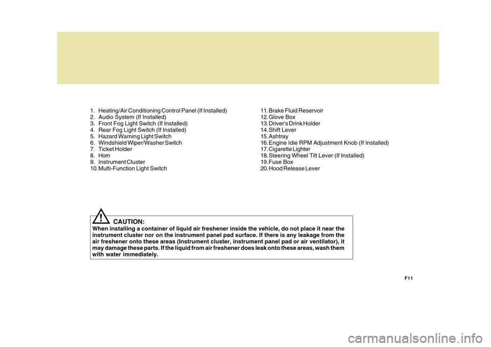
1. Heating/Air Conditioning Control Panel (If Installed)
2. Audio System (If Installed)
3. Front Fog Light Switch (If Installed)
4. Rear Fog Light Switch (If Installed)
5. Hazard Warning Light Switch
6. Windshield Wiper/Washer Switch
7. Ticket Holder
8. Horn
9. Instrument Cluster
10. Multi-Function Light Switch
11. Brake Fluid Reservoir
12. Glove Box
13. Driver's Drink Holder
14. Shift Lever
15. Ashtray
16. Engine Idie RPM Adjustment Knob (If Installed)
17. Cigarette Lighter
18. Steering Wheel Tilt Lever (If Installed)
19. Fuse Box
20. Hood Release Lever
Page 39 of 211
1
FEATURES OF YOUR HYUNDAI
27
! B260J01S-GAT
Charging System Warning Light
The charging system warning light should come on when the ignition isturned on, then go out when the engine is running. If the light stays on while the engine is running, there is a malfunc-tion in the electrical charging system. If the light comes on while you are driv- ing, stop, turn off the engine and checkunder the hood. First, make certain the generator drive belt is in place. If it is, check the tension of the belt.And then, have the system checked by your Hyundai dealer.
CAUTION:
If the drive belt (generator belt) is loosen, broken, or mission while the vehicle is driving, there may be a serious malfunction, engine couldoverheat because this belt also drives the water pump.!
time, you should slow the vehicle and bring it to a complete stop in a safelocation off the roadway. The brake fluid level warning light indi- cates that the brake fluid level in thebrake master cylinder is low and hy- draulic brake fluid conforming to DOT 3 or DOT 4 specifications should be added.After adding fluid, if no other trouble is found, the car should be immediately and carefully driven to a Hyundai dealerfor inspection. If further trouble is expe- rienced, the vehicle should not be driven at all but taken to a dealer by a profes-sional towing service or some other safe method. Your Hyundai is equipped with dual-diagonal braking systems. This means you still have braking on two wheels even if one of the dual systems shouldfail. With only one of the dual systems working, more than normal pedal travel and greater pedal pressure are requiredto stop the car. Also, the car will not stop in as short a distance with only half of the brake system working. If thebrakes fail while you are driving, shift to a lower gear for additional engine brak- ing and stop the car as soon as it is safeto do so. CAUTION:
The parking brake/low brake fluid warning light should also come on when the vacuum level in brakebooster descends to about 275 mmHg or below. The brake system is de- signed to stop the vehicle with re-serve assist if brake pedal is held down. This reserve is greatly reduced each time you release the brake.Without vacuum assist your vehicle can still be stopped by pushing much harder on brake pedal, however thestopping distance may be much longer. If the light comes on at any other time, you should slow the ve-hicle and bring it to a complete stop in a safe location off the roadway. After starting the engine, do not drivethe vehicle until the vacuum level is above 275 mmHg below atmosphere and warning light has turned off. Iffurther trouble is experienced, the vehicle should not be driven at all but taken to a dealer by a profes-sional towing service.
Page 59 of 211
1
FEATURES OF YOUR HYUNDAI
47
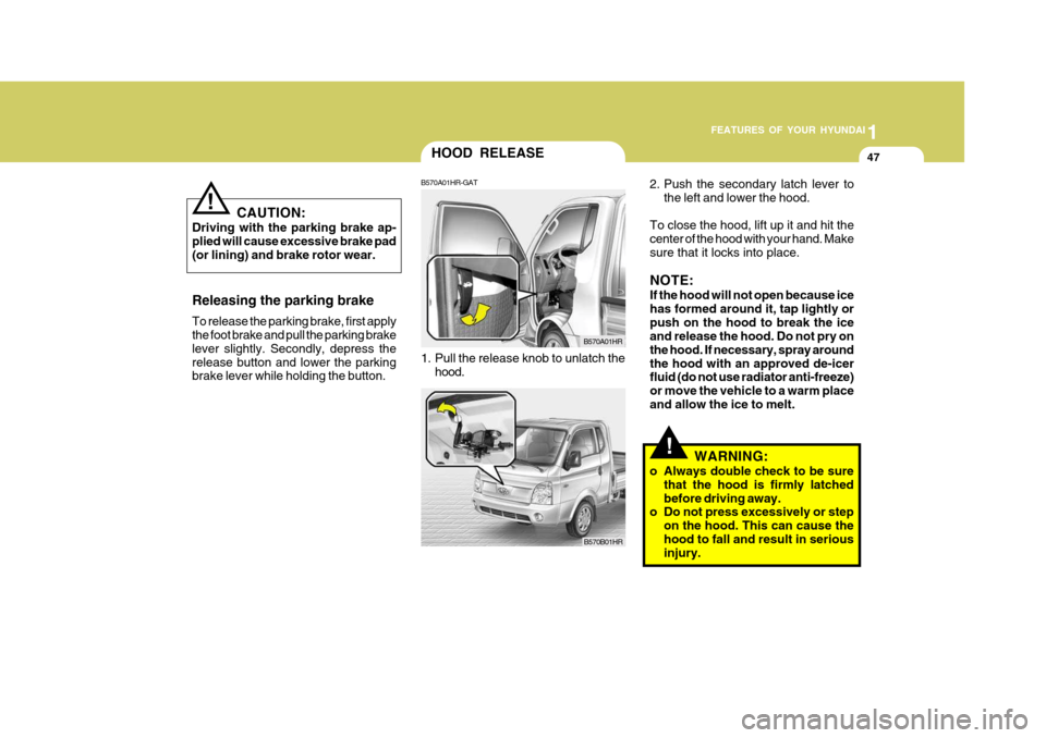
2. Push the secondary latch lever to the left and lower the hood.
To close the hood, lift up it and hit the center of the hood with your hand. Makesure that it locks into place. NOTE: If the hood will not open because ice has formed around it, tap lightly orpush on the hood to break the ice and release the hood. Do not pry on the hood. If necessary, spray aroundthe hood with an approved de-icer fluid (do not use radiator anti-freeze) or move the vehicle to a warm placeand allow the ice to melt.
!WARNING:
o Always double check to be sure that the hood is firmly latched before driving away.
o Do not press excessively or step
on the hood. This can cause thehood to fall and result in serious injury.
HOOD RELEASE
B570A01HR-GAT
1. Pull the release knob to unlatch the hood.
B570B01HR
B570A01HR
Releasing the parking brake To release the parking brake, first apply the foot brake and pull the parking brake lever slightly. Secondly, depress therelease button and lower the parking brake lever while holding the button. CAUTION:
Driving with the parking brake ap- plied will cause excessive brake pad(or lining) and brake rotor wear.
!
Page 209 of 211
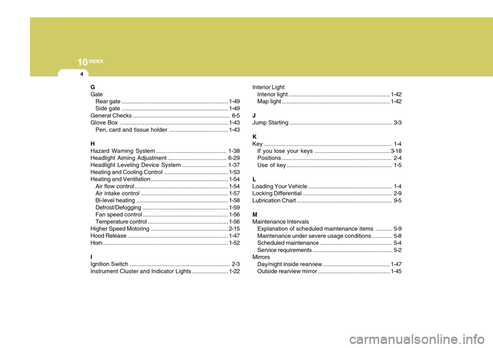
10INDEX
4
G GateRear gate ................................................................. 1-49
Side gate ................................................................. 1-49
General Checks ........................................................... 6-5
Glove Box .................................................................. 1-43
Pen, card and tissue holder ....................................1-43
HHazard Warning Syst em ........................................... 1-38
Headlight Aiming Adjustment ....................................6-29
Headlight Leveling Device Syst em ...........................1-37
Heating and Cooling Control .......................................1-53
Heating and Ventilation ............................................... 1-54
Air flow control ......................................................... 1-54
Air intake control ..................................................... 1-57
Bi-level heating ........................................................ 1-58
Defrost/Defogging .................................................... 1-59
Fan speed control .................................................... 1-56
Temperature control ................................................. 1-56
Higher Speed Motoring ............................................... 2-15
Hood Release ............................................................. 1-47
Horn ............................................................................ 1-52
IIgnition Switch ............................................................. 2-3
Instrument Cluster and Indicator Lights ...................... 1-22Interior Light
Interior light .............................................................. 1-42
Map light .................................................................. 1-42
JJump Starting .............................................................. 3-3
K
Key .............................................................................. 1-4 If you lose your keys .............................................. 3-18
Positions ................................................................... 2-4
Use of key ................................................................ 1-5
L Loading Your Vehicle ................................................... 1-4
Locking Differential ...................................................... 2-9
Lubrication Chart .......................................................... 9-5
M Maintenance Intervals Explanation of scheduled maintenance items .......... 5-9Maintenance under severe usage conditions ............ 5-8
Scheduled maintenance ............................................ 5-4
Service requirements ................................................ 5-2
Mirrors Day/night inside rearview .................. .......................1-47
Outside rearview mirror............................................ 1-45