2011 Hyundai H-100 Truck lights
[x] Cancel search: lightsPage 118 of 211
3
WHAT TO DO IN AN EMERGENCY
3
!
JUMP STARTING
WARNING:
The gas produced by the battery during the jump-start operation ishighly explosive. If these instruc- tions are not followed exactly, seri- ous personal injury and damage tothe vehicle may occur! If you are not sure how to follow this proce- dure, seek qualified assistance.Automobile batteries contain sul- furic acid. This is poisonous and highly corrosive. When jump start-ing, wear protective glasses and be careful not to get acid on yourself, your clothing or on the car. 3. Attach the clamps of the jumper
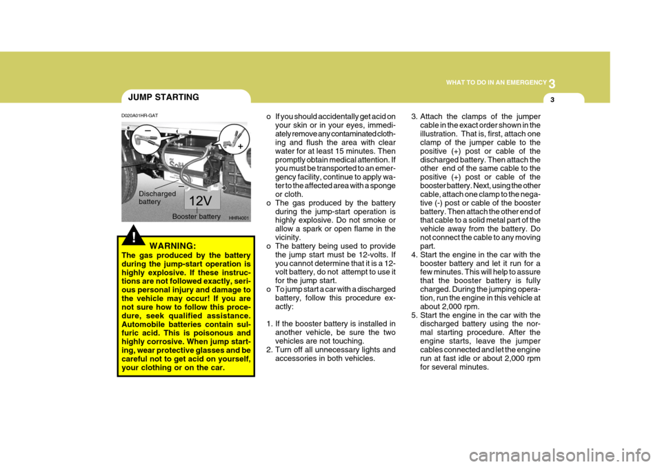
cable in the exact order shown in theillustration. That is, first, attach one clamp of the jumper cable to the positive (+) post or cable of thedischarged battery. Then attach the other end of the same cable to the positive (+) post or cable of thebooster battery. Next, using the other cable, attach one clamp to the nega- tive (-) post or cable of the boosterbattery. Then attach the other end of that cable to a solid metal part of the vehicle away from the battery. Donot connect the cable to any moving part.
4. Start the engine in the car with the booster battery and let it run for afew minutes. This will help to assure that the booster battery is fullycharged. During the jumping opera- tion, run the engine in this vehicle at about 2,000 rpm.
5. Start the engine in the car with the discharged battery using the nor-mal starting procedure. After theengine starts, leave the jumper cables connected and let the engine run at fast idle or about 2,000 rpmfor several minutes.
D020A01HR-GAT
o If you should accidentally get acid on
your skin or in your eyes, immedi-ately remove any contaminated cloth- ing and flush the area with clear water for at least 15 minutes. Thenpromptly obtain medical attention. If you must be transported to an emer- gency facility, continue to apply wa-ter to the affected area with a sponge or cloth.
o The gas produced by the battery during the jump-start operation ishighly explosive. Do not smoke or allow a spark or open flame in thevicinity.
o The battery being used to provide
the jump start must be 12-volts. Ifyou cannot determine that it is a 12- volt battery, do not attempt to use it for the jump start.
o To jump start a car with a discharged battery, follow this procedure ex-actly:
1. If the booster battery is installed in another vehicle, be sure the twovehicles are not touching.
2. Turn off all unnecessary lights and
accessories in both vehicles.
Discharged battery
Booster batteryHHR4001
Page 119 of 211
3 WHAT TO DO IN AN EMERGENCY
4
!
IF THE ENGINE OVERHEATS
D030A01HR-GAT If your temperature gauge indicates overheating, you experience a loss of power, or hear loud pinging or knock- ing, the engine is probably too hot. Ifthis happens to you, you should:
1. Pull off the road and stop as soon as it is safe to do so.
2. Place the gear selector lever in neu-
tral and set the parking brake. If the air conditioning is on, turn it off.
3. If engine coolant is running out un-
der the car or steam is coming outfrom the hood, allow the engine to idle. Do not open the hood until the engine coolant has stopped runningor the steaming has stopped. If there is no visible loss of engine coolant and no steam, leave the enginerunning, lift up the passenger's seat
(Refer to "To Inspect the Engine
Compartment Under the Passenger's
Seat" on page 1-13.) and check to be sure the engine cooling fan is oper- ating. If the fan is not running, turnthe engine off.
6. Carefully remove the jumper cables
in the reverse order of attachment.
If you do not know why your batterybecame discharged (because the lightswere left on, etc.), have the charging system checked by your Hyundai dealer. 4. Check to see if the water pump drive
belt is missing. If it is not missing,check to see that it is tight. If the drive belt seems to be satisfactory, check for coolant leaking from theradiator, hoses or under the car. (If the air conditioning had been in use, it is normal for cold water to bedraining from it when you stop).
WARNING:
While the engine is running, keephair, hands, and clothing away from moving parts such as the fan and drive belts to prevent injury.
HHR4002
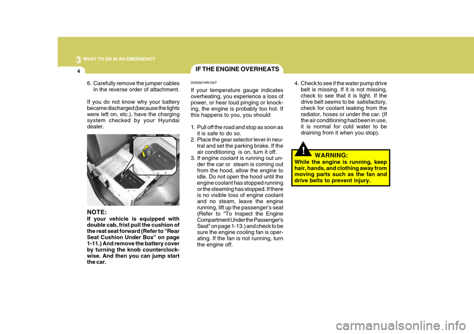
NOTE: If your vehicle is equipped with double cab, frist pull the cushion of the reat seat forward (Refer to "RearSeat Cushion Under Box" on page 1-11.) And remove the battery cover by turning the knob counterclock-wise. And then you can jump start the car.
Page 156 of 211
6
DO-IT-YOURSELF MAINTENANCE
5
G020A01HR-GAT Engine Compartment The following should be checked regu- larly:
o Engine oil level and condition
o Transmission fluid level and condi-
tion
o Brake fluid level
o Engine coolant level
o Windshield washer fluid level
o Accessory drive belt condition
o Engine coolant hose condition
o Fluid leaks (on or below compo- nents)
o Power steering fluid level
o Battery condition
o Air filter condition G020C01HR-GAT Vehicle Interior The following should be checked each time when the vehicle is driven:
o Lights operation
o Windshield wiper operation
o Horn operation
o Defroster, heater system operation
(and air conditioning, if installed)
o Steering operation and condition
o Mirror condition and operation
o Turn signal operation
o Accelerator pedal operation
o Brake operation, including parking
brake
o Manual transmission operation, in- cluding clutch operation
o Seat control condition and operation
o Seat belt condition and operation
o Sunvisor operation If you notice anything that does not operate correctly or appears to be functioning incorrectly, inspect it care-fully and seek assistance from your Hyundai dealer if service is needed.
G020B01A-AAT Vehicle Exterior The following should be checked monthly:
o Overall appearance and condition
o Wheel condition and wheel nut torque
o Exhaust system condition
o Light condition and operation
o Windshield glass condition
o Wiper blade condition
o Paint condition and body corrosion
o Fluid leaks
o Door and hood lock condition
o Tire pressure and condition
(including spare tire)
GENERAL CHECKS
Page 173 of 211
6 DO-IT-YOURSELF MAINTENANCE
22
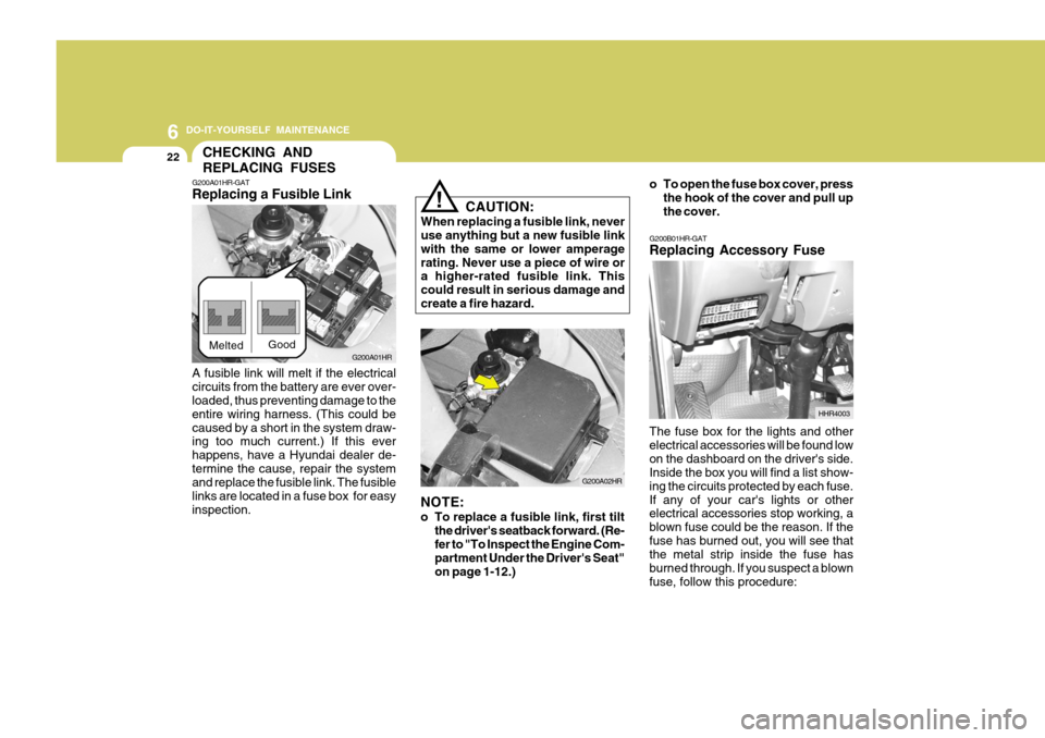
G200B01HR-GAT Replacing Accessory Fuse The fuse box for the lights and other electrical accessories will be found lowon the dashboard on the driver's side. Inside the box you will find a list show- ing the circuits protected by each fuse.If any of your car's lights or other electrical accessories stop working, a blown fuse could be the reason. If thefuse has burned out, you will see that the metal strip inside the fuse has burned through. If you suspect a blownfuse, follow this procedure: HHR4003
CHECKING AND REPLACING FUSES
CAUTION:
When replacing a fusible link, never use anything but a new fusible link with the same or lower amperagerating. Never use a piece of wire or a higher-rated fusible link. This could result in serious damage andcreate a fire hazard.
!
G200A01HR-GAT Replacing a Fusible Link
G200A01HR
Melted
Good
A fusible link will melt if the electrical circuits from the battery are ever over- loaded, thus preventing damage to the entire wiring harness. (This could becaused by a short in the system draw- ing too much current.) If this ever happens, have a Hyundai dealer de-termine the cause, repair the system and replace the fusible link. The fusible links are located in a fuse box for easyinspection. NOTE:
o To replace a fusible link, first tilt
the driver's seatback forward. (Re- fer to "To Inspect the Engine Com- partment Under the Driver's Seat" on page 1-12.) G200A02HRo To open the fuse box cover, press
the hook of the cover and pull upthe cover.
Page 175 of 211
6 DO-IT-YOURSELF MAINTENANCE
24
!
CHECKING THE BATTERY
G210A01A-AAT
WARNING:
Batteries can be dangerous! When working with batteries, carefully ob-serve the following precautions to avoid serious injuries. D010B01HR
The fluid in the battery contains a strong solution of sulfuric acid, which is poi- sonous and highly corrosive. Be careful not to spill it on yourself or the car. If youdo spill battery fluid on yourself, imme- diately do the following:
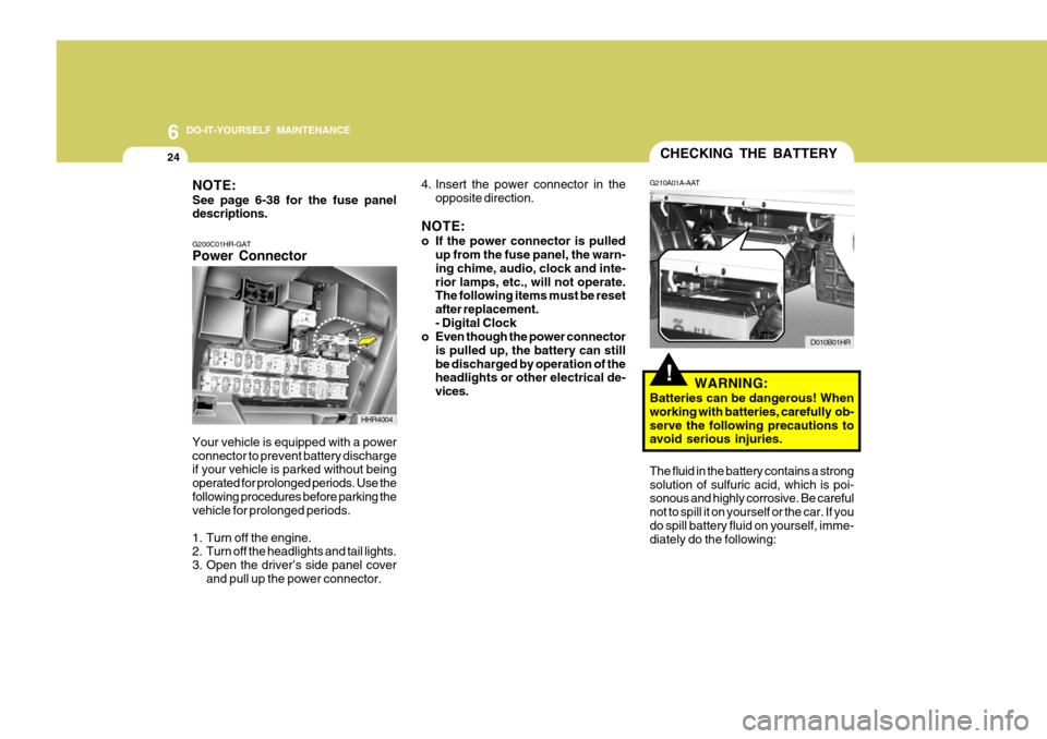
NOTE: See page 6-38 for the fuse panel descriptions. G200C01HR-GAT Power Connector
4. Insert the power connector in the
opposite direction.
NOTE:
o If the power connector is pulled up from the fuse panel, the warn- ing chime, audio, clock and inte-rior lamps, etc., will not operate. The following items must be reset after replacement.- Digital Clock
o Even though the power connector
is pulled up, the battery can stillbe discharged by operation of the headlights or other electrical de- vices.
Your vehicle is equipped with a powerconnector to prevent battery discharge if your vehicle is parked without being operated for prolonged periods. Use thefollowing procedures before parking the vehicle for prolonged periods.
1. Turn off the engine.
2. Turn off the headlights and tail lights.
3. Open the driver’s side panel cover and pull up the power connector.
HHR4004
Page 180 of 211
6
DO-IT-YOURSELF MAINTENANCE
29
!WARNING:
o Do not smoke or have any other open flame near the vehicle while bleeding the fuel system.
o Be sure to carefully wipe away any
water drained out in this manner,because the fuel mixed in the wa- ter might be ignited and result in a fire.
HEADLIGHT AIMING ADJUSTMENT
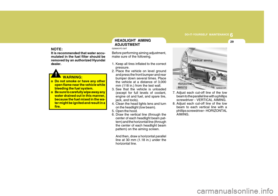
7. Adjust each cut-off line of the lowbeam to the parallel line with a phillips screwdriver - VERTICAL AIMING.
8. Adjust each cut-off line of the low beam to each vertical line with a phillips screwdriver - HORIZONTALAIMING. G290A01HR
Horizontal aiming
Vertical aiming
G290A01FC-GAT Before performing aiming adjustment, make sure of the following.
1. Keep all tires inflated to the correct
pressure.
2. Place the vehicle on level ground
and press the front bumper and rear bumper down several times. Place the vehicle at a distance of 3,000 mm (118 in.) from the test wall.
3. See that the vehicle is unloaded (except for full levels of coolant,engine oil and fuel, and spare tire,jack, and tools).
4. Clean the head lights lens and turn
on the headlight (low beam).
5. Open the hood.
6. Draw the vertical line (through the
center of each headlight beam pat- tern) and the horizontal line (through the center of each headlight beam pattern) on the aiming screen. And then, draw a horizontal parallel line at 30 mm (1.18 in.) under thehorizontal line.
NOTE: It is recommended that water accu- mulated in the fuel filter should be removed by an authorized Hyundaidealer.
Page 181 of 211
6 DO-IT-YOURSELF MAINTENANCE
30REPLACEMENT OF LIGHT BULBS
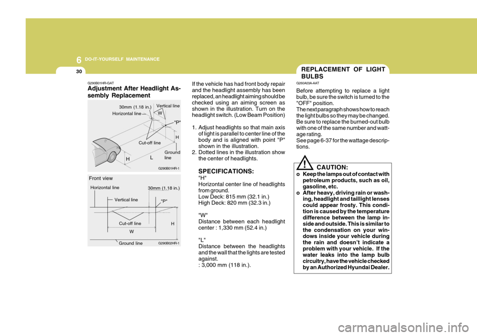
If the vehicle has had front body repair and the headlight assembly has been replaced, an headlight aiming should be checked using an aiming screen asshown in the illustration. Turn on the headlight switch. (Low Beam Position)
1. Adjust headlights so that main axis of light is parallel to center line of the body and is aligned with point "P"shown in the illustration.
2. Dotted lines in the illustration show
the center of headlights. SPECIFICATIONS: "H" Horizontal center line of headlights from ground.Low Deck: 815 mm (32.1 in.) High Deck: 820 mm (32.3 in.) "W" Distance between each headlight center : 1,330 mm (52.4 in.) "L" Distance between the headlightsand the wall that the lights are tested against. : 3,000 mm (118 in.). G260A03A-AAT Before attempting to replace a light bulb, be sure the switch is turned to the "OFF" position. The next paragraph shows how to reachthe light bulbs so they may be changed. Be sure to replace the burned-out bulb with one of the same number and watt-age rating. See page 6-37 for the wattage descrip- tions.
CAUTION:
o Keep the lamps out of contact with petroleum products, such as oil,gasoline, etc.
o After heavy, driving rain or wash- ing, headlight and taillight lensescould appear frosty. This condi-tion is caused by the temperature difference between the lamp in- side and outside. This is similar tothe condensation on your win- dows inside your vehicle during the rain and doesn’t indicate aproblem with your vehicle. If the water leaks into the lamp bulb circuitry, have the vehicle checkedby an Authorized Hyundai Dealer.
!
G290B01HR-GAT Adjustment After Headlight As- sembly Replacement
G290B01HR-1
H
Ground line
30mm (1.18 in.)
Vertical line
L
Cut-off line "P"
Horizontal line
G290B02HR-1
30mm (1.18 in.)
Front view
Horizontal line
Vertical line
Cut-off lineH
W H
W
Ground line
"P"
Page 188 of 211
6
DO-IT-YOURSELF MAINTENANCE
37BULB WATTAGES
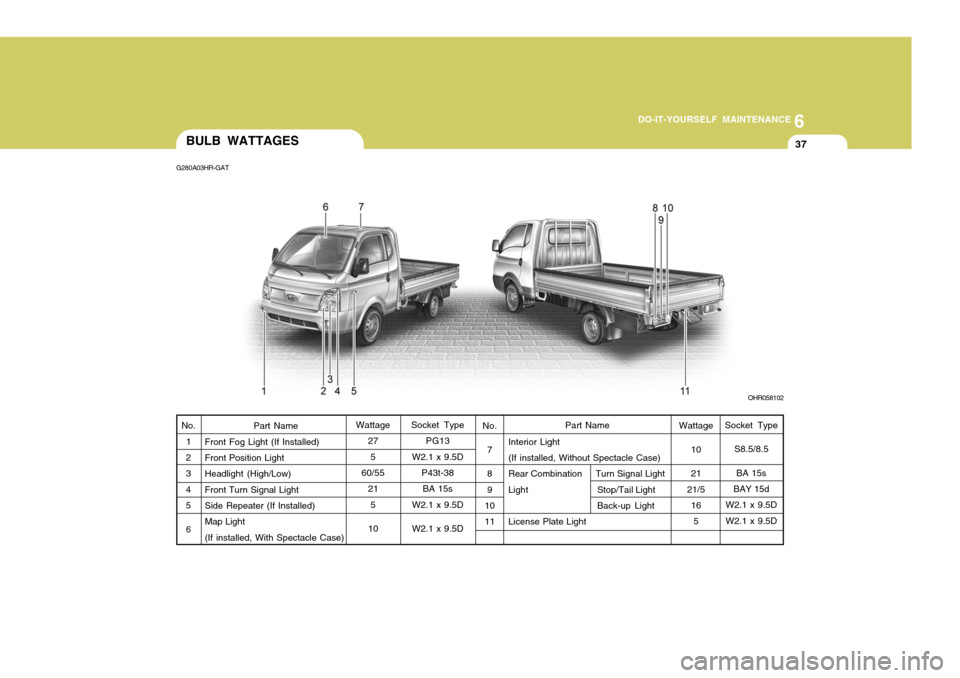
Interior Light (If installed, Without Spectacle Case) Rear Combination Turn Signal Light
Light Stop/Tail LightBack-up Light
License Plate Light
Part Name
Front Fog Light (If Installed)Front Position Light Headlight (High/Low) Front Turn Signal LightSide Repeater (If Installed) Map Light (If installed, With Spectacle Case) No.
7 8 9
10 11
G280A03HR-GAT
OHR058102
Wattage 27
5
60/55 21
5
10
No. 1
2 3 45 6Wattage
10 21
21/5
165
Part NameSocket Type
PG13
W2.1 x 9.5D P43t-38BA 15s
W2.1 x 9.5D W2.1 x 9.5D Socket Type
S8.5/8.5BA 15s
BAY 15d
W2.1 x 9.5D W2.1 x 9.5D