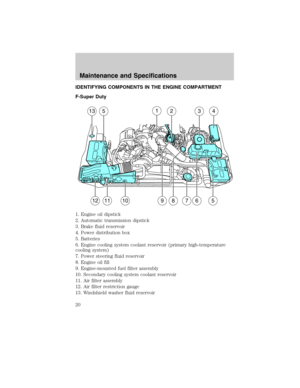
Page 49 of 90

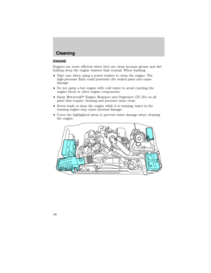
AIR FILTER RESTRICTION GAUGE AND AIR FILTER
REPLACEMENT
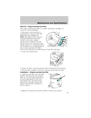
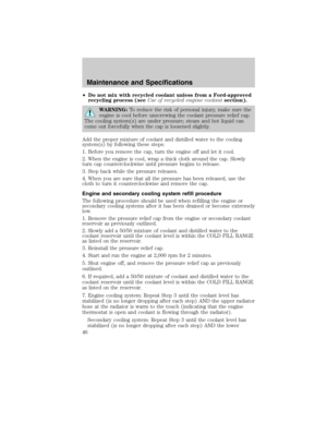
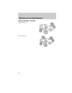
Air filter restriction gauge:
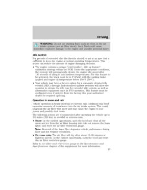
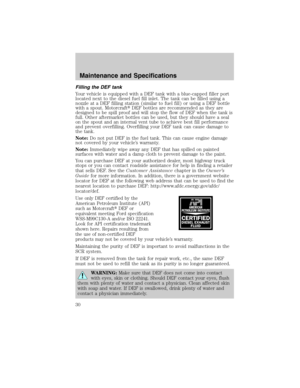
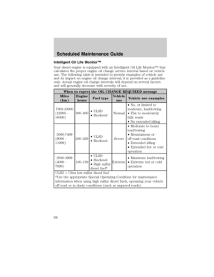
The restriction gauge, located on
the upper housing of the air filter
assembly, measures the vacuum
inside the air filter. The more the air
filter is restricted (dirty, clogged),
the higher the vacuum reading
Check the air filter restriction gauge
whenever the hood is raised to
perform general engine maintenance
at least every 7,500 miles (12,000 km). If the vehicle is operated in
extremely dusty conditions, check and reset the gauge at least every
500 miles (800 km), or two weeks, whichever comes first.
Change the air filter when the gauge reads near the “change filter” line
and the chamber is filled with yellow. Engine performance and fuel
economy are adversely affected when the maximum restriction is
reached.
Blowing-out the air filter element with compressed air is not
recommended as the compressed air may damage the filter paper.
Note:It is not possible to determine the level of filter clogging by visual
appearance alone. A filter which appears to be dirty may actually have
several thousand miles (kilometers) of life remaining.
Use the underhood air filter restriction gauge to determine when
the air filter element needs to be changed.
Maintenance and Specifications
49
2011 Econoline(eco)
Supplement, 1st Printing
USA(fus)
Page 50 of 90

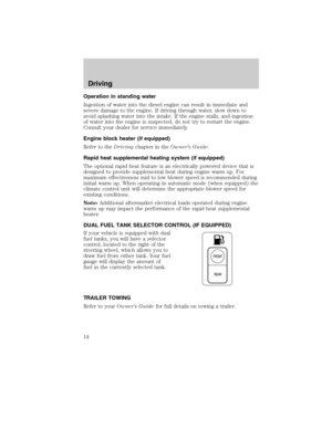
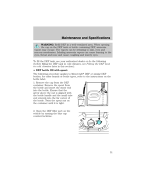
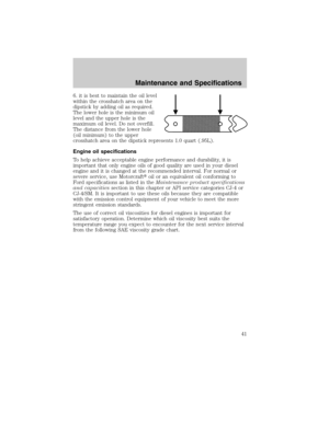
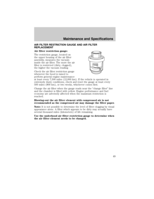
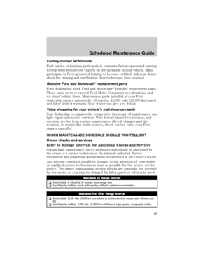
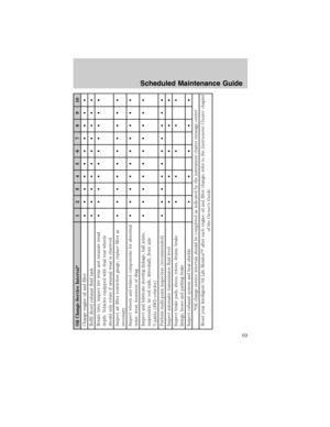
After installation of the new filter
element, reset the gauge by pressing
the reset button on top of the
gauge.
Note:Vehicle operation in heavy
snowfall or extreme rain conditions
may feed excessive amounts of
snow/water into the air intake
system. This could plug/soak the air
filter with snow and may cause the
engine to lose power and possibly
shut down.
The following actions are recommend after operating the vehicle up to
200 miles (320 km) in heavy snowfall or extreme rain:
•Snow:At the earliest opportunity, open the hood and clear all the
snow and ice from the air filter housing inlet (do NOT remove the
foam filter) and reset the air filter restriction gauge.
•Extreme rain:The air filter will dry after about 15–30 minutes at
highway speeds. At the earliest opportunity, open the hood and reset
the air filter restriction gauge.
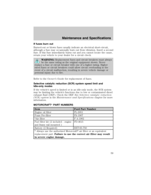
Air filter replacement:
When replacing the air filter element, use the Motorcraft�air filter
element listed inMotorcraft part numberslater in this chapter.
WARNING:To reduce the risk of vehicle damage and/or
personal burn injuries do not start your engine with the air filter
removed and do not remove it while the engine is running.
Failure to use the correct air filter element may result in severe
engine damage.
Maintenance and Specifications
50
2011 Econoline(eco)
Supplement, 1st Printing
USA(fus)
Page 51 of 90
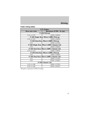
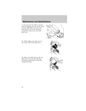
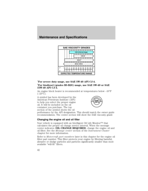
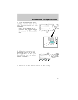
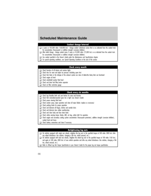
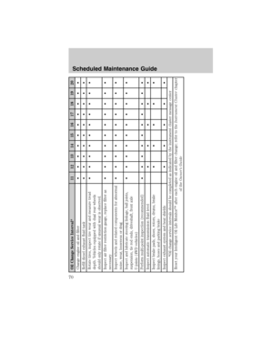
1. Locate the mass air flow sensor
electrical connector on the air inlet
tube. This connector will need to be
unplugged.
Unlock the locking clip on the
connector, then squeeze and pull
the connector off of the air inlet
tube.
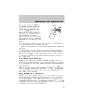
2. Release the four clamps that
secure the cover to the air filter
housing. Push the air filter cover
forward (away from you) and up
slightly to release it.
3. Remove the air filter element from the air filter housing.
Maintenance and Specifications
51
2011 Econoline(eco)
Supplement, 1st Printing
USA(fus)
Page 52 of 90
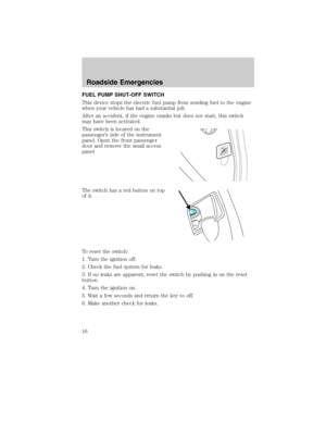
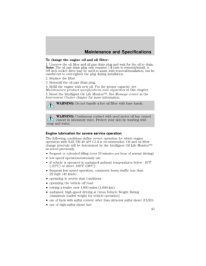
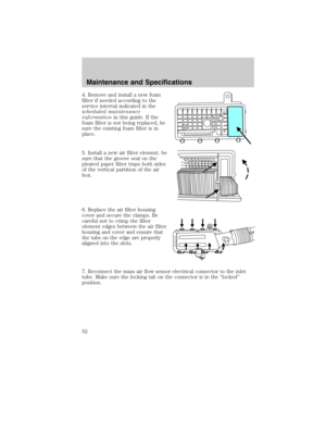
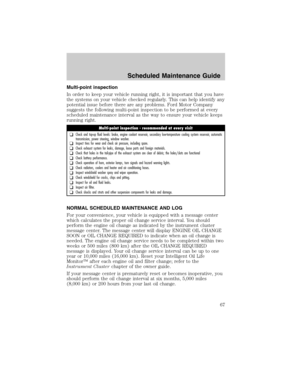
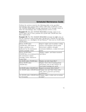
4. Remove and install a new foam
filter if needed according to the
service interval indicated in the
scheduled maintenance
informationin this guide. If the
foam filter is not being replaced, be
sure the existing foam filter is in
place.
5. Install a new air filter element. be
sure that the groove seal on the
pleated paper filter traps both sides
of the vertical partition of the air
box.
6. Replace the air filter housing
cover and secure the clamps. Be
careful not to crimp the filter
element edges between the air filter
housing and cover and ensure that
the tabs on the edge are properly
aligned into the slots.
7. Reconnect the mass air flow sensor electrical connector to the inlet
tube. Make sure the locking tab on the connector is in the “locked”
position.
Maintenance and Specifications
52
2011 Econoline(eco)
Supplement, 1st Printing
USA(fus)
Page 53 of 90
. The DPF
is an inline filter in the exhaust system which redu")
DIESEL EXHAUST SYSTEM: OXIDATION CATALYST/DIESEL
PARTICULATE FILTER SYSTEM
Your vehicle is equipped with a diesel particulate filter (DPF). The DPF
is an inline filter in the exhaust system which reduces carbon emissions
by trapping exhaust particles before they reach the tailpipe. The DPF
looks similar to a traditional exhaust catalyst, except larger, and is part
of the exhaust system under the vehicle. The DPF is coupled to a diesel
oxidation catalyst, that reduces the amount of harmful exhaust emitted
from the tailpipe. As soot gathers in the system it begins to restrict the
filter. The soot gathered inside the filter needs to be periodically cleaned.
The soot can be cleaned in two different ways; passive regeneration and
active regeneration. Both methods occur automatically and require no
actions from the driver/operator. During either one of these regeneration
methods you may notice an increase/change in exhaust noise/tone. At
certain times, the message center will display various messages related
to the DPF. SeeMessage centerin theInstrument Clusterchapter in
theOwner Guidefor more information.
Passive regeneration
In passive regeneration, the exhaust constituents / temperature are at an
appropriate level where some soot can be reduced or oxidized (burned)
thus cleaning the filter. This method occurs naturally as a result of
normal engine operating conditions (at varying levels due to drive
patterns).
Active regeneration
Once the DPF is full of exhaust particles, the engine control module will
command the exhaust system to clean the DPF through a process called
active regeneration. Active regeneration requires the engine computer to
raise the exhaust temperature to eliminate the particles. During cleaning,
the particles are converted to harmless gasses, and the DPF will then be
clean and ready to continue trapping exhaust particles.
The regeneration process operates more efficiently when the vehicle is
safely operated at least 30 mph (48 km/h) with a steady pedal for
approximately 20 minutes to complete the process. The frequency and
duration of regeneration will fluctuate as both are determined by how
you drive your vehicle, outside air temperature, and altitude. For most
driving, regeneration frequency will vary from 100 - 600 miles (161 -
966 km) between occurrences and each occurrence will last from 9 -
20 minutes. The duration of regeneration is usually reduced if a constant
speed above 30 mph (48 km/h) is maintained.
Maintenance and Specifications
53
2011 Econoline(eco)
Supplement, 1st Printing
USA(fus)
Page 54 of 90

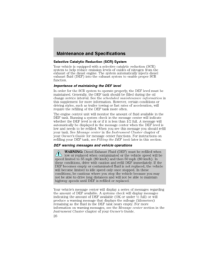
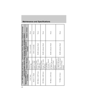
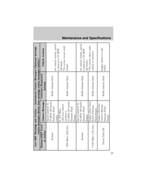
When the engine control module detects that the DPF is nearly full of
particulates and that the vehicle is not being operated in a manner to
allow effective automatic cleaning, the message center will display
several messages guiding the vehicle operator to drive to clean the DPF.
If the vehicle is operated in a manner to allow effective automatic
cleaning, the message center will display CLEANING EXHAUST FILTER,
which is the normal regeneration process. SeeMessage centerin the
Instrument Clusterchapter of theOwner Guidefor more information.
Filter service/maintenance
Over time a slight amount of ash will build up in the DPF which is not
removed during the regeneration process. The DPF may need to be
removed for ash cleaning at approximately 120,000 miles (193,000 km)
or greater (actual mileage can vary greatly depending upon
engine/vehicle operating conditions) and replaced with a new or
remanufactured (ash cleaned) part. The filter may need to be replaced
at approximately 250,000 miles (400,000 km) depending upon
engine/vehicle operating conditions. In both cases the engine control
system will set a service light
to inform you to bring the vehicle to
the dealer for service.
If there are any issues with the oxidation catalyst/DPF system a service
light
orwill be set by the engine control system to inform
you to bring the vehicle into a dealership for service.
Resonator/Tailpipe assembly maintenance
The diesel resonator tail-pipe assembly is a uniquely functioning device
that accompanies the Oxidation Catalyst/DPF assembly. The assembly
serves multiple functions. First it serves as an acoustic device to
attenuate exhaust noise. Second it provides an exit path for the exhaust
from the vehicle. It also is designed to help control the temperature of
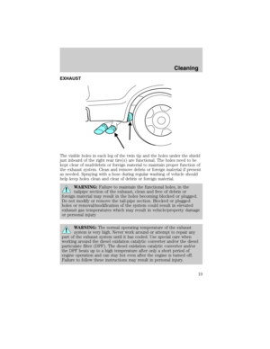
the exhaust during DPF regeneration events. The visible holes in each
leg of the twin tip and the holes under the shield just inboard of the
right rear tire(s) are functional. The holes need to be kept clear of
mud/debris or foreign material to maintain proper function of the
exhaust system. Clean and remove debris or foreign material if present
as needed. Spraying with a hose during regular washing of vehicle should
help keep holes clean and clear of debris or foreign material.
Note:Additions of aftermarket devices or modifications to the exhaust
system can reduce the effectiveness of the exhaust system as well as cause
damage to the exhaust system and/or engine. These actions may also affect
the vehicle’s warranty. See theWarranty Guidefor more information.
Maintenance and Specifications
54
2011 Econoline(eco)
Supplement, 1st Printing
USA(fus)
Page 55 of 90

WARNING:Failure to maintain the functional holes, in the
tailpipe section of the exhaust, clean and free of debris or
foreign material may result in the holes becoming blocked or plugged.
Do not modify or remove the tail-pipe section. Blocked or plugged
holes or removal/modification of the system could result in elevated
exhaust gas temperatures which may result in vehicle/property damage
or personal injury.
WARNING:The normal operating temperature of the exhaust
system is very high. Never work around or attempt to repair any
part of the exhaust system until it has cooled. Use special care when
working around the diesel oxidation catalytic converter and/or the diesel
particulate filter (DPF). The diesel oxidation catalytic converter and/or
the DPF heats up to a high temperature after only a short period of
engine operation and can stay hot even after the engine is turned off.
Failure to follow these instructions may result in personal injury.
EMISSION CONTROL SYSTEM(S) LAWS
In the U.S. federal law and certain state laws prohibit removing or
rendering inoperative emission control system(s). Similar federal or
provincial laws may apply in Canada. Ford recommends against any
vehicle modification without determining applicable law.
WARNING:Do not remove or alter the original equipment floor
covering or insulation between it and the metal floor of the
vehicle. The floor covering and insulation protect occupants of the
vehicle from the engine and exhaust system heat and noise. On
vehicles with no original equipment floor covering insulation, do not
carry passengers in a manner that permits prolonged skin contact with
the metal floor. Provide adequate insulation. Failure to follow these
instructions may result in fire or personal injury.
NOISE EMISSIONS WARRANTY, PROHIBITED TAMPERING ACTS
AND MAINTENANCE
On January 1, 1978, Federal regulation became effective governing the
noise emission on trucks over 10,000 lbs. (4,536 kg) GVWR (Gross
Vehicle Weight Rating). The following statements concerning prohibited
tampering acts and maintenance, and the noise warranty found in the
Warranty Guide, are applicable to complete chassis cabs over
10,000 lbs. (4,536 kg) GVWR.
Maintenance and Specifications
55
2011 Econoline(eco)
Supplement, 1st Printing
USA(fus)
Page 56 of 90
 The
removal or rendering inoperative by any person other than for purposes
of mainte")
Tampering with noise control system prohibited
Federal law prohibits the following acts or the causing thereof: (1) The
removal or rendering inoperative by any person other than for purposes
of maintenance, repair or replacement of any device or element of design
incorporated into any new vehicle for the purpose of noise control prior
to its sale or delivery to the ultimate purchaser or while it is in use, or
(2) the use of the vehicle after such device or element of design has
been removed or rendered inoperative by any person.
Among those acts which the U.S. Environmental Protection Agency may
presume to constitute tampering are the acts listed below:
•Removal of hood blanket, fender apron absorbers, fender apron
barriers, underbody noise shields or acoustically absorptive material.
•Tampering or rendering inoperative the engine speed governor, so as
to allow engine speed to exceed manufacturer’s specifications.
The complexity of the diesel engine makes it so the owner is discouraged
from attempting to perform maintenance other than the services
described in this supplement.
If you experience difficult starting, rough idling, excessive exhaust
smoke, a decrease in engine performance or excess fuel consumption,
perform the following checks:
•a plugged or disconnected air inlet system or engine air filter element.
•water in the fuel filter/water separator.
•a clogged fuel filter.
•contaminated fuel.
•air in the fuel system, due to loose connections.
•an open or pinched sensor hose.
•check engine oil level.
•wrong fuel or oil viscosity for climactic conditions.
If these checks do not help you correct the engine performance problem
you are experiencing, consult an authorized dealer.
Maintenance and Specifications
56
2011 Econoline(eco)
Supplement, 1st Printing
USA(fus)