2011 FORD SUPER DUTY lock
[x] Cancel search: lockPage 38 of 90
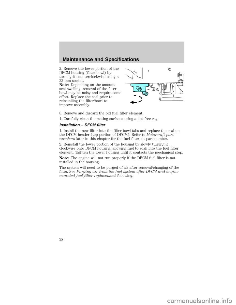
2. Remove the lower portion of the
DFCM housing (filter bowl) by
turning it counterclockwise using a
32 mm socket.
Note:Depending on the amount
seal swelling, removal of the filter
bowl may be noisy and require some
effort. Replace the seal prior to
reinstalling the filter/bowl to
improve assembly.
3. Remove and discard the old fuel filter element.
4. Carefully clean the mating surfaces using a lint-free rag.
Installation – DFCM filter
1. Install the new filter into the filter bowl tabs and replace the seal on
the DFCM header (top portion of DFCM). Refer toMotorcraft part
numberslater in this chapter for the fuel filter kit part number.
2. Reinstall the lower portion of the housing by slowly turning it
clockwise onto DFCM housing, allowing fuel to soak into the fuel filter
element. Tighten the lower housing until it contacts the mechanical stop.
Note:The engine will not run properly if the DFCM fuel filter is not
installed in the housing.
The system will need to be purged of air after removal/changing of the
filter. SeePurging air from the fuel system after DFCM and engine
mounted fuel filter replacementfollowing.
Maintenance and Specifications
38
2011 Econoline(eco)
Supplement, 1st Printing
USA(fus)
Page 39 of 90
Removal - Engine-mounted fuel filter
The engine-mounted fuel filter is a plastic disposable cartridge. To
remove it, do the following:
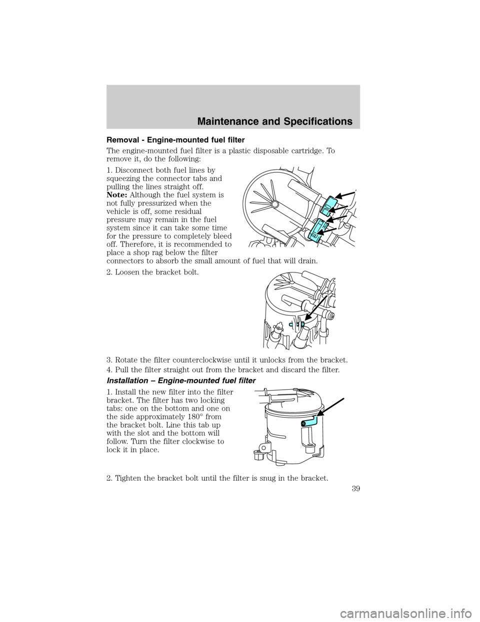
1. Disconnect both fuel lines by
squeezing the connector tabs and
pulling the lines straight off.
Note:Although the fuel system is
not fully pressurized when the
vehicle is off, some residual
pressure may remain in the fuel
system since it can take some time
for the pressure to completely bleed
off. Therefore, it is recommended to
place a shop rag below the filter
connectors to absorb the small amount of fuel that will drain.
2. Loosen the bracket bolt.
3. Rotate the filter counterclockwise until it unlocks from the bracket.
4. Pull the filter straight out from the bracket and discard the filter.
Installation – Engine-mounted fuel filter
1. Install the new filter into the filter
bracket. The filter has two locking
tabs: one on the bottom and one on
the side approximately 180° from
the bracket bolt. Line this tab up
with the slot and the bottom will
follow. Turn the filter clockwise to
lock it in place.
2. Tighten the bracket bolt until the filter is snug in the bracket.
Maintenance and Specifications
39
2011 Econoline(eco)
Supplement, 1st Printing
USA(fus)
Page 42 of 90
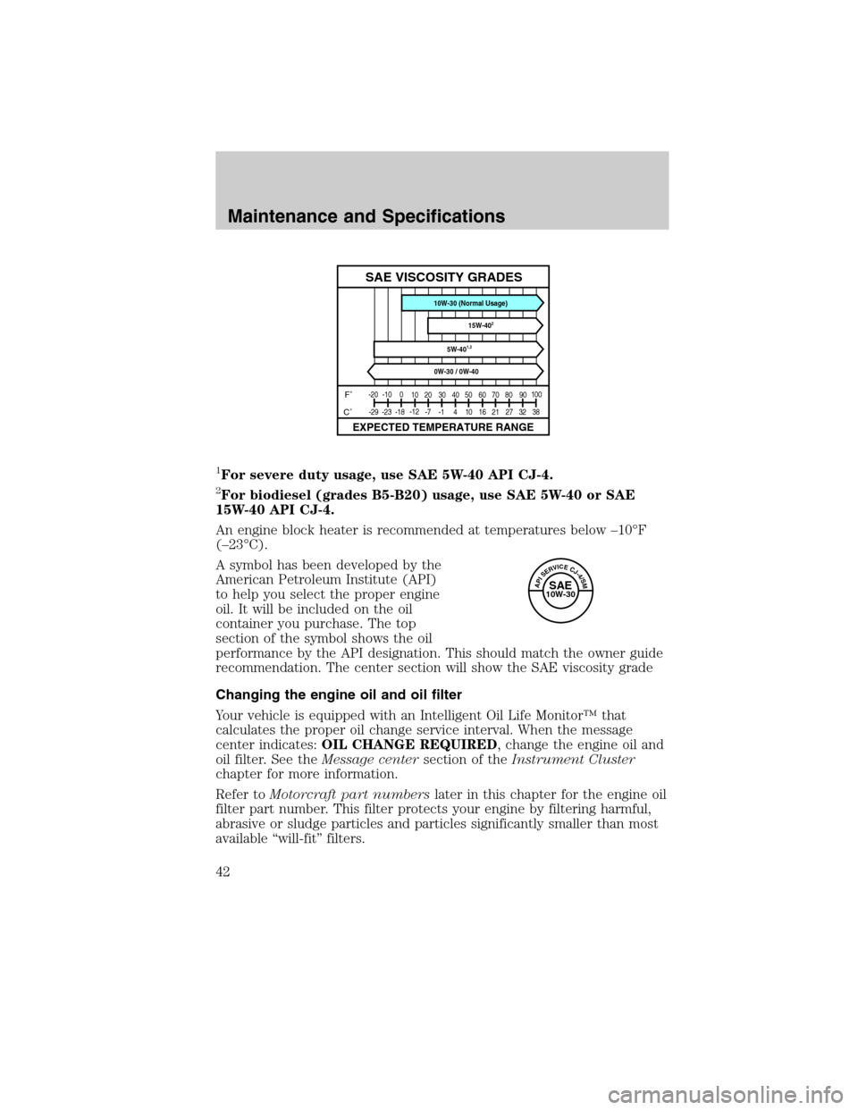
1For severe duty usage, use SAE 5W-40 API CJ-4.
2For biodiesel (grades B5-B20) usage, use SAE 5W-40 or SAE
15W-40 API CJ-4.
An engine block heater is recommended at temperatures below –10°F
(–23°C).
A symbol has been developed by the
American Petroleum Institute (API)
to help you select the proper engine
oil. It will be included on the oil
container you purchase. The top
section of the symbol shows the oil
performance by the API designation. This should match the owner guide
recommendation. The center section will show the SAE viscosity grade
Changing the engine oil and oil filter
Your vehicle is equipped with an Intelligent Oil Life Monitor™ that
calculates the proper oil change service interval. When the message
center indicates:OIL CHANGE REQUIRED, change the engine oil and
oil filter. See theMessage centersection of theInstrument Cluster
chapter for more information.
Refer toMotorcraft part numberslater in this chapter for the engine oil
filter part number. This filter protects your engine by filtering harmful,
abrasive or sludge particles and particles significantly smaller than most
available “will-fit” filters.
-20
-100
10 20 30
40
38 32 27 21 16 10 4 -1 -7 -12
-18 -23 -2950 60
7080 9010 0
SAE VISCOSITY GRADES
EXPECTED TEMPERATURE RANGE
F˚
C˚
5W-401,2
0W-30 / 0W-4015W-40
2
10W-30 (Normal Usage)
APISERVICECJ-4/SMSAE10W-30
Maintenance and Specifications
42
2011 Econoline(eco)
Supplement, 1st Printing
USA(fus)
Page 46 of 90
•Do not mix with recycled coolant unless from a Ford-approved
recycling process (seeUse of recycled engine coolantsection).
WARNING:To reduce the risk of personal injury, make sure the
engine is cool before unscrewing the coolant pressure relief cap.
The cooling system(s) are under pressure; steam and hot liquid can
come out forcefully when the cap is loosened slightly.
Add the proper mixture of coolant and distilled water to the cooling
system(s) by following these steps:
1. Before you remove the cap, turn the engine off and let it cool.
2. When the engine is cool, wrap a thick cloth around the cap. Slowly
turn cap counterclockwise until pressure begins to release.
3. Step back while the pressure releases.
4. When you are sure that all the pressure has been released, use the
cloth to turn it counterclockwise and remove the cap.
Engine and secondary cooling system refill procedure
The following procedure should be used when refilling the engine or
secondary cooling systems after it has been drained or become extremely
low.
1. Remove the pressure relief cap from the engine or secondary coolant
reservoir as previously outlined.
2. Slowly add a 50/50 mixture of coolant and distilled water to the
coolant reservoir until the coolant level is within the COLD FILL RANGE
as listed on the reservoir.
3. Reinstall the pressure relief cap.
4. Start and run the engine at 2,000 rpm for 2 minutes.
5. Shut engine off, and remove the pressure relief cap as previously
outlined.
6. If required, add a 50/50 mixture of coolant and distilled water to the
coolant reservoir until the coolant level is within the COLD FILL RANGE
as listed on the reservoir.
7. Engine cooling system: Repeat Step 3 until the coolant level has
stabilized (is no longer dropping after each step) AND the upper radiator
hose at the radiator is warm to the touch (indicating that the engine
thermostat is open and coolant is flowing through the radiator).
Secondary cooling system: Repeat Step 3 until the coolant level has
stabilized (is no longer dropping after each step) AND the lower
Maintenance and Specifications
46
2011 Econoline(eco)
Supplement, 1st Printing
USA(fus)
Page 51 of 90
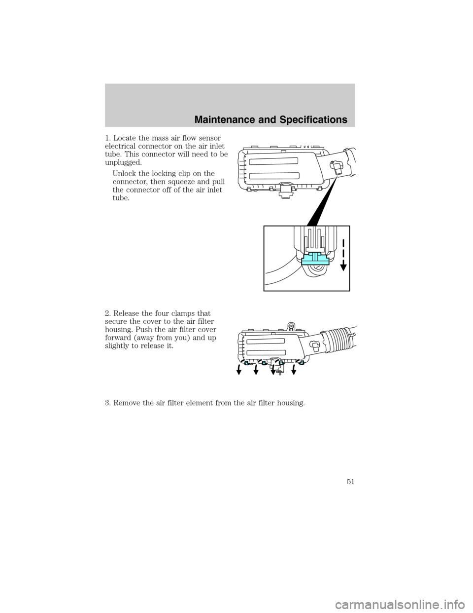
1. Locate the mass air flow sensor
electrical connector on the air inlet
tube. This connector will need to be
unplugged.
Unlock the locking clip on the
connector, then squeeze and pull
the connector off of the air inlet
tube.
2. Release the four clamps that
secure the cover to the air filter
housing. Push the air filter cover
forward (away from you) and up
slightly to release it.
3. Remove the air filter element from the air filter housing.
Maintenance and Specifications
51
2011 Econoline(eco)
Supplement, 1st Printing
USA(fus)
Page 52 of 90
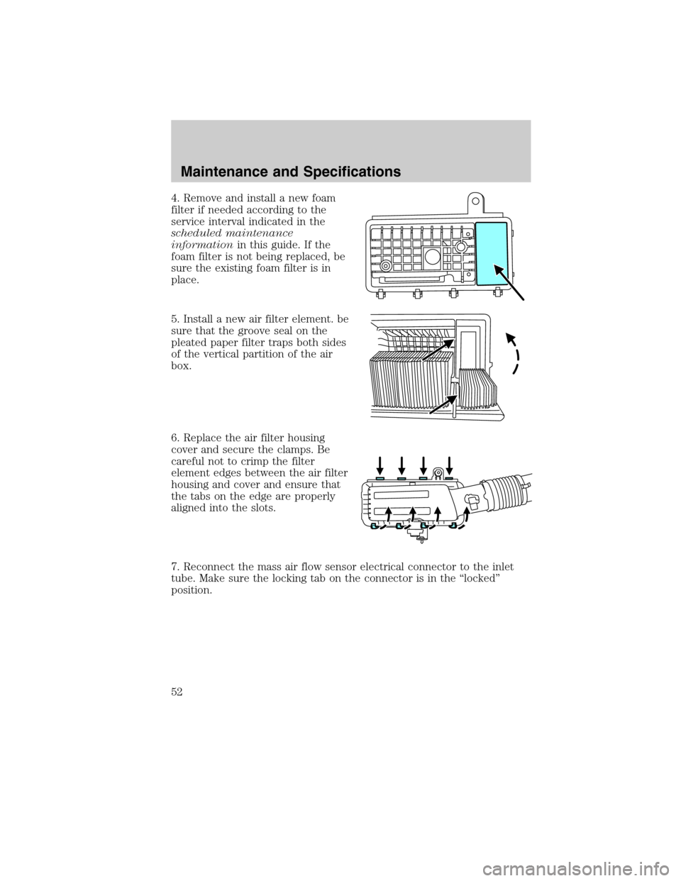
4. Remove and install a new foam
filter if needed according to the
service interval indicated in the
scheduled maintenance
informationin this guide. If the
foam filter is not being replaced, be
sure the existing foam filter is in
place.
5. Install a new air filter element. be
sure that the groove seal on the
pleated paper filter traps both sides
of the vertical partition of the air
box.
6. Replace the air filter housing
cover and secure the clamps. Be
careful not to crimp the filter
element edges between the air filter
housing and cover and ensure that
the tabs on the edge are properly
aligned into the slots.
7. Reconnect the mass air flow sensor electrical connector to the inlet
tube. Make sure the locking tab on the connector is in the “locked”
position.
Maintenance and Specifications
52
2011 Econoline(eco)
Supplement, 1st Printing
USA(fus)
Page 55 of 90
WARNING:Failure to maintain the functional holes, in the
tailpipe section of the exhaust, clean and free of debris or
foreign material may result in the holes becoming blocked or plugged.
Do not modify or remove the tail-pipe section. Blocked or plugged
holes or removal/modification of the system could result in elevated
exhaust gas temperatures which may result in vehicle/property damage
or personal injury.
WARNING:The normal operating temperature of the exhaust
system is very high. Never work around or attempt to repair any
part of the exhaust system until it has cooled. Use special care when
working around the diesel oxidation catalytic converter and/or the diesel
particulate filter (DPF). The diesel oxidation catalytic converter and/or
the DPF heats up to a high temperature after only a short period of
engine operation and can stay hot even after the engine is turned off.
Failure to follow these instructions may result in personal injury.
EMISSION CONTROL SYSTEM(S) LAWS
In the U.S. federal law and certain state laws prohibit removing or
rendering inoperative emission control system(s). Similar federal or
provincial laws may apply in Canada. Ford recommends against any
vehicle modification without determining applicable law.
WARNING:Do not remove or alter the original equipment floor
covering or insulation between it and the metal floor of the
vehicle. The floor covering and insulation protect occupants of the
vehicle from the engine and exhaust system heat and noise. On
vehicles with no original equipment floor covering insulation, do not
carry passengers in a manner that permits prolonged skin contact with
the metal floor. Provide adequate insulation. Failure to follow these
instructions may result in fire or personal injury.
NOISE EMISSIONS WARRANTY, PROHIBITED TAMPERING ACTS
AND MAINTENANCE
On January 1, 1978, Federal regulation became effective governing the
noise emission on trucks over 10,000 lbs. (4,536 kg) GVWR (Gross
Vehicle Weight Rating). The following statements concerning prohibited
tampering acts and maintenance, and the noise warranty found in the
Warranty Guide, are applicable to complete chassis cabs over
10,000 lbs. (4,536 kg) GVWR.
Maintenance and Specifications
55
2011 Econoline(eco)
Supplement, 1st Printing
USA(fus)
Page 58 of 90
•Try operating the starter switch several times. Should the switch be
corroded, this operation may clean the contacts or make the switch
temporarily operable until you can reach the dealer.
•If all electrical connections are tight and you need assistance to start,
refer toJump startingin theRoadside Emergencieschapter of your
Owner’s Guide.
If engine cranks but won’t start
Prolonged starter cranking (in excess of 10 seconds) could cause
damage to the starter motor.
•Check the fuel gauge. You may be out of fuel. If the gauge shows that
there is fuel in the tank, the trouble may be in the electrical system or
the fuel system. If equipped with an auxiliary tank, be sure that the
tank control switch is set for the tank with fuel and not on an empty
tank.
•Leaving the ignition key turned to on for over two minutes without
starting may make starting difficult because the glow plugs will cease
activation. Reset the system by turning the ignition key to off and
then back to on again.
If the engine runs hot
The following could cause the engine to overheat:
•Lack of coolant.
•Dirty cooling system.
•Plugged radiator fins, A/C condenser and/or oil cooler.
•Malfunctioning fan drive.
•Driving with frozen coolant.
•Sticking thermostat.
•Overloading or pulling heavy trailers during hot weather.
•Grill or radiator air blockage.
•Slipping or missing drive belt.
•Plugged or very dirty air filter.
Maintenance and Specifications
58
2011 Econoline(eco)
Supplement, 1st Printing
USA(fus)