Page 1879 of 2057

transaxle output shaft. The frequency of the
square-wave signal increases with the speed of
the transmission output shaft.
The OSS sensor picks up the speed at the gear of
the parking lock.
The TCM uses the information from the OSS
sensor for the following parameters:
• Calculation of the degree of torque reductionthat needs to be requested by the PCM during
shifting.
• Calculation of the shift points.
• Calculation of the engaging and disengaging point for the TCC (lock-up function).
• Calculation of the current gear ratios by comparison of the TSS sensor signal.
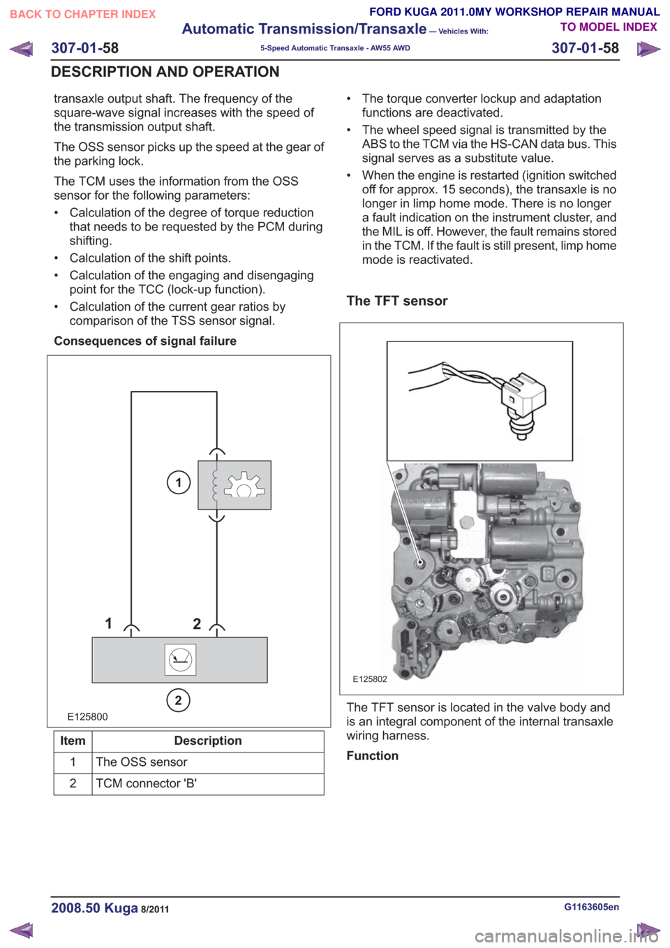
Consequences of signal failure
E125800
1 2
2
1
Description
Item
The OSS sensor
1
TCM connector 'B'
2 • The torque converter lockup and adaptation
functions are deactivated.
• The wheel speed signal is transmitted by the ABS to the TCM via the HS-CAN data bus. This
signal serves as a substitute value.
• When the engine is restarted (ignition switched off for approx. 15 seconds), the transaxle is no
longer in limp home mode. There is no longer
a fault indication on the instrument cluster, and
the MIL is off. However, the fault remains stored
in the TCM. If the fault is still present, limp home
mode is reactivated.
The TFT sensor
E125802
The TFT sensor is located in the valve body and
is an integral component of the internal transaxle
wiring harness.
Function
G1163605en2008.50 Kuga8/2011
307-01- 58
Automatic Transmission/Transaxle
— Vehicles With:
5-Speed Automatic Transaxle - AW55 AWD
307-01- 58
DESCRIPTION AND OPERATION
TO MODEL INDEX
BACK TO CHAPTER INDEX
FORD KUGA 2011.0MY WORKSHOP REPAIR MANUAL
Page 1950 of 2057

Transfer Case – System Operation and Component Description
System Operation
1
2
3
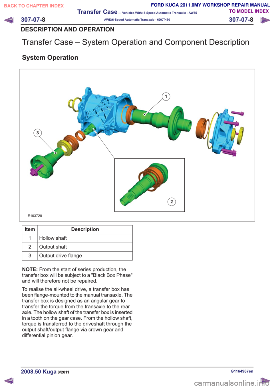
E103728
Description
Item
Hollow shaft
1
Output shaft
2
Output drive flange
3
NOTE: From the start of series production, the
transfer box will be subject to a "Black Box Phase"
and will therefore not be repaired.
To realise the all-wheel drive, a transfer box has
been flange-mounted to the manual transaxle. The
transfer box is designed as an angular gear to
transfer the torque from the transaxle to the rear
axle. The hollow shaft of the transfer box is inserted
in a tooth on the gear case. From the hollow shaft,
torque is transferred to the driveshaft through the
output shaft/output flange via crown gear and
differential pinion gear.
G1164987en2008.50 Kuga8/2011
307-07- 8
Transfer Case
— Vehicles With: 5-Speed Automatic Transaxle - AW55
AWD/6-Speed Automatic Transaxle - 6DCT450
307-07- 8
DESCRIPTION AND OPERATION
TO MODEL INDEX
BACK TO CHAPTER INDEX
FORD KUGA 2011.0MY WORKSHOP REPAIR MANUAL
Page 1992 of 2057
Fuel Tank Filler Pipe
General EquipmentFluid ContainerGeneral EquipmentFuel Tank Draining Equipment
Hose Clamp Remover/Installer
Removal
WARNING: Make sure that the fuel tank is
no more than 3/4 full.
NOTE: Removal steps in this procedure may
contain installation details.
1. Remove the rear wheel on right-hand side.
Refer to: Wheel and Tire (204-04 Wheels and
Tires, Removal and Installation).
2. WARNING: Be prepared to collect escaping fluid.
CAUTION: Use suitable paper to absorb
any escaping fluid.
General Equipment: Hose Clamp Remover/Installer
E117531
3. Torque: 10Nm
x2x2
E117532
G1000790en2008.50 Kuga8/2011
310-01- 12
Fuel Tank and Lines
310-01- 12
REMOVAL AND INSTALLATION
TO MODEL INDEX
BACK TO CHAPTER INDEX
FORD KUGA 2011.0MY WORKSHOP REPAIR MANUAL