Page 2029 of 2057

412-01-42
Heater Core and Evaporator Core Housing .......................................................................
412-01-45
(34 364 0)
Heater Core — RHD ........................................................................\
...............
412-01-53
Suction Accumulator ........................................................................\
...................................
412-01-56
Suction Accumulator to Air Conditioning (A/C) Compressor Line ......................................
412-01-57
Suction Accumulator to Air Conditioning (A/C) Compressor Line — 2.5L Duratec
(147kW/200PS) - VI5 ........................................................................\
................................
412-01-58
Low-Pressure Cutoff Switch ........................................................................\
.......................
412-01-59
High-Pressure Cutoff Switch ........................................................................\
.......................
412-01-60
Evaporator ........................................................................\
..................................................
412-01-62
Evaporator Outlet Line ........................................................................\
................................
412-01-65
Evaporator Core Orifice ........................................................................\
..............................
412-01-68
Condenser to Evaporator Line........................................................................\
....................
412-01-71
(34 300 0)
Climate Control Assembly — Vehicles With: Manual Temperature Control ....
412-01-72
(34 300 0)
Climate Control Assembly — Vehicles With: Automatic Temperature Control .
412-01-73
(34 485 4)
Footwell Air Discharge Temperature Sensor ..................................................
412-01-74
Center Register Air Discharge Temperature Sensor ..........................................................
412-01-75
In-Vehicle Temperature Sensor ........................................................................\
..................
412-01-76
(34 676 0)
Ambient Air Temperature Sensor ...................................................................
412-01-77
(34 665 0)
Sunload Sensor ........................................................................\
......................
412-01-78
(34 591 0)
Footwell Vent/Duct Blend Door Actuator — RHD ...........................................
412-01-79
(34 606 0)
Air Inlet Blend Door Actuator ........................................................................\
..
412-01-80
(34 608 0)
Driver Side Temperature Blend Door Actuator ...............................................
412-01-81
(34 608 0)
Passenger Side Temperature Blend Door Actuator .......................................
412-01-82
(34 591 0)
Defrost Vent/Register Blend Door Actuator — RHD ......................................
412-01-2
Climate Control
412-01- 2
.
TO MODEL INDEX
BACK TO CHAPTER INDEX
PAGE 2 OF 2 FORD KUGA 2011.0MY WORKSHOP REPAIR MANUAL
Page 2037 of 2057

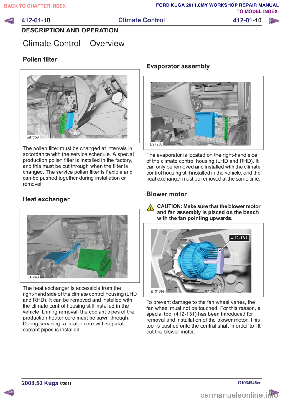
Climate Control – Overview
Pollen filter
E97258
The pollen filter must be changed at intervals in
accordance with the service schedule. A special
production pollen filter is installed in the factory,
and this must be cut through when the filter is
changed. The service pollen filter is flexible and
can be pushed together during installation or
removal.
Heat exchanger
E97249
The heat exchanger is accessible from the
right-hand side of the climate control housing (LHD
and RHD). It can be removed and installed with
the climate control housing still installed in the
vehicle. During removal, the coolant pipes of the
production heater core must be sawn through.
During servicing, a heater core with separate
coolant pipes is installed.
Evaporator assembly
E97250
The evaporator is located on the right-hand side
of the climate control housing (LHD and RHD). It
can only be removed and installed with the climate
control housing still installed in the vehicle, and the
heat exchanger must be removed at the same time.
Blower motor
CAUTION: Make sure that the blower motor
and fan assembly is placed on the bench
with the fan pointing upwards.
412-131
E101398
To prevent damage to the fan wheel vanes, the
fan wheel must not be touched. For this reason, a
special tool (412-131) has been introduced for
removal and installation of the blower motor. This
tool is pushed onto the central shaft in order to lift
out the blower motor.
G1034945en2008.50 Kuga8/2011
412-01-10
Climate Control
412-01- 10
DESCRIPTION AND OPERATION
TO MODEL INDEX
BACK TO CHAPTER INDEX
FORD KUGA 2011.0MY WORKSHOP REPAIR MANUAL
Page 2047 of 2057
Description
Item
Blower motorRefertoComponentDescription:(page
26)
1
Pollen filterRefertoComponentDescription:(page
24)
2
Evaporator assembly
3
Heat exchanger
4
Electric booster heater (if equipped)
5Description
Item
Temperature blend door motor
6
Air distribution flap, demister vents
7
Air distribution door - center vents
8
Air distribution door - footwell
9
Air intake door
10
Air duct, demister vents
11
Air passages - center vents
12
Air ducts, rear footwell
13
Air flow - defroster vents
12
E69659
Description
Item
Warm air
1
Cold air
2
G1034947en2008.50 Kuga8/2011
412-01- 20
Climate Control
412-01- 20
DESCRIPTION AND OPERATION
TO MODEL INDEX
BACK TO CHAPTER INDEX
FORD KUGA 2011.0MY WORKSHOP REPAIR MANUAL