2011 FORD KUGA steering system
[x] Cancel search: steering systemPage 1298 of 2057
Front Drive Halfshafts
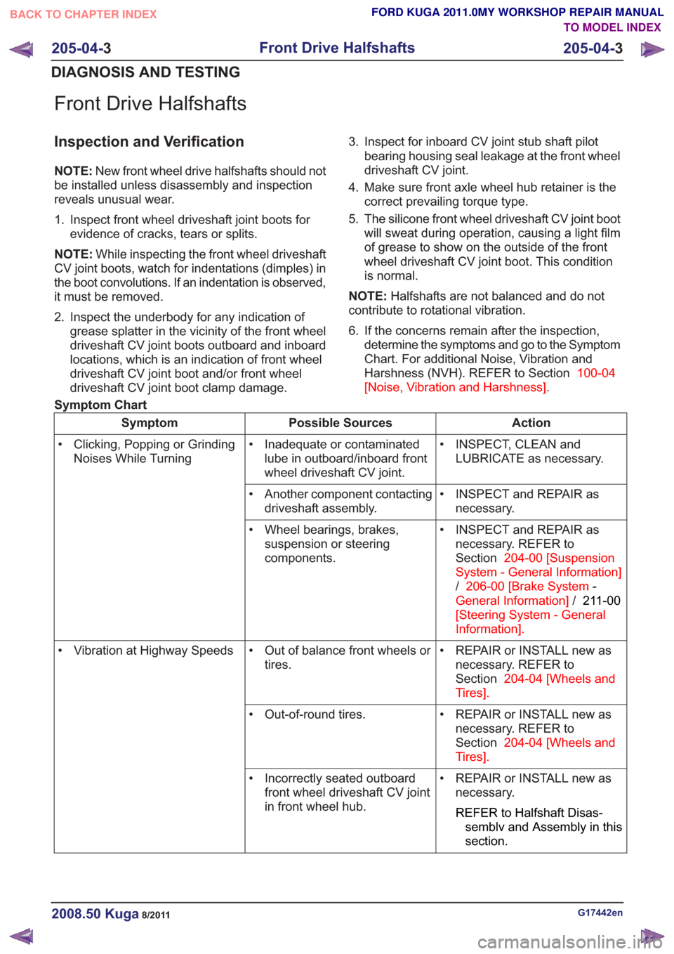
Inspection and Verification
NOTE:New front wheel drive halfshafts should not
be installed unless disassembly and inspection
reveals unusual wear.
1. Inspect front wheel driveshaft joint boots for evidence of cracks, tears or splits.
NOTE: While inspecting the front wheel driveshaft
CV joint boots, watch for indentations (dimples) in
the boot convolutions. If an indentation is observed,
it must be removed.
2. Inspect the underbody for any indication of grease splatter in the vicinity of the front wheel
driveshaft CV joint boots outboard and inboard
locations, which is an indication of front wheel
driveshaft CV joint boot and/or front wheel
driveshaft CV joint boot clamp damage. 3. Inspect for inboard CV joint stub shaft pilot
bearing housing seal leakage at the front wheel
driveshaft CV joint.
4. Make sure front axle wheel hub retainer is the correct prevailing torque type.
5. The silicone front wheel driveshaft CV joint boot will sweat during operation, causing a light film
of grease to show on the outside of the front
wheel driveshaft CV joint boot. This condition
is normal.
NOTE: Halfshafts are not balanced and do not
contribute to rotational vibration.
6. If the concerns remain after the inspection, determine the symptoms and go to the Symptom
Chart. For additional Noise, Vibration and
Harshness (NVH). REFER to Section 100-04
[Noise, Vibration and Harshness] .
Symptom Chart
Action
Possible Sources
Symptom
• INSPECT, CLEAN andLUBRICATE as necessary.
• Inadequate or contaminated
lube in outboard/inboard front
wheel driveshaft CV joint.
• Clicking, Popping or Grinding
Noises While Turning
• INSPECT and REPAIR asnecessary.
• Another component contacting
driveshaft assembly.
• INSPECT and REPAIR asnecessary. REFER to
Section 204-00 [Suspension
System - General Information]
/ 206-00 [Brake System -
General Information] /211-00
[Steering System - General
Information] .
• Wheel bearings, brakes,
suspension or steering
components.
• REPAIR or INSTALL new asnecessary. REFER to
Section 204-04 [Wheels and
Tires] .
• Out of balance front wheels or
tires.
• Vibration at Highway Speeds
• REPAIR or INSTALL new asnecessary. REFER to
Section 204-04 [Wheels and
Tires] .
• Out-of-round tires.
• REPAIR or INSTALL new asnecessary.
REFER to Halfshaft Disas-
semblv and Assembly in this
section.
• Incorrectly seated outboard
front wheel driveshaft CV joint
in front wheel hub.
G17442en2008.50 Kuga8/2011
205-04- 3
Front Drive Halfshafts
205-04- 3
DIAGNOSIS AND TESTING
TO MODEL INDEX
BACK TO CHAPTER INDEX
FORD KUGA 2011.0MY WORKSHOP REPAIR MANUAL
Page 1419 of 2057
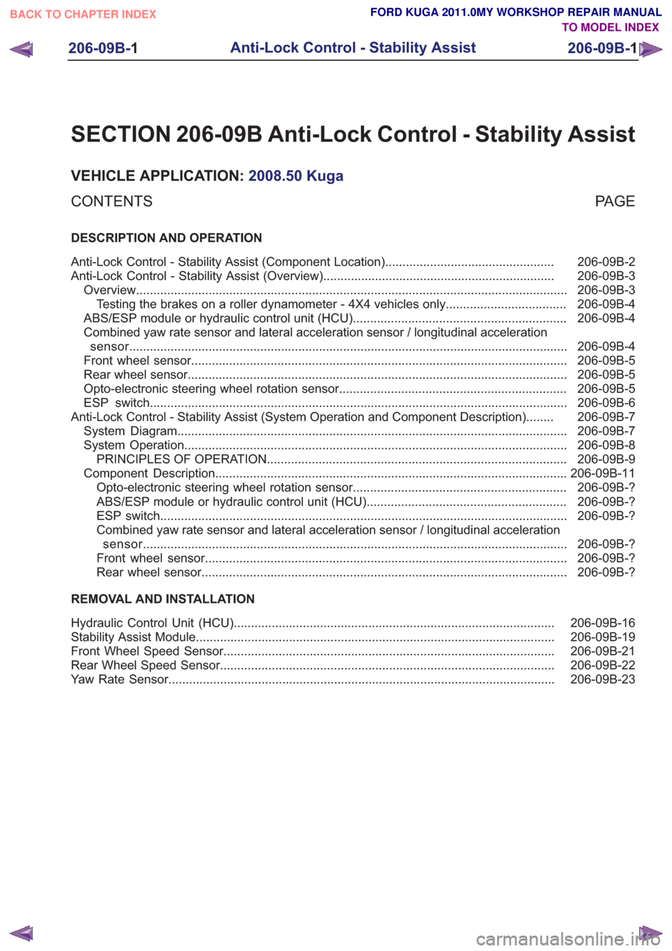
SECTION 206-09B Anti-Lock Control - Stability Assist
VEHICLE APPLICATION:2008.50 Kuga
PA G E
CONTENTS
DESCRIPTION AND OPERATION
206-09B-2
Anti-Lock Control - Stability Assist (Component Location) .................................................
206-09B-3
Anti-Lock Control - Stability Assist (Overview) ...................................................................
206-09B-3
Overview ........................................................................\
.....................................................
206-09B-4
Testing the brakes on a roller dynamometer - 4X4 vehicles only ...................................
206-09B-4
ABS/ESP module or hydraulic control unit (HCU) ..............................................................
206-09B-4
Combined yaw rate sensor and lateral acceleration sensor / longitudinal acceleration
sensor ........................................................................\
.......................................................
206-09B-5
Front wheel sensor ........................................................................\
.....................................
206-09B-5
Rear wheel sensor ........................................................................\
......................................
206-09B-5
Opto-electronic steering wheel rotation sensor ..................................................................
206-09B-6
ESP switch ........................................................................\
.................................................
206-09B-7
Anti-Lock Control - Stability Assist (System Operation and Component Description) ........
206-09B-7
System Diagram ........................................................................\
.........................................
206-09B-8
System Operation ........................................................................\
.......................................
206-09B-9
PRINCIPLES OF OPERATION ........................................................................\
...............
206-09B-11
Component Description ........................................................................\
..............................
206-09B-?
Opto-electronic steering wheel rotation sensor ..............................................................
206-09B-?
ABS/ESP module or hydraulic control unit (HCU) ..........................................................
206-09B-?
ESP switch ........................................................................\
..............................................
206-09B-?
Combined yaw rate sensor and lateral acceleration sensor / longitudinal acceleration
sensor........................................................................\
................................................... 206-09B-?
Front wheel sensor ........................................................................\
.................................
206-09B-?
Rear wheel sensor ........................................................................\
..................................
REMOVAL AND INSTALLATION 206-09B-16
Hydraulic Control Unit (HCU) ........................................................................\
.....................
206-09B-19
Stability Assist Module ........................................................................\
................................
206-09B-21
Front Wheel Speed Sensor ........................................................................\
........................
206-09B-22
Rear Wheel Speed Sensor ........................................................................\
.........................
206-09B-23
Yaw Rate Sensor ........................................................................\
........................................
206-09B-1
Anti-Lock Control - Stability Assist
206-09B- 1
.
TO MODEL INDEX
BACK TO CHAPTER INDEX
FORD KUGA 2011.0MY WORKSHOP REPAIR MANUAL
Page 1428 of 2057
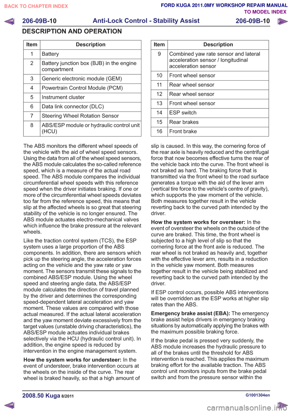
Description
Item
Battery
1
Battery junction box (BJB) in the engine
compartment
2
Generic electronic module (GEM)
3
Powertrain Control Module (PCM)
4
Instrument cluster
5
Data link connector (DLC)
6
Steering Wheel Rotation Sensor
7
ABS/ESP module or hydraulic control unit
(HCU)
8Description
Item
Combined yaw rate sensor and lateral
acceleration sensor / longitudinal
acceleration sensor
9
Front wheel sensor
10
Rear wheel sensor
11
Rear wheel sensor
12
Front wheel sensor
13
ESP switch
14
Rear brakes
15
Front brake
16
The ABS monitors the different wheel speeds of
the vehicle with the aid of wheel speed sensors.
Using the data from all of the wheel speed sensors,
the ABS module calculates the so-called reference
speed, which is a measure of the actual road
speed. The ABS module compares the individual
circumferential wheel speeds with this reference
speed when the driver initiates braking. If one or
more of the circumferential wheel speeds deviates
too far from the reference speed, this means that
slip at the affected wheels is so great that steering
stability of the vehicle is no longer ensured. The
ABS module actuates electro-mechanical valves
which influence the brake pressure at the relevant
wheels.
Like the traction control system (TCS), the ESP
system uses a large proportion of the ABS
components. In addition, there are sensors which
pick up the steering angle, the acceleration forces
acting on the vehicle and the yaw rate or yaw
moment. The sensors transmit these signals to the
combined ABS/ESP module. Using the wheel
speed and steering angle data, the ABS/ESP
module calculates the direction of travel planned
by the driver and determines the corresponding
speed-dependent lateral acceleration and yaw
moment. These values are compared with those
actual measured. If the actual lateral acceleration
and the yaw moment deviate excessively from the
target values (unstable driving characteristics), the
ABS/ESP module actuates individual brakes
selectively via the HCU (hydraulic control unit). In
addition, the engine speed is reduced by
intervention in the engine management system.
How the system works for understeer: In the
event of understeer, brake intervention occurs at
the wheels on the inside of the curve. The rear
wheel is braked heavily, so that a high amount of slip is caused. In this way, the cornering force of
the rear axle is heavily reduced and the centrifugal
force that now becomes effective turns the rear of
the vehicle back into the curve. The front wheel is
not braked as hard. The braking force that is
transmitted via the front wheel to the road surface
generates a torque with the aid of the lever arm
(vertical tire force to the vehicle's centre of gravity),
which supports the yaw moment of the vehicle.
Both measures together result in the vehicle
reverting back to the curved path intended by the
driver.
How the system works for oversteer:
In the
event of oversteer the wheels on the outside of the
curve are braked. This time, the front wheel is
subjected to a high level of slip so that the
cornering force at the front axle is reduced. The
rear wheel is not braked as heavily and, together
with the effective lever arm, results in a reduction
in the vehicle yaw moment. Both measures
together result in the vehicle being stabilized and
reverting back to the curved path intended by the
driver.
If ESP control occurs, possible ABS interventions
will be overridden as the ESP works at higher slip
rates than the ABS.
Emergency brake assist (EBA): The emergency
brake assist helps drivers in emergency braking
situations by automatically applying the brakes with
the maximum possible braking force.
If the brake pedal is pressed very suddenly, the
ABS module increases the hydraulic pressure to
all of the brakes until the threshold for ABS
intervention is reached. This applies the maximum
braking effort for the available traction. The ABS
control unit monitors inputs from the brake pedal
switch and from the pressure sensor within the
G1001304en2008.50 Kuga8/2011
206-09B- 10
Anti-Lock Control - Stability Assist
206-09B- 10
DESCRIPTION AND OPERATION
TO MODEL INDEX
BACK TO CHAPTER INDEX
FORD KUGA 2011.0MY WORKSHOP REPAIR MANUAL
Page 1429 of 2057
HCU to check for sudden actuation of the brakes.
With the brake pedal pressed, the ABS module
triggers emergency braking if the rate of increase
of hydraulic pressure exceeds the predetermined
limit.
If the brake pedal is pressed so hard that the ABS
becomes active on the front wheels then the ABS
control unit increases the pressure to the rear
wheel brakes up to the ABS intervention threshold.
EBA operation continues until the driver releases
the brake pedal sufficiently for the hydraulic
pressure in the HCU to drop below a threshold
value stored in the ABS module.
Trailer stability control:If the vehicle is ordered
with a trailer coupling then the Trailer Stability
Control function is integrated in the ESP. The ESP
detects snaking when driving with a trailer and
reduces the speed of the vehicle and trailer through
adapted braking and, if necessary, by also reducing
the engine output until the snaking movement of
the trailer is corrected.
Roll-over protection: The ESP dynamically
determines the tipping tendency of the vehicle and
works in conjunction with the EBA system to
prevent the vehicle from tipping over during
dynamic maneuvers like lane changing or while
negotiating bends.
Emergency brake light: The emergency brake
light automatically switches on the hazard flasher
system to warn drivers of other vehicles that
emergency braking is being initiated. Based on a
defined delay value, the ABS/ESP module sends
a signal to the generic electronic module (GEM)
via the CAN data bus. The GEM activates the
hazard flasher system, that then flashes 7 times.
Prerequisites for activation of the emergency brake
light are:
• The speed is higher than 50 km/h.
• The brake pedal is being actuated.
• The deceleration is greater than 9 m/s².
To prevent activation on snow or ice, for example,
the following prerequisites must be met:
• The speed is higher than 50 km/h.
• The brake pedal is being actuated.
• ABS regulation takes place.
• The deceleration is greater than 6 m/s².
Tire pressure monitoring system: The tire
pressure monitoring system used in the Kuga is
able to detect loss of air in a tire at an early stage
and warn the driver. Because it can only compare
the behaviour of the tyres with each other, it is not possible to draw conclusions about the absolute
tyre pressure. It is also not possible to monitor the
spare tyre pressure. In order for the system to
operate correctly, the tyre pressures must be
regularly checked and corrected and the system
subsequently initialised (see below).
The tire pressure monitoring system used here,
depending on the equipment level, is built into the
anti-lock braking system (ABS) as an extra function
and therefore does not have its own sensors.
The ABS module measures the loss of pressure
in the tyres by calculation using the wheel speed
sensors of the ABS system. If a tyre loses
pressure, its diameter decreases and the speed of
the wheel therefore increases. If the ABS module
detects such a loss in pressure, it sends a signal
to the instrument cluster via the CAN bus and a
warning message is displayed in the message
centre. The warning threshold depends among
other things on the dimension of the tyres being
used, the vehicle operating conditions and the
status at the last initialisation. Since neither the
absolute tyre pressure nor the position of the tyre
is known, the pressure of all the tyres must be
checked and the system re-initialised after a tyre
pressure warning. If necessary, the cause of the
loss of pressure must be investigated.
Regular tyre pressure checks are still necessary.
The system must be initialised after a tyre is
changed, winter or summer tyres fitted, the
pressures corrected or adjusted to suit the vehicle
load. This can be done by the driver using the
driver information system. For further information,
see: Owner’s Manual.
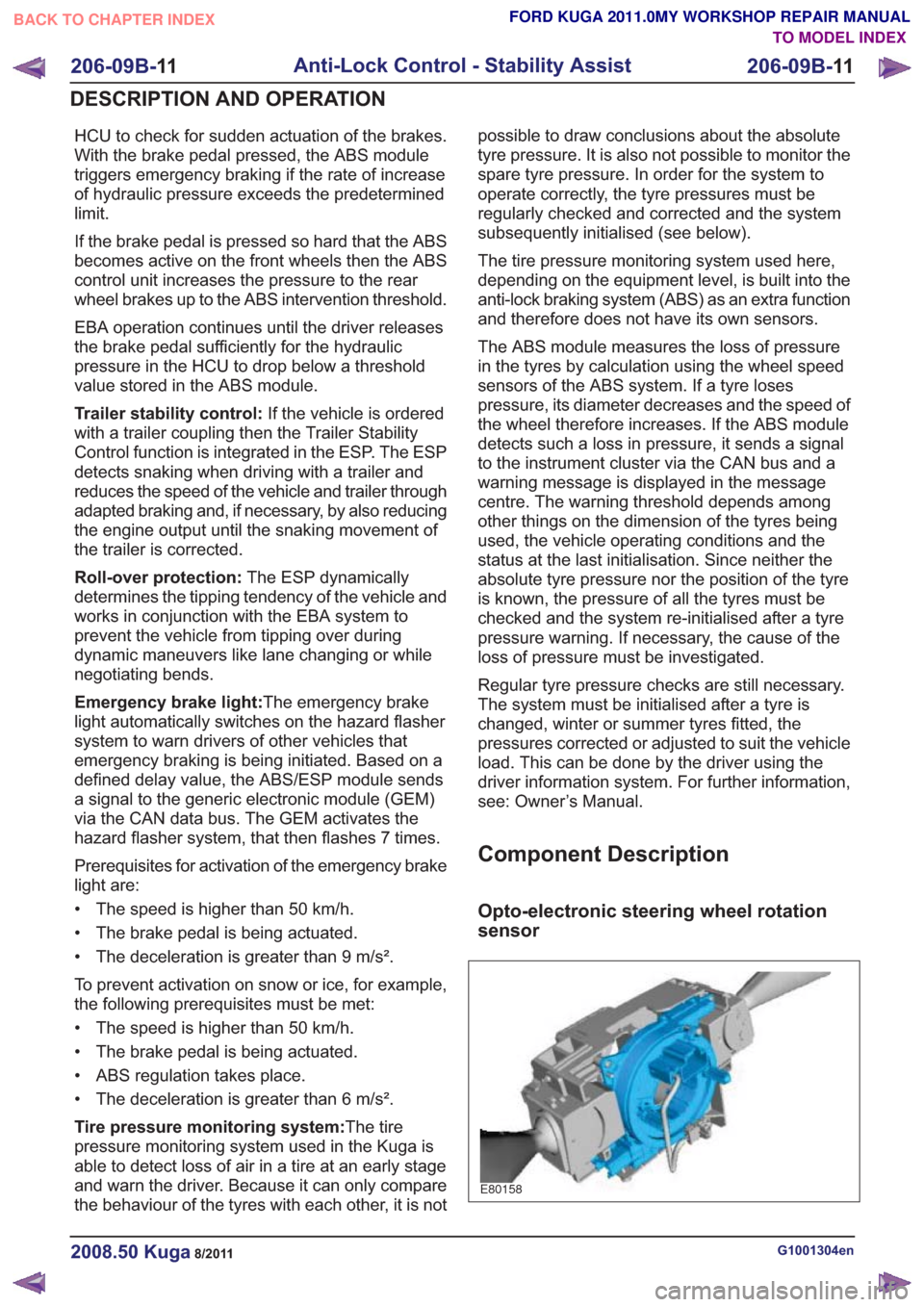
Component Description
Opto-electronic steering wheel rotation
sensor
E80158
G1001304en2008.50 Kuga8/2011
206-09B-
11
Anti-Lock Control - Stability Assist
206-09B- 11
DESCRIPTION AND OPERATION
TO MODEL INDEX
BACK TO CHAPTER INDEX
FORD KUGA 2011.0MY WORKSHOP REPAIR MANUAL
Page 1430 of 2057
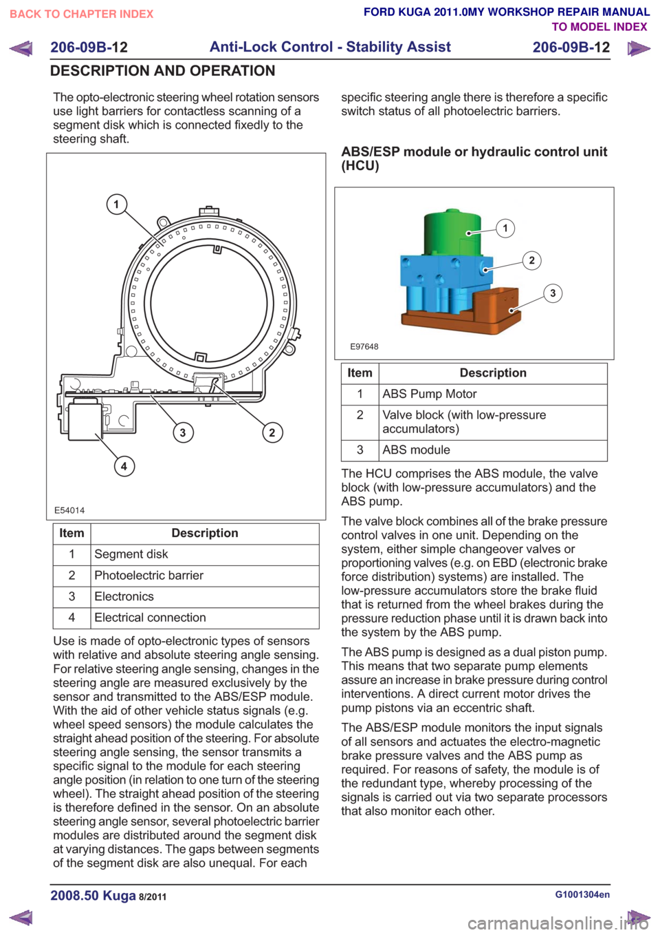
The opto-electronic steering wheel rotation sensors
use light barriers for contactless scanning of a
segment disk which is connected fixedly to the
steering shaft.
E54014
1
23
4
Description
Item
Segment disk
1
Photoelectric barrier
2
Electronics
3
Electrical connection
4
Use is made of opto-electronic types of sensors
with relative and absolute steering angle sensing.
For relative steering angle sensing, changes in the
steering angle are measured exclusively by the
sensor and transmitted to the ABS/ESP module.
With the aid of other vehicle status signals (e.g.
wheel speed sensors) the module calculates the
straight ahead position of the steering. For absolute
steering angle sensing, the sensor transmits a
specific signal to the module for each steering
angle position (in relation to one turn of the steering
wheel). The straight ahead position of the steering
is therefore defined in the sensor. On an absolute
steering angle sensor, several photoelectric barrier
modules are distributed around the segment disk
at varying distances. The gaps between segments
of the segment disk are also unequal. For each specific steering angle there is therefore a specific
switch status of all photoelectric barriers.
ABS/ESP module or hydraulic control unit
(HCU)
E97648
1
2
3
Description
Item
ABS Pump Motor
1
Valve block (with low-pressure
accumulators)
2
ABS module
3
The HCU comprises the ABS module, the valve
block (with low-pressure accumulators) and the
ABS pump.
The valve block combines all of the brake pressure
control valves in one unit. Depending on the
system, either simple changeover valves or
proportioning valves (e.g. on EBD (electronic brake
force distribution) systems) are installed. The
low-pressure accumulators store the brake fluid
that is returned from the wheel brakes during the
pressure reduction phase until it is drawn back into
the system by the ABS pump.
The ABS pump is designed as a dual piston pump.
This means that two separate pump elements
assure an increase in brake pressure during control
interventions. A direct current motor drives the
pump pistons via an eccentric shaft.
The ABS/ESP module monitors the input signals
of all sensors and actuates the electro-magnetic
brake pressure valves and the ABS pump as
required. For reasons of safety, the module is of
the redundant type, whereby processing of the
signals is carried out via two separate processors
that also monitor each other.
G1001304en2008.50 Kuga8/2011
206-09B- 12
Anti-Lock Control - Stability Assist
206-09B- 12
DESCRIPTION AND OPERATION
TO MODEL INDEX
BACK TO CHAPTER INDEX
FORD KUGA 2011.0MY WORKSHOP REPAIR MANUAL
Page 1442 of 2057
SECTION 211-00 Steering System - General
Information
VEHICLE APPLICATION:2008.50 Kuga
PA G E
CONTENTS
DIAGNOSIS AND TESTING
211-00-2
Steering System ........................................................................\
.........................................
211-00-2
Inspection and Verification ........................................................................\
..........................
211-00-2
Components Tests ........................................................................\
......................................
211-00-6
Steering Gear Checks After a Collision ........................................................................\
......
GENERAL PROCEDURES 211-00-8
Power Steering System Flushing ........................................................................\
...............
211-00-9
Power Steering System Filling ........................................................................\
....................
211-00-10
Power Steering System Vacuum Bleeding ........................................................................\
.
211-00-1
Steering System - General Information
211-00- 1
.
TO MODEL INDEX
BACK TO CHAPTER INDEX
FORD KUGA 2011.0MY WORKSHOP REPAIR MANUAL
Page 1443 of 2057
Steering System
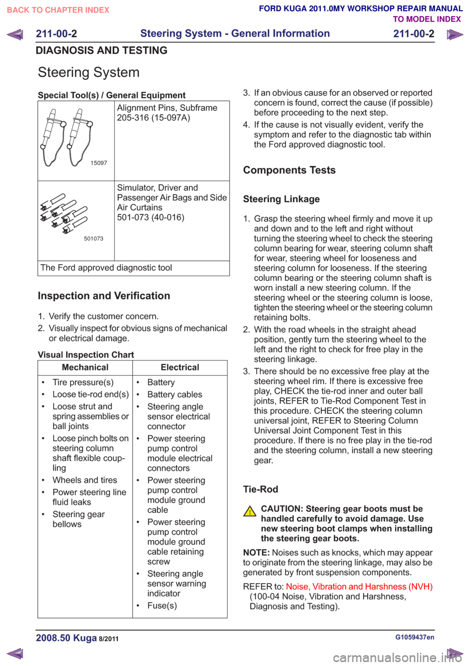
Special Tool(s) / General EquipmentAlignment Pins, Subframe
205-316 (15-097A)
15097
Simulator, Driver and
Passenger Air Bags and Side
Air Curtains
501-073 (40-016)
501073
The Ford approved diagnostic tool
Inspection and Verification
1. Verify the customer concern.
2. Visually inspect for obvious signs of mechanicalor electrical damage.
Visual Inspection Chart
Electrical
Mechanical
• Battery
• Battery cables
• Steering anglesensor electrical
connector
• Power steering pump control
module electrical
connectors
• Power steering pump control
module ground
cable
• Power steering pump control
module ground
cable retaining
screw
• Steering angle sensor warning
indicator
• Fuse(s)
• Tire pressure(s)
• Loose tie-rod end(s)
• Loose strut and
spring assemblies or
ball joints
• Loose pinch bolts on steering column
shaft flexible coup-
ling
• Wheels and tires
• Power steering line fluid leaks
• Steering gear bellows 3. If an obvious cause for an observed or reported
concern is found, correct the cause (if possible)
before proceeding to the next step.
4. If the cause is not visually evident, verify the symptom and refer to the diagnostic tab within
the Ford approved diagnostic tool.
Components Tests
Steering Linkage
1. Grasp the steering wheel firmly and move it upand down and to the left and right without
turning the steering wheel to check the steering
column bearing for wear, steering column shaft
for wear, steering wheel for looseness and
steering column for looseness. If the steering
column bearing or the steering column shaft is
worn install a new steering column. If the
steering wheel or the steering column is loose,
tighten the steering wheel or the steering column
retaining bolts.
2. With the road wheels in the straight ahead position, gently turn the steering wheel to the
left and the right to check for free play in the
steering linkage.
3. There should be no excessive free play at the steering wheel rim. If there is excessive free
play, CHECK the tie-rod inner and outer ball
joints, REFER to Tie-Rod Component Test in
this procedure. CHECK the steering column
universal joint, REFER to Steering Column
Universal Joint Component Test in this
procedure. If there is no free play in the tie-rod
and the steering column, install a new steering
gear.
Tie-Rod
CAUTION: Steering gear boots must be
handled carefully to avoid damage. Use
new steering boot clamps when installing
the steering gear boots.
NOTE: Noises such as knocks, which may appear
to originate from the steering linkage, may also be
generated by front suspension components.
REFER to: Noise, Vibration and Harshness (NVH)
(100-04 Noise, Vibration and Harshness,
Diagnosis and Testing).
G1059437en2008.50 Kuga8/2011
211-00- 2
Steering System - General Information
211-00- 2
DIAGNOSIS AND TESTING
TO MODEL INDEX
BACK TO CHAPTER INDEX
FORD KUGA 2011.0MY WORKSHOP REPAIR MANUAL
Page 1444 of 2057
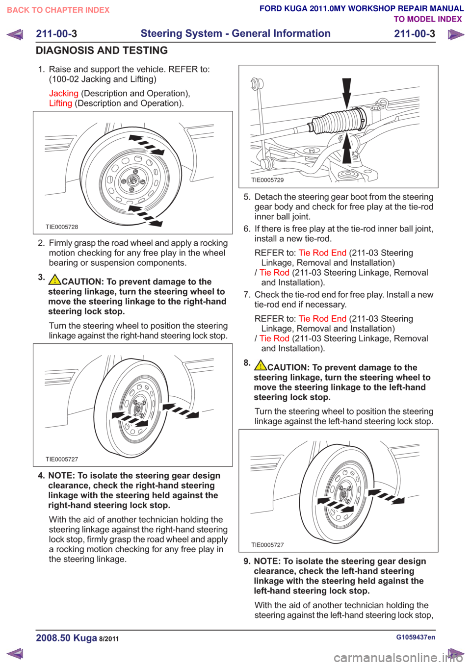
1. Raise and support the vehicle. REFER to:(100-02 Jacking and Lifting)
Jacking (Description and Operation),
Lifting (Description and Operation).
TIE0005728
2. Firmly grasp the road wheel and apply a rocking
motion checking for any free play in the wheel
bearing or suspension components.
3.
CAUTION: To prevent damage to the
steering linkage, turn the steering wheel to
move the steering linkage to the right-hand
steering lock stop.
Turn the steering wheel to position the steering
linkage against the right-hand steering lock stop.
TIE0005727
4. NOTE: To isolate the steering gear design clearance, check the right-hand steering
linkage with the steering held against the
right-hand steering lock stop.
With the aid of another technician holding the
steering linkage against the right-hand steering
lock stop, firmly grasp the road wheel and apply
a rocking motion checking for any free play in
the steering linkage.
TIE0005729
5. Detach the steering gear boot from the steering gear body and check for free play at the tie-rod
inner ball joint.
6. If there is free play at the tie-rod inner ball joint, install a new tie-rod.
REFER to: Tie Rod End (211-03 Steering
Linkage, Removal and Installation)
/ Tie Rod (211-03 Steering Linkage, Removal
and Installation).
7. Check the tie-rod end for free play. Install a new tie-rod end if necessary.
REFER to: Tie Rod End (211-03 Steering
Linkage, Removal and Installation)
/ Tie Rod (211-03 Steering Linkage, Removal
and Installation).
8.
CAUTION: To prevent damage to the
steering linkage, turn the steering wheel to
move the steering linkage to the left-hand
steering lock stop.
Turn the steering wheel to position the steering
linkage against the left-hand steering lock stop.
TIE0005727
9. NOTE: To isolate the steering gear design clearance, check the left-hand steering
linkage with the steering held against the
left-hand steering lock stop.
With the aid of another technician holding the
steering against the left-hand steering lock stop,
G1059437en2008.50 Kuga8/2011
211-00- 3
Steering System - General Information
211-00- 3
DIAGNOSIS AND TESTING
TO MODEL INDEX
BACK TO CHAPTER INDEX
FORD KUGA 2011.0MY WORKSHOP REPAIR MANUAL