Page 1979 of 2057

Fuel Tank Draining
General EquipmentFluid Container
Fuel Tank Draining Equipment
Hose Clamp Remover/Installer
Activation
CAUTION: If the fuel tank has been filled
with the wrong type of fuel, the engine
must not be started.
NOTE: Removal steps in this procedure may
contain installation details.
6. Refer to: Petrol and Petrol-Ethanol Fuel
Systems Health and Safety Precautions
(100-00 General Information, Description and
Operation).
7. Refer to: Lifting(100-02 Jacking and Lifting,
Description and Operation).
8. WARNINGS:
Fuel may still be present in the fuel tank
after draining.
Be prepared to collect escaping fluids.
CAUTION: Use suitable paper to absorb
any escaping fluid. NOTE:
Make sure that a new component is
installed.
• General Equipment: Hose Clamp Remover/Installer
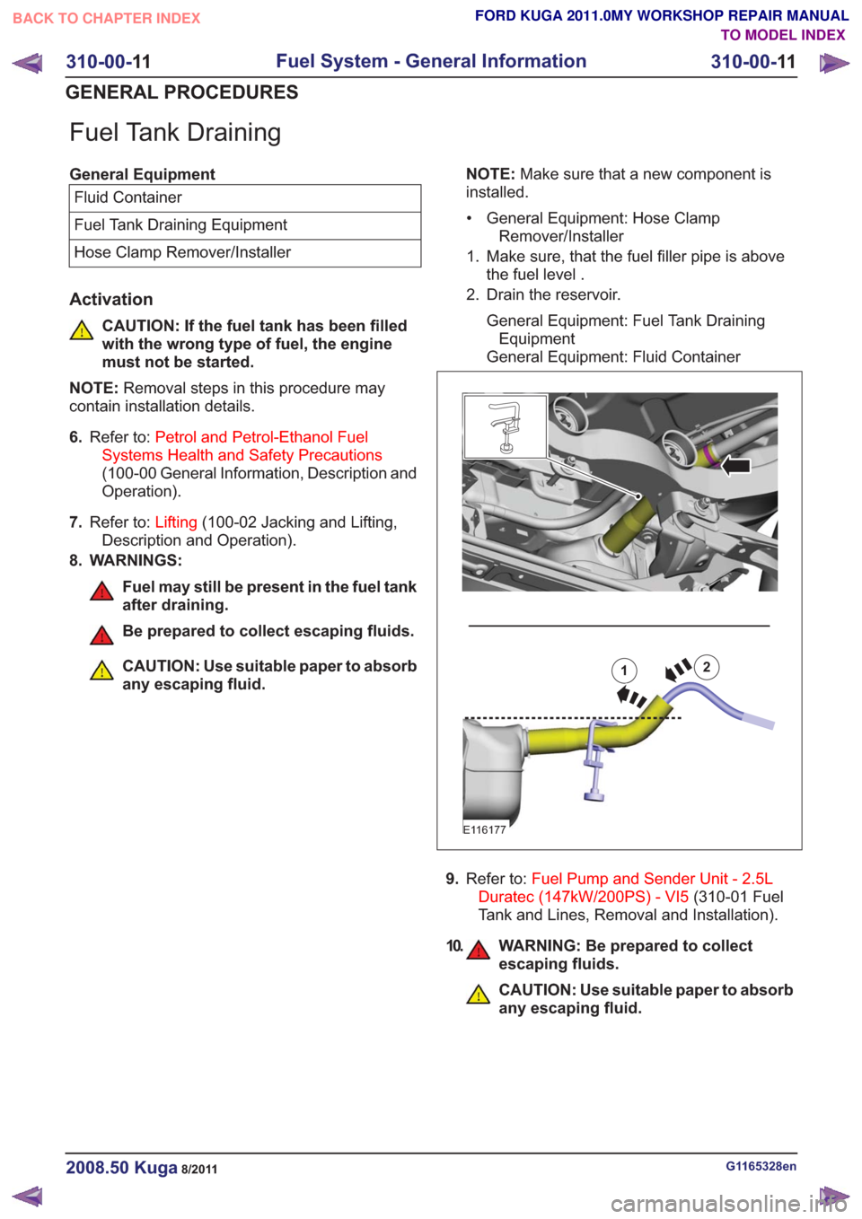
1. Make sure, that the fuel filler pipe is above the fuel level .
2. Drain the reservoir.
General Equipment: Fuel Tank DrainingEquipment
General Equipment: Fluid Container12
E116177
9. Refer to: Fuel Pump and Sender Unit - 2.5L
Duratec (147kW/200PS) - VI5 (310-01 Fuel
Tank and Lines, Removal and Installation).
10. WARNING: Be prepared to collect escaping fluids.
CAUTION: Use suitable paper to absorb
any escaping fluid.
G1165328en2008.50 Kuga8/2011
310-00- 11
Fuel System - General Information
310-00- 11
GENERAL PROCEDURES
TO MODEL INDEX
BACK TO CHAPTER INDEX
FORD KUGA 2011.0MY WORKSHOP REPAIR MANUAL
Page 1981 of 2057

SECTION 310-01 Fuel Tank and Lines
VEHICLE APPLICATION:2008.50 Kuga
PA G E
CONTENTS
DESCRIPTION AND OPERATION
310-01-2
Fuel Tank and Lines — 2.5L Duratec (147kW/200PS) - VI5 (Component Location) .........
310-01-5
Fuel Tank and Lines — 2.5L Duratec (147kW/200PS) - VI5 (Overview) ............................
310-01-5
Fuel tank ........................................................................\
.....................................................
310-01-5
Fuel pump and sender unit ........................................................................\
.........................
310-01-6
Fuel filler pipe and tank cap........................................................................\
........................
REMOVAL AND INSTALLATION 310-01-8
Fuel Tank — 2.5L Duratec (147kW/200PS) - VI5 ...............................................................
310-01-11
Fuel Level Sensor — 2.5L Duratec (147kW/200PS) - VI5 .................................................
310-01-12
Fuel Tank Filler Pipe ........................................................................\
...................................
310-01-14
Fuel Filler Nozzle Inhibitor ........................................................................\
..........................
310-01-18
Fuel Pump and Sender Unit — 2.5L Duratec (147kW/200PS) - VI5 ..................................
310-01-1
Fuel Tank and Lines
310-01- 1
.
TO MODEL INDEX
BACK TO CHAPTER INDEX
FORD KUGA 2011.0MY WORKSHOP REPAIR MANUAL
Page 1982 of 2057
Fuel Tank and Lines — 2.5L Duratec (147kW/200PS) - VI5 –Component Location
E105870
1
2
3
4
5
6
7
8
10
9
11
Description
Item
Fuel pump and level indicator module,
right-hand side
1
EVAP (evaporative emission) extraction
points
2
Fuel pump and lines for the fuel-fired
booster heater/additional heater
3Description
Item
Fuel-filler pipe
4
EVAP container and lines
5
Vent hose, fuel filler pipe
6
Fuel pump and level indicator module,
left-hand side
7
Fuel tank
8
G1079157en2008.50 Kuga8/2011
310-01- 2
Fuel Tank and Lines
310-01- 2
DESCRIPTION AND OPERATION
TO MODEL INDEX
BACK TO CHAPTER INDEX
FORD KUGA 2011.0MY WORKSHOP REPAIR MANUAL
Page 1985 of 2057
Fuel Tank and Lines — 2.5L Duratec (147kW/200PS) - VI5 –Overview
Fuel tank
The fuel tank is the same on vehicles with FWD
and AWD. The fuel tank is saddle-shaped to accommodate the drive shaft and the exhaust
system. Depending on the design, the volume of
the tank is 56 liters or 66 liters.
Fuel pump and sender unit
E106247
12
Description
Item
Fuel pump and level indicator module,
left-hand side
Comments:Inactive side without separate fuel pump
1
Fuel pump and level indicator module,
right-hand side
2
G1090887en2008.50 Kuga8/2011
310-01-
5
Fuel Tank and Lines
310-01- 5
DESCRIPTION AND OPERATION
TO MODEL INDEX
BACK TO CHAPTER INDEX
FORD KUGA 2011.0MY WORKSHOP REPAIR MANUAL
Page 1988 of 2057
Fuel Tank — 2.5L Duratec (147kW/200PS) - VI5
Removal
WARNING: Avoid flames, sparks or lighted
substances.
NOTE: Removal steps in this procedure may
contain installation details.
1. Refer to: Battery Disconnect and Connect
(414-01 Battery, Mounting and Cables,
General Procedures).
4x4
2. Refer to: Driveshaft (205-01 Driveshaft,
Removal and Installation).
All vehicles
3. Torque: 48Nm
x2x2
E104225
4.
E104226
5.Torque: 15Nm
E113922
x2
6.Torque: 15Nm
x4x4
E113923
G1175018en2008.50 Kuga8/2011
310-01- 8
Fuel Tank and Lines
310-01- 8
REMOVAL AND INSTALLATION
TO MODEL INDEX
BACK TO CHAPTER INDEX
FORD KUGA 2011.0MY WORKSHOP REPAIR MANUAL
Page 1990 of 2057
14.
E104859
x2
15. WARNING: Be prepared to collectescaping fluids.
CAUTION: Use suitable paper to absorb
any escaping fluid.
x2x2
E113946
16.
E104642
x2
Vehicles with fuel fired booster heater
NOTE:This step is only necessary when installing
a new component.
17. WARNING: Be prepared to collect escaping fluids.
CAUTION: Use suitable paper to absorb
any escaping fluid.
Refer to: Quick Release Coupling (310-00 Fuel
System - General Information, General
Procedures).
E113927
All vehicles
NOTE: This step is only necessary when installing
a new component.
18. Refer to: Fuel Pump and Sender Unit - 2.5L
Duratec (147kW/200PS) - VI5 (310-01 Fuel
Tank and Lines, Removal and Installation).
Installation
1. To install, reverse the removal procedure.
G1175018en2008.50 Kuga8/2011
310-01- 10
Fuel Tank and Lines
310-01- 10
REMOVAL AND INSTALLATION
TO MODEL INDEX
BACK TO CHAPTER INDEX
FORD KUGA 2011.0MY WORKSHOP REPAIR MANUAL
Page 1991 of 2057
Fuel Level Sensor — 2.5L Duratec (147kW/200PS) - VI5
Removal
1.Refer to: Fuel Pump and Sender Unit - 2.5L
Duratec (147kW/200PS) - VI5 (310-01 Fuel
Tank and Lines, Removal and Installation).
Installation
1. To install, reverse the removal procedure.
G1000788en2008.50 Kuga8/2011
310-01- 11
Fuel Tank and Lines
310-01- 11
REMOVAL AND INSTALLATION
TO MODEL INDEX
BACK TO CHAPTER INDEX
FORD KUGA 2011.0MY WORKSHOP REPAIR MANUAL
Page 1998 of 2057
Fuel Pump and Sender Unit — 2.5L Duratec (147kW/200PS) -VI5
Special Tool(s) / General Equipment
310-210
Wrench, Fuel Tank Sender
Unit
E115757
Special Tool(s) / General Equipment310-211
Wrench, Fuel Tank Sender
Unit
E115758
Fluid Container
Removal
NOTE:Removal steps in this procedure may
contain installation details.
1. Refer to: Fuel Tank - 2.5L Duratec
(147kW/200PS) - VI5 (310-01 Fuel Tank and
Lines, Removal and Installation).
2. Special Tool(s): 310-211
Torque: 1
10Nm
310-211
x2
310-211
x2
E114253
3. CAUTION: Take extra care not to
damage the fuel tank level sensor float
and arm.
E112921
4.
E112922
Vehicles without fuel fired booster heater
5.Refer to: Quick Release Coupling (310-00 Fuel
System - General Information, General
Procedures).
E116270
G1000791en2008.50 Kuga8/2011
310-01- 18
Fuel Tank and Lines
310-01- 18
REMOVAL AND INSTALLATION
TO MODEL INDEX
BACK TO CHAPTER INDEX
FORD KUGA 2011.0MY WORKSHOP REPAIR MANUAL