2011 FORD KUGA oil
[x] Cancel search: oilPage 190 of 2057

Instrument Cluster
Refer to
Wiring Diagrams Section 413-01, for
schematic and connector information. General Equipment
The Ford approved diagnostic tool
Inspection and Verification
1. Verify the customer concern.
2. Visually inspect for obvious signs of mechanical
or electrical damage.
Visual Inspection Chart Electrical
Mechanical
– Fuse(s)
– Wiring harness
– Electricalconnector(s)
– Instrument cluster
– Light emitting diode(s) (LED)(s)
– Engine oil filter
– Engine oil level
–
Engine coolant level
– Oil pressure switch
– Engine coolant level
– Coolant thermostat
– Engine coolant temperature (ECT)
sensor
– Fuel gauge
– Collapsed or damaged fuel tank
– Recirculation hose
– Fuel tank filler pipe/hose
– Indicated fuel level
– Fuel lines
– Fuel tank filler cap
– Fuel filter (external to the fuel tank)
– Fuel tank
– Door adjustment
3. If an obvious cause for an observed or reported concern is found, correct the cause (if possible)
before proceeding to the next step.
4. NOTE: If none of the following warning indicators are operating correctly this may
indicate a concern with the central junction
box (CJB). If only one or two of the following
warning indicators are not operating
correctly this may indicate an instrument
cluster concern. Verify the following warning indicators are
working correctly:
• Charging.
• Turn signals.
• Headlamps.
5. If the cause is not visually evident, verify the symptom and refer to the diagnostic tab within
the Ford approved diagnostic tool.
Configuration of the Instrument Cluster
The instrument cluster is a programmable module,
which must be configured by selecting the
Programmable Module Installation Routine on the
Ford approved diagnostic tool.
NOTE: When the new instrument cluster has been
configured with the odometer value, its
configuration cannot be decreased or matched. A
new configuration will result in an increase in the
displayed odometer value by a minimum of two
units.
NOTE: The odometer value must be recorded from
the original instrument cluster before removal.
If the odometer value cannot be obtained from
the original instrument cluster (display failure)
the customer should supply the approximate
value.
The following features will need to be configured
when a new instrument cluster is installed:
• Anti-lock Brake System (ABS)
• All wheel drive
• Keyless vehicle entry
• Electronic power assisted steering
• Trip computer
• Voice control
• Parking aid
• Belt minder
• Safety belt not fastened
• Right hand drive
• Overspeed warning
• Reverse warning
• Turbocharger boost pressure
• Speed control
• Auxiliary heater
• Suspension control
• Washer fluid sensor G1054964en
2008.50 Kuga 8/2011 413-01-7
Instrument Cluster
413-01-7
DIAGNOSIS AND TESTINGTO MODEL INDEX
BACK TO CHAPTER INDEX
FORD KUGA 2011.0MY WORKSHOP REPAIR MANUAL
Page 196 of 2057

SECTION 413-09 Warning Devices
VEHICLE APPLICATION:
2008.50 Kuga
PAGE
CONTENTS
DIAGNOSIS AND TESTING
413-09-2
Warning Devices.................................................................................................................
413-09-2
Inspection and Verification..................................................................................................
GENERAL PROCEDURES 413-09-3
Safety Belt Minder Deactivating/Activating.........................................................................
413-09-3
Preparation .........................................................................................................................
413-09-3
Deactivating/Activating .......................................................................................................
413-09-4
Oil Change Indicator Reset................................................................................................ 413-09-1
Warning Devices
413-09-1
.TO MODEL INDEX
BACK TO CHAPTER INDEX
FORD KUGA 2011.0MY WORKSHOP REPAIR MANUAL
Page 199 of 2057

Oil Change Indicator Reset
1.
Turn the ignition key to position II without
cranking the engine.
2. Simultaneously press and hold the accelerator
pedal and the brake pedal for approximately 15
seconds until the oil change reminder indicator
starts to flash or the "Service Oil Reset
Complete" message appears in the information
and message center (if equipped).
3. Release the pedals.
4. Check that the oil change reminder indicator
has turned off or that there is no "Service Oil"
message in the information and message center
(if equipped). If the oil change reminder indicator
is still illuminated or the "Service Oil" message
is still displayed, turn the ignition key to position
0 and repeat the procedure from Step 1. If it has
turned off or the "Service Oil" message has
disappeared, proceed to Step 5.
5. Turn the ignition key to position 0 and leave it
there for at least 2 minutes so that the
powertrain control module (PCM) fully powers
down and updates the non-volatile memory
(NVM) in the PCM.
6. Turn the ignition key to position II without
cranking the engine and check that the oil
change reminder indicator is not illuminated or
that there is no "Service Oil" message displayed.
7. Turn the ignition key to position 0. G898940en
2008.50 Kuga 8/2011 413-09-4
Warning Devices
413-09-4
GENERAL PROCEDURESTO MODEL INDEX
BACK TO CHAPTER INDEX
FORD KUGA 2011.0MY WORKSHOP REPAIR MANUAL
Page 342 of 2057

On some models, the door entry lamps are installed
in the external mirrors.
The door entry lamps should illuminate the ground
in the immediate vicinity of the front doors; they
are equipped with white bulbs, which are installed
in the underside of the mirror.
The door entry illumination is switched on when
one of the doors or the tailgate are opened, or if
an unlocking command is detected and the
following conditions are satisfied:
• Vehicle Ignition is off.
• Reverse gear is not engaged.
• The vehicle speed is below 7 km/h.
The door entry illumination is switched off if one of
the following conditions is satisfied:
• The ignition is selected on.
• Reverse gear is engaged.
• The vehicle speed exceeds 7 km/h.
• More than 25 seconds have elapsed since the
tailgate was closed or a central locking
command was determined.
• The time set for the battery protection function for the interior lighting has elapsed.
• More than 5 seconds have elapsed since the doors and the tailgate were closed.
• More than 5 seconds have elapsed since a central locking command was received and the
all doors and the tailgate were closed. Rear Lighting The rear lamps are each divided into three units.
The reversing lamps are located in the units in the
liftgate.
The outer units in the D-pillars contain the side
lamp as well as the turn signal and stoplamp.
The rear fog lamp is integrated in the lower area
of the bumper.
The high-mounted additional stop lamp is installed
in the middle of the roof spoiler.
Bulb color
Current draw
Bulb
Lamp
Orange
19W
PSY19W
Turn signal indicator
Clear
21W
P21W
Reversing Lamp
Clear
21/5W
W21/5W
Stoplamp/side lamp
Clear
21W
P21W
Rear fog lamp
–
1,4W
1 x LED board
Additional high-mounted
stoplamp G1079626en
2008.50 Kuga 8/2011 417-01-8
Exterior Lighting
417-01-8
DESCRIPTION AND OPERATIONTO MODEL INDEX
BACK TO CHAPTER INDEX
FORD KUGA 2011.0MY WORKSHOP REPAIR MANUALE101618
Page 1164 of 2057

DETAILS/RESULTS/ACTIONS
TEST CONDITIONS
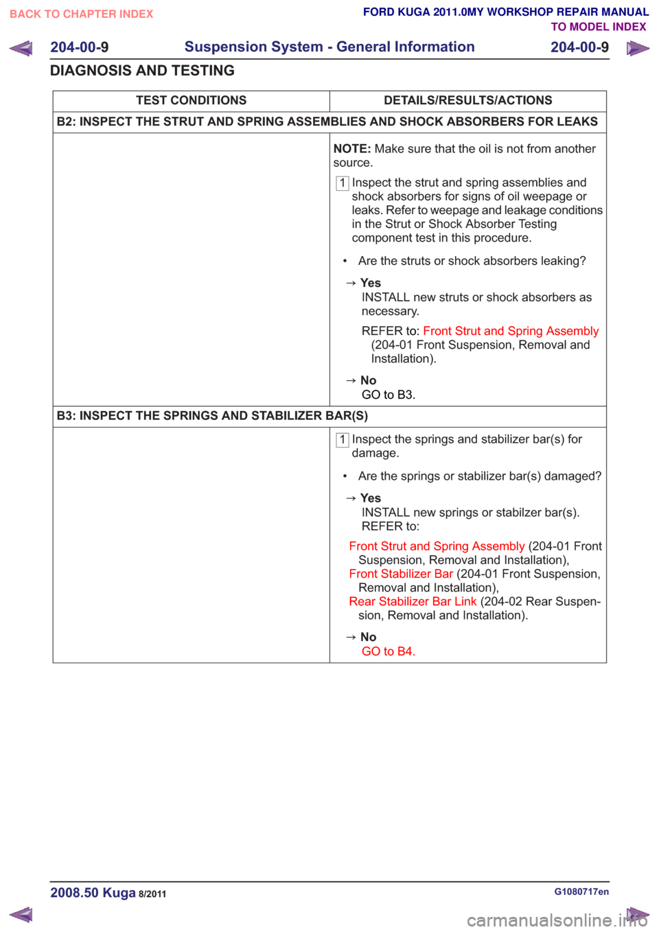
B2: INSPECT THE STRUT AND SPRING ASSEMBLIES AND SHOCK ABSORBERS FOR LEAKS
NOTE:Make sure that the oil is not from another
source.
1 Inspect the strut and spring assemblies and
shock absorbers for signs of oil weepage or
leaks. Refer to weepage and leakage conditions
in the Strut or Shock Absorber Testing
component test in this procedure.
• Are the struts or shock absorbers leaking?
zYe s INSTALL new struts or shock absorbers as
necessary.
REFER to: Front Strut and Spring Assembly
(204-01 Front Suspension, Removal and
Installation).
zNo
GO to B3.
B3: INSPECT THE SPRINGS AND STABILIZER BAR(S)
1 Inspect the springs and stabilizer bar(s) for
damage.
• Are the springs or stabilizer bar(s) damaged?
zYe s INSTALL new springs or stabilzer bar(s).
REFER to:
Front Strut andSpring Assembly (204-01 Front
Suspension, Removal and Installation),
Front Stabilizer Bar (204-01 Front Suspension,
Removal and Installation),
Rear Stabilizer Bar Link (204-02 Rear Suspen-
sion, Removal and Installation).
zNo
GO to B4.
G1080717en2008.50 Kuga8/2011
204-00- 9
Suspension System - General Information
204-00- 9
DIAGNOSIS AND TESTING
TO MODEL INDEX
BACK TO CHAPTER INDEX
FORD KUGA 2011.0MY WORKSHOP REPAIR MANUAL
Page 1168 of 2057

3. If a new lower arm is installed it will benecessary to check and adjust the front wheel
alignment.
REFER to: Front Toe Adjustment (204-00
Suspension System - General Information,
General Procedures)
/ Rear Toe Adjustment (204-00 Suspension
System - General Information, General
Procedures).
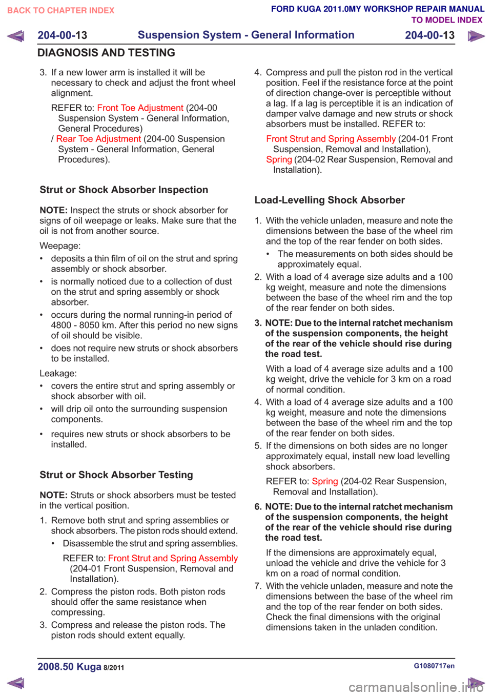
Strut or Shock Absorber Inspection
NOTE: Inspect the struts or shock absorber for
signs of oil weepage or leaks. Make sure that the
oil is not from another source.
Weepage:
• deposits a thin film of oil on the strut and spring assembly or shock absorber.
• is normally noticed due to a collection of dust on the strut and spring assembly or shock
absorber.
• occurs during the normal running-in period of 4800 - 8050 km. After this period no new signs
of oil should be visible.
• does not require new struts or shock absorbers to be installed.
Leakage:
• covers the entire strut and spring assembly or shock absorber with oil.
• will drip oil onto the surrounding suspension components.
• requires new struts or shock absorbers to be installed.
Strut or Shock Absorber Testing
NOTE: Struts or shock absorbers must be tested
in the vertical position.
1. Remove both strut and spring assemblies or shock absorbers. The piston rods should extend.
• Disassemble the strut and spring assemblies.
REFER to: Front Strut and Spring Assembly
(204-01 Front Suspension, Removal and
Installation).
2. Compress the piston rods. Both piston rods should offer the same resistance when
compressing.
3. Compress and release the piston rods. The piston rods should extent equally. 4. Compress and pull the piston rod in the vertical
position. Feel if the resistance force at the point
of direction change-over is perceptible without
a lag. If a lag is perceptible it is an indication of
damper valve damage and new struts or shock
absorbers must be installed. REFER to:
Front Strut and Spring Assembly (204-01 Front
Suspension, Removal and Installation),
Spring (204-02 Rear Suspension, Removal and
Installation).
Load-Levelling Shock Absorber
1. With the vehicle unladen, measure and note the dimensions between the base of the wheel rim
and the top of the rear fender on both sides.
• The measurements on both sides should be approximately equal.
2. With a load of 4 average size adults and a 100 kg weight, measure and note the dimensions
between the base of the wheel rim and the top
of the rear fender on both sides.
3. NOTE: Due to the internal ratchet mechanism of the suspension components, the height
of the rear of the vehicle should rise during
the road test.
With a load of 4 average size adults and a 100
kg weight, drive the vehicle for 3 km on a road
of normal condition.
4. With a load of 4 average size adults and a 100 kg weight, measure and note the dimensions
between the base of the wheel rim and the top
of the rear fender on both sides.
5. If the dimensions on both sides are no longer approximately equal, install new load levelling
shock absorbers.
REFER to: Spring(204-02 Rear Suspension,
Removal and Installation).
6. NOTE: Due to the internal ratchet mechanism of the suspension components, the height
of the rear of the vehicle should rise during
the road test.
If the dimensions are approximately equal,
unload the vehicle and drive the vehicle for 3
km on a road of normal condition.
7. With the vehicle unladen, measure and note the dimensions between the base of the wheel rim
and the top of the rear fender on both sides.
Check the final dimensions with the original
dimensions taken in the unladen condition.
G1080717en2008.50 Kuga8/2011
204-00- 13
Suspension System - General Information
204-00- 13
DIAGNOSIS AND TESTING
TO MODEL INDEX
BACK TO CHAPTER INDEX
FORD KUGA 2011.0MY WORKSHOP REPAIR MANUAL
Page 1200 of 2057

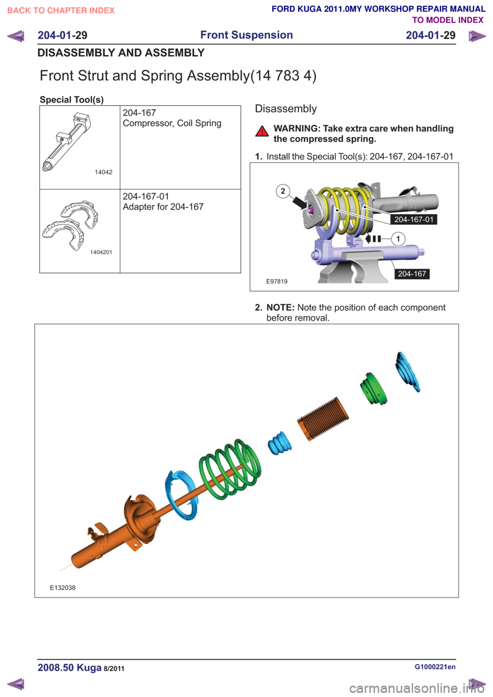
Front Strut and Spring Assembly(14 783 4)
Special Tool(s)204-167
Compressor, Coil Spring
14042
204-167-01
Adapter for 204-167
1404201
Disassembly
WARNING: Take extra care when handling
the compressed spring.
1. Install the Special Tool(s): 204-167, 204-167-01
E97819
204-167-01
204-167
1
2
2. NOTE: Note the position of each component
before removal.
E132038
G1000221en2008.50 Kuga8/2011
204-01- 29
Front Suspension
204-01- 29
DISASSEMBLY AND ASSEMBLY
TO MODEL INDEX
BACK TO CHAPTER INDEX
FORD KUGA 2011.0MY WORKSHOP REPAIR MANUAL
Page 1227 of 2057

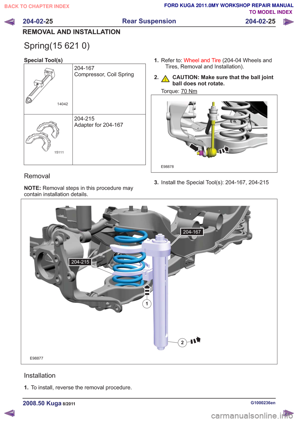
Spring(15 621 0)
Special Tool(s)204-167
Compressor, Coil Spring
14042
204-215
Adapter for 204-167
15111
Removal
NOTE:Removal steps in this procedure may
contain installation details. 1.
Refer to: Wheel and Tire (204-04 Wheels and
Tires, Removal and Installation).
2. CAUTION: Make sure that the ball joint ball does not rotate.
Torque: 70Nm
E98878
3.Install the Special Tool(s): 204-167, 204-215
E98877
1
2
204-167
204-215
Installation
1.To install, reverse the removal procedure.
G1000236en2008.50 Kuga8/2011
204-02- 25
Rear Suspension
204-02- 25
REMOVAL AND INSTALLATION
TO MODEL INDEX
BACK TO CHAPTER INDEX
FORD KUGA 2011.0MY WORKSHOP REPAIR MANUAL