Page 1438 of 2057
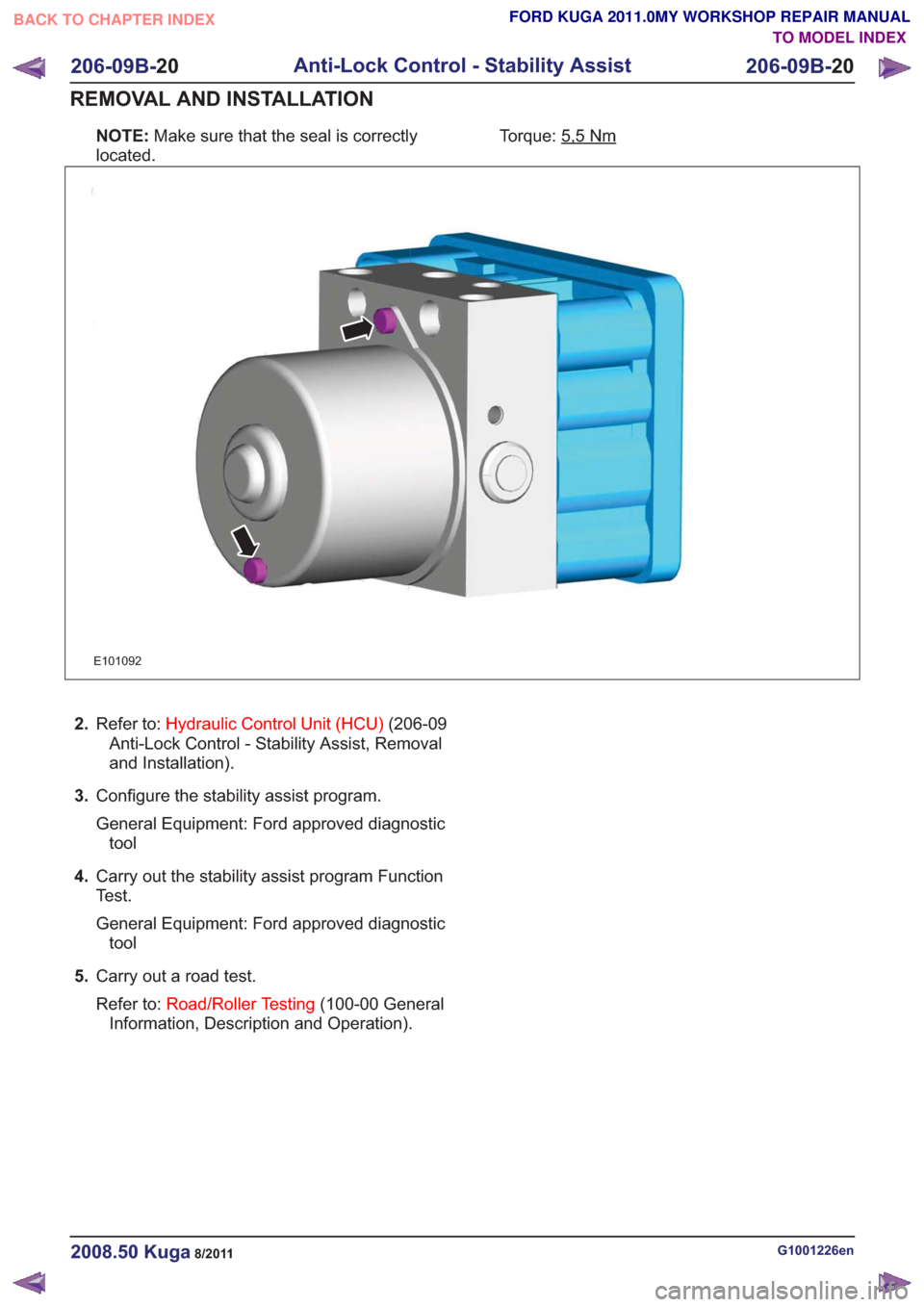
NOTE:Make sure that the seal is correctly
located. Torque: 5,5Nm
E101092
2.
Refer to: Hydraulic Control Unit (HCU) (206-09
Anti-Lock Control - Stability Assist, Removal
and Installation).
3. Configure the stability assist program.
General Equipment: Ford approved diagnostic
tool
4. Carry out the stability assist program Function
Test.
General Equipment: Ford approved diagnostic
tool
5. Carry out a road test.
Refer to: Road/Roller Testing (100-00 General
Information, Description and Operation).
G1001226en2008.50 Kuga8/2011
206-09B- 20
Anti-Lock Control - Stability Assist
206-09B- 20
REMOVAL AND INSTALLATION
TO MODEL INDEX
BACK TO CHAPTER INDEX
FORD KUGA 2011.0MY WORKSHOP REPAIR MANUAL
Page 1439 of 2057
Front Wheel Speed Sensor
Removal
NOTE:Removal steps in this procedure may
contain installation details.
1. Refer to: Wheel and Tire (204-04 Wheels and
Tires, Removal and Installation).
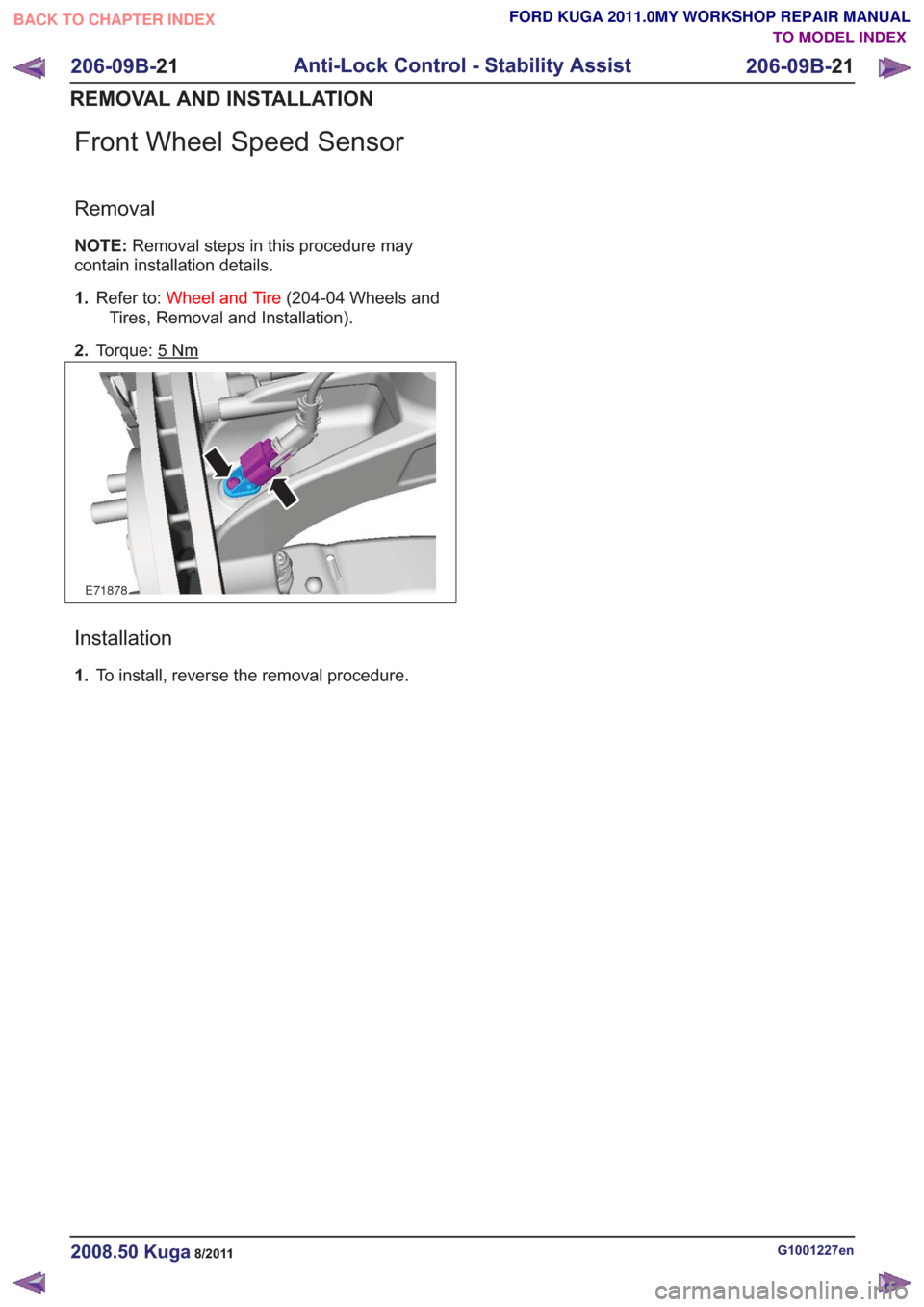
2. Torque: 5
Nm
E71878
Installation
1.To install, reverse the removal procedure.
G1001227en2008.50 Kuga8/2011
206-09B- 21
Anti-Lock Control - Stability Assist
206-09B- 21
REMOVAL AND INSTALLATION
TO MODEL INDEX
BACK TO CHAPTER INDEX
FORD KUGA 2011.0MY WORKSHOP REPAIR MANUAL
Page 1440 of 2057
Rear Wheel Speed Sensor
Removal
NOTE:Removal steps in this procedure may
contain installation details.
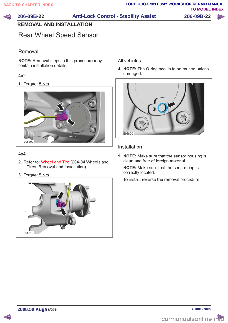
4x2
1. Torque: 5Nm
E98809
4x4
2.Refer to: Wheel and Tire (204-04 Wheels and
Tires, Removal and Installation).
3. Torque: 5
Nm
E98810
All vehicles
4. NOTE: The O-ring seal is to be reused unless
damaged.
E98820
Installation
1. NOTE: Make sure that the sensor housing is
clean and free of foreign material.
NOTE: Make sure that the sensor ring is
correctly located.
To install, reverse the removal procedure.
G1001228en2008.50 Kuga8/2011
206-09B- 22
Anti-Lock Control - Stability Assist
206-09B- 22
REMOVAL AND INSTALLATION
TO MODEL INDEX
BACK TO CHAPTER INDEX
FORD KUGA 2011.0MY WORKSHOP REPAIR MANUAL
Page 1441 of 2057
Yaw Rate Sensor
Removal
NOTE:Removal steps in this procedure may
contain installation details.
1. Refer to: Front Seat (501-10 Seating, Removal
and Installation).
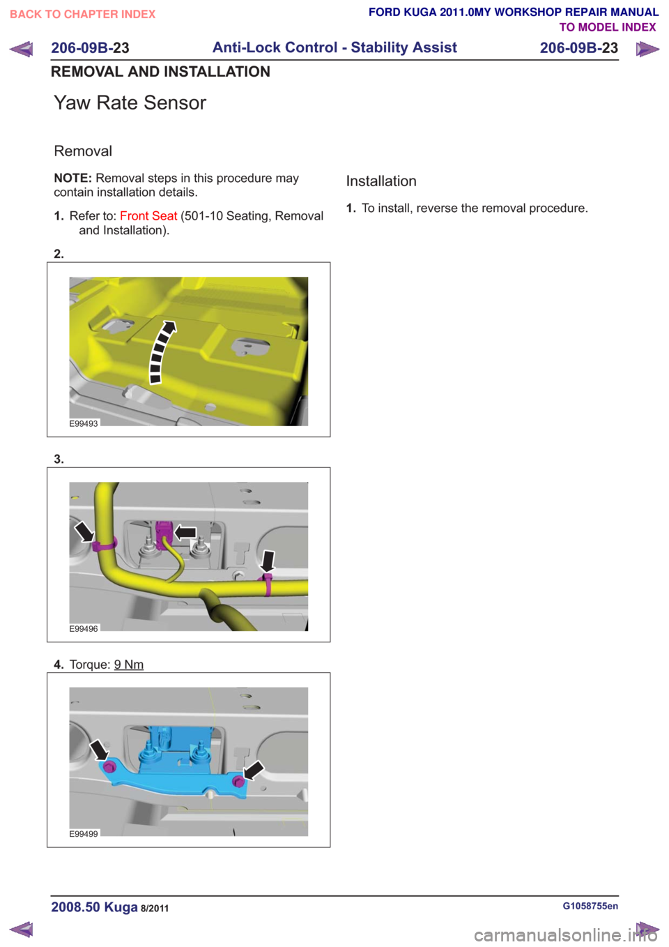
2.
E99493
3.
E99496
4. Torque: 9Nm
E99499
Installation
1.To install, reverse the removal procedure.
G1058755en2008.50 Kuga8/2011
206-09B- 23
Anti-Lock Control - Stability Assist
206-09B- 23
REMOVAL AND INSTALLATION
TO MODEL INDEX
BACK TO CHAPTER INDEX
FORD KUGA 2011.0MY WORKSHOP REPAIR MANUAL
Page 1511 of 2057
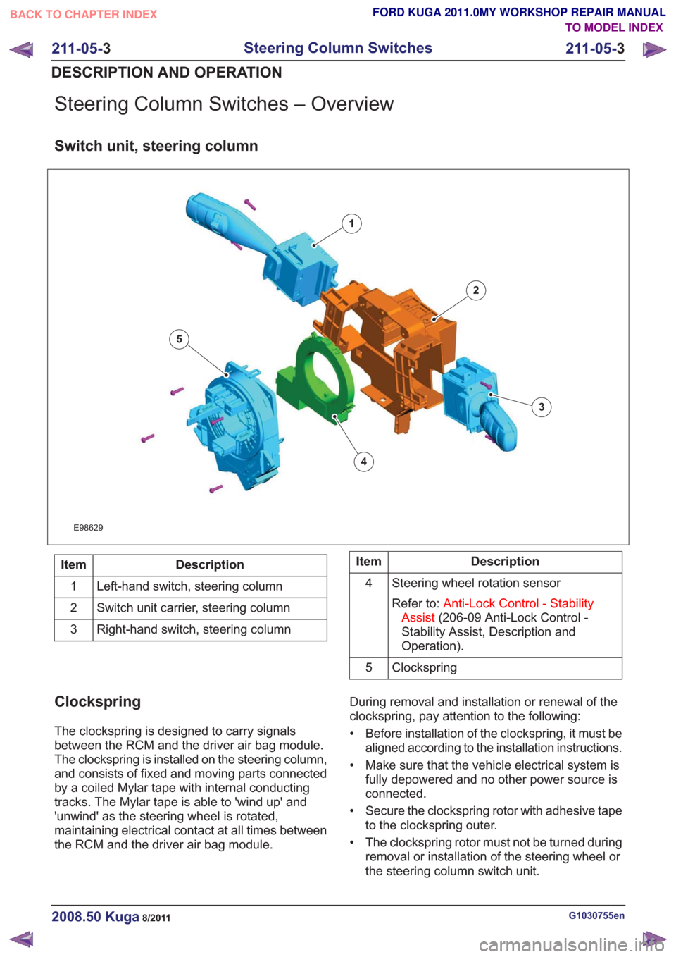
Steering Column Switches – Overview
Switch unit, steering column
E98629
1
2
3
4
5
Description
Item
Left-hand switch, steering column
1
Switch unit carrier, steering column
2
Right-hand switch, steering column
3Description
Item
Steering wheel rotation sensor
Refer to: Anti-Lock Control - Stability
Assist (206-09 Anti-Lock Control -
Stability Assist, Description and
Operation).
4
Clockspring
5
Clockspring
The clockspring is designed to carry signals
between the RCM and the driver air bag module.
The clockspring is installed on the steering column,
and consists of fixed and moving parts connected
by a coiled Mylar tape with internal conducting
tracks. The Mylar tape is able to 'wind up' and
'unwind' as the steering wheel is rotated,
maintaining electrical contact at all times between
the RCM and the driver air bag module. During removal and installation or renewal of the
clockspring, pay attention to the following:
• Before installation of the clockspring, it must be
aligned according to the installation instructions.
• Make sure that the vehicle electrical system is fully depowered and no other power source is
connected.
• Secure the clockspring rotor with adhesive tape to the clockspring outer.
• The clockspring rotor must not be turned during removal or installation of the steering wheel or
the steering column switch unit.
G1030755en2008.50 Kuga8/2011
211-05- 3
Steering Column Switches
211-05- 3
DESCRIPTION AND OPERATION
TO MODEL INDEX
BACK TO CHAPTER INDEX
FORD KUGA 2011.0MY WORKSHOP REPAIR MANUAL