Page 1876 of 2057

Description
Item
Drive
3
Intake side
4
Delivery side
5
The fluid pump operates on the principle of a
G-rotor fluid pump.
The fluid pump draws transmission fluid from the
fluid pan, builds up fluid pressure and then supplies
it to the valve body.
The fluid pump is driven by the crankshaft via the
torque converter housing.
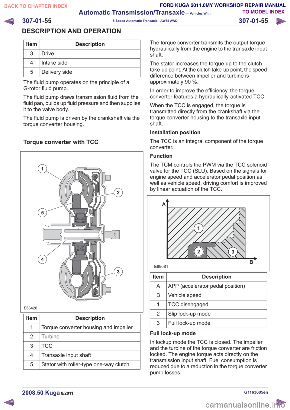
Torque converter with TCC
E66428E66428
1
2
3
5
4
Description
Item
Torque converter housing and impeller
1
Turbine
2
TCC3
Transaxle input shaft
4
Stator with roller-type one-way clutch
5 The torque converter transmits the output torque
hydraulically from the engine to the transaxle input
shaft.
The stator increases the torque up to the clutch
take-up point. At the clutch take-up point, the speed
difference between impeller and turbine is
approximately 90 %.
In order to improve the efficiency, the torque
converter features a hydraulically-activated TCC.
When the TCC is engaged, the torque is
transmitted directly from the crankshaft via the
torque converter housing to the transaxle input
shaft.
Installation position
The TCC is an integral component of the torque
converter.
Function
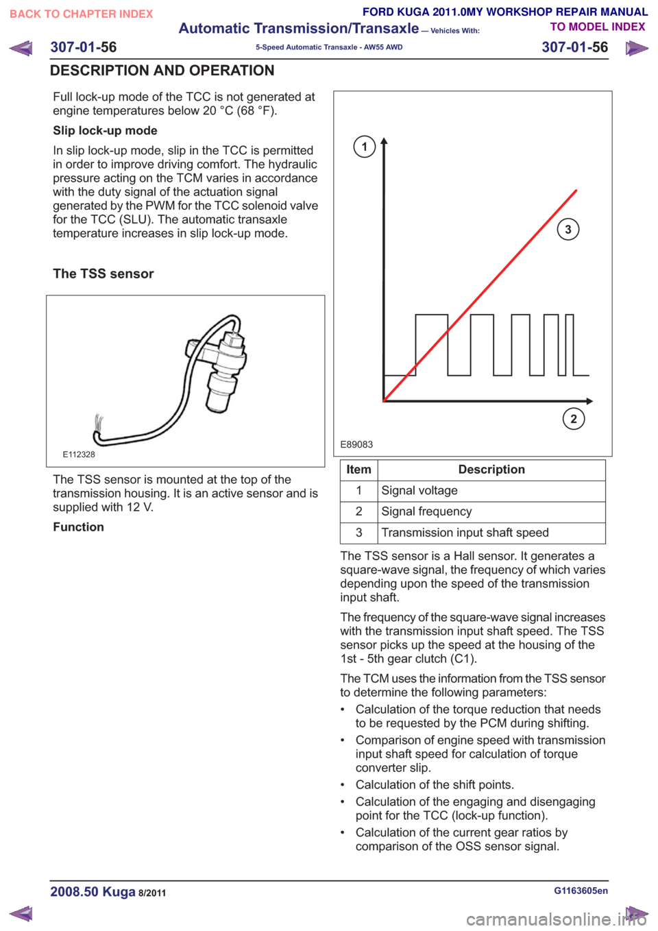
The TCM controls the PWM via the TCC solenoid
valve for the TCC (SLU). Based on the signals for
engine speed and accelerator pedal position as
well as vehicle speed, driving comfort is improved
by linear actuation of the TCC.
E89081
1
A
B
23
Description
Item
APP (accelerator pedal position)
A
Vehicle speed
B
TCC disengaged
1
Slip lock-up mode
2
Full lock-up mode
3
Full lock-up mode
In lockup mode the TCC is closed. The impeller
and the turbine of the torque converter are friction
locked. The engine torque acts directly on the
transmission input shaft. Fuel consumption is
reduced due to a reduction in the torque converter
pump losses.
G1163605en2008.50 Kuga8/2011
307-01- 55
Automatic Transmission/Transaxle
— Vehicles With:
5-Speed Automatic Transaxle - AW55 AWD
307-01- 55
DESCRIPTION AND OPERATION
TO MODEL INDEX
BACK TO CHAPTER INDEX
FORD KUGA 2011.0MY WORKSHOP REPAIR MANUAL
Page 1877 of 2057

Full lock-up mode of the TCC is not generated at
engine temperatures below 20 °C (68 °F).
Slip lock-up mode
In slip lock-up mode, slip in the TCC is permitted
in order to improve driving comfort. The hydraulic
pressure acting on the TCM varies in accordance
with the duty signal of the actuation signal
generated by the PWM for the TCC solenoid valve
for the TCC (SLU). The automatic transaxle
temperature increases in slip lock-up mode.
The TSS sensor
E112328
The TSS sensor is mounted at the top of the
transmission housing. It is an active sensor and is
supplied with 12 V.
Function
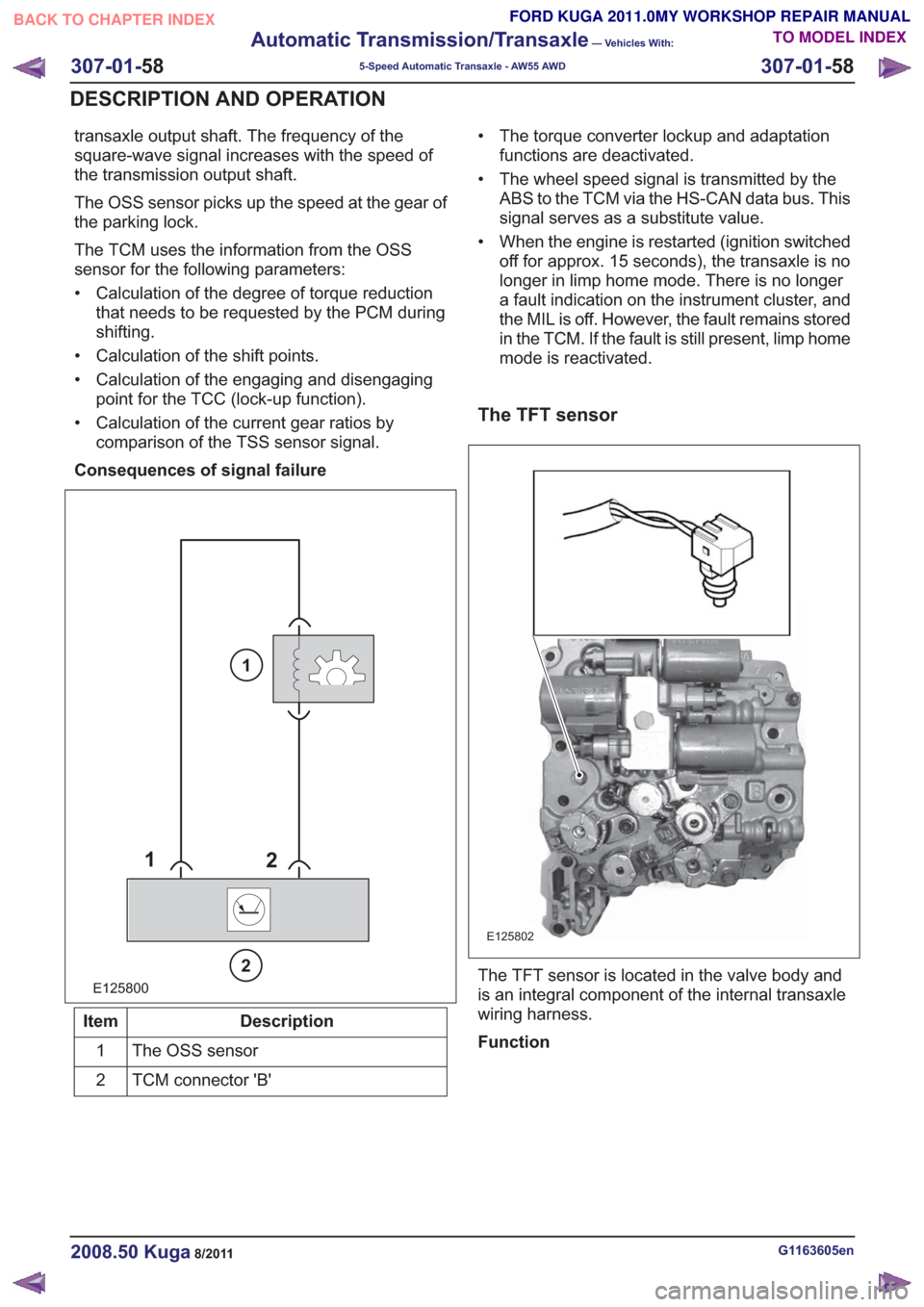
E89083
3
2
1
Description
Item
Signal voltage
1
Signal frequency
2
Transmission input shaft speed
3
The TSS sensor is a Hall sensor. It generates a
square-wave signal, the frequency of which varies
depending upon the speed of the transmission
input shaft.
The frequency of the square-wave signal increases
with the transmission input shaft speed. The TSS
sensor picks up the speed at the housing of the
1st - 5th gear clutch (C1).
The TCM uses the information from the TSS sensor
to determine the following parameters:
• Calculation of the torque reduction that needs to be requested by the PCM during shifting.
• Comparison of engine speed with transmission input shaft speed for calculation of torque
converter slip.
• Calculation of the shift points.
• Calculation of the engaging and disengaging point for the TCC (lock-up function).
• Calculation of the current gear ratios by comparison of the OSS sensor signal.
G1163605en2008.50 Kuga8/2011
307-01- 56
Automatic Transmission/Transaxle
— Vehicles With:
5-Speed Automatic Transaxle - AW55 AWD
307-01- 56
DESCRIPTION AND OPERATION
TO MODEL INDEX
BACK TO CHAPTER INDEX
FORD KUGA 2011.0MY WORKSHOP REPAIR MANUAL
Page 1879 of 2057

transaxle output shaft. The frequency of the
square-wave signal increases with the speed of
the transmission output shaft.
The OSS sensor picks up the speed at the gear of
the parking lock.
The TCM uses the information from the OSS
sensor for the following parameters:
• Calculation of the degree of torque reductionthat needs to be requested by the PCM during
shifting.
• Calculation of the shift points.
• Calculation of the engaging and disengaging point for the TCC (lock-up function).
• Calculation of the current gear ratios by comparison of the TSS sensor signal.
Consequences of signal failure
E125800
1 2
2
1
Description
Item
The OSS sensor
1
TCM connector 'B'
2 • The torque converter lockup and adaptation
functions are deactivated.
• The wheel speed signal is transmitted by the ABS to the TCM via the HS-CAN data bus. This
signal serves as a substitute value.
• When the engine is restarted (ignition switched off for approx. 15 seconds), the transaxle is no
longer in limp home mode. There is no longer
a fault indication on the instrument cluster, and
the MIL is off. However, the fault remains stored
in the TCM. If the fault is still present, limp home
mode is reactivated.
The TFT sensor
E125802
The TFT sensor is located in the valve body and
is an integral component of the internal transaxle
wiring harness.
Function
G1163605en2008.50 Kuga8/2011
307-01- 58
Automatic Transmission/Transaxle
— Vehicles With:
5-Speed Automatic Transaxle - AW55 AWD
307-01- 58
DESCRIPTION AND OPERATION
TO MODEL INDEX
BACK TO CHAPTER INDEX
FORD KUGA 2011.0MY WORKSHOP REPAIR MANUAL
Page 1894 of 2057
Torque Converter Seal
Special Tool(s) / General Equipment303-293
Remover, Crankshaft Seal
21143
Special Tool(s) / General Equipment308-095
Installer, Input Shaft Bearing
16038
Round-Ended Steel Rule
Materials
Specification
Name
WSS-M2C924-A / 4U7J-
M2C924-AA
Automatic Transmission
Oil E-AW
Removal
1.
Refer to: Transmission (307-01 Automatic
Transmission/Transaxle - Vehicles With:
5-Speed Automatic Transaxle - AW55 AWD,
Removal).
2.
E115423
3. Special Tool(s): 303-293
303-293303-293
E115424
G1163637en2008.50 Kuga8/2011
307-01- 73
Automatic Transmission/Transaxle
— Vehicles With:
5-Speed Automatic Transaxle - AW55 AWD
307-01- 73
REMOVAL AND INSTALLATION
TO MODEL INDEX
BACK TO CHAPTER INDEX
FORD KUGA 2011.0MY WORKSHOP REPAIR MANUAL
Page 1913 of 2057
Make sure that the torque converter
remains in the transmission.
General Equipment: Transmission Jack
x2x2
E114751
5. Perform this and the following operation
simultaneously.
Torque: 48
Nm
x2x2
E114623
6.Torque: 48Nm
E114621
7.Remove the following items:
1. General Equipment: Wooden Block General Equipment: Transmission Jack
E114733
8.Torque: 48Nm
E114622
G1163646en2008.50 Kuga8/2011
307-01- 92
Automatic Transmission/Transaxle
— Vehicles With:
5-Speed Automatic Transaxle - AW55 AWD
307-01- 92
INSTALLATION
TO MODEL INDEX
BACK TO CHAPTER INDEX
FORD KUGA 2011.0MY WORKSHOP REPAIR MANUAL
Page 1964 of 2057
Exhaust Flexible Pipe
General EquipmentCable TiesMaterials
Specification
Name
SA-M1C9107-A / YS5J-
M1C9107-AA
Grease KS-PS
Removal
NOTE:
Removal steps in this procedure may
contain installation details.
1.
E65070
2. CAUTION: Make sure that the inside of the pipe ends are clean and free of oil
residue.
1. Torque: 10Nm
2. Torque: 4Nm
3. Torque: 10Nm
2
1
3
E68504
3.Torque: 20Nm
E112607
1
2
34
4.
E67948
2
1
5. CAUTIONS:
Jointing compound must not be used
forward of the catalytic converter.
G1079152en2008.50 Kuga8/2011
309-00- 3
Exhaust System— 2.5L Duratec (147kW/200PS) - VI5309-00-
3
REMOVAL AND INSTALLATION
TO MODEL INDEX
BACK TO CHAPTER INDEX
FORD KUGA 2011.0MY WORKSHOP REPAIR MANUAL
Page 1967 of 2057
Catalytic Converter
General EquipmentCable TiesMaterials
Specification
Name
SA-M1C9107-A / YS5J-
M1C9107-AA
Grease KS-PS
Removal
NOTE:
Removal steps in this procedure may
contain installation details.
1. Refer to: Lifting(100-02 Jacking and Lifting,
Description and Operation).
2.
E65299
3. General Equipment: Cable Ties
TIE0014991
4.
E66050
5. CAUTIONS:
Jointing compound must not be used
forward of the catalytic converter.
Make sure that the exhaust flexible pipe
is not forcibly bent.
Material: Grease KS-PS (SA-M1C9107-A / YS5J-M1C9107-AA) grease
Torque: 50
Nm
E66052
x2
G1079153en2008.50 Kuga8/2011
309-00- 6
Exhaust System— 2.5L Duratec (147kW/200PS) - VI5309-00-
6
REMOVAL AND INSTALLATION
TO MODEL INDEX
BACK TO CHAPTER INDEX
FORD KUGA 2011.0MY WORKSHOP REPAIR MANUAL
Page:
< prev 1-8 9-16 17-24