Page 1483 of 2057
On both sides.
Torque: 48
Nm
E99197
8.On both sides.
Install the Special Tool(s): 211-020
E99198
211-020
9. CAUTION: Make sure that the exhaust
flexible pipe is not forcibly bent.
E98334
10.
E98346
11 .Torque:
• Stage 1: 35
Nm
• Stage 2: Loosen 360°
• Stage 3: 85Nm
E89385
12.Torque: 48Nm
G1001271en2008.50 Kuga8/2011
211-02- 26
Power Steering
211-02- 26
REMOVAL AND INSTALLATION
TO MODEL INDEX
BACK TO CHAPTER INDEX
FORD KUGA 2011.0MY WORKSHOP REPAIR MANUAL
Page 1522 of 2057

Action
Possible Sources
Symptom
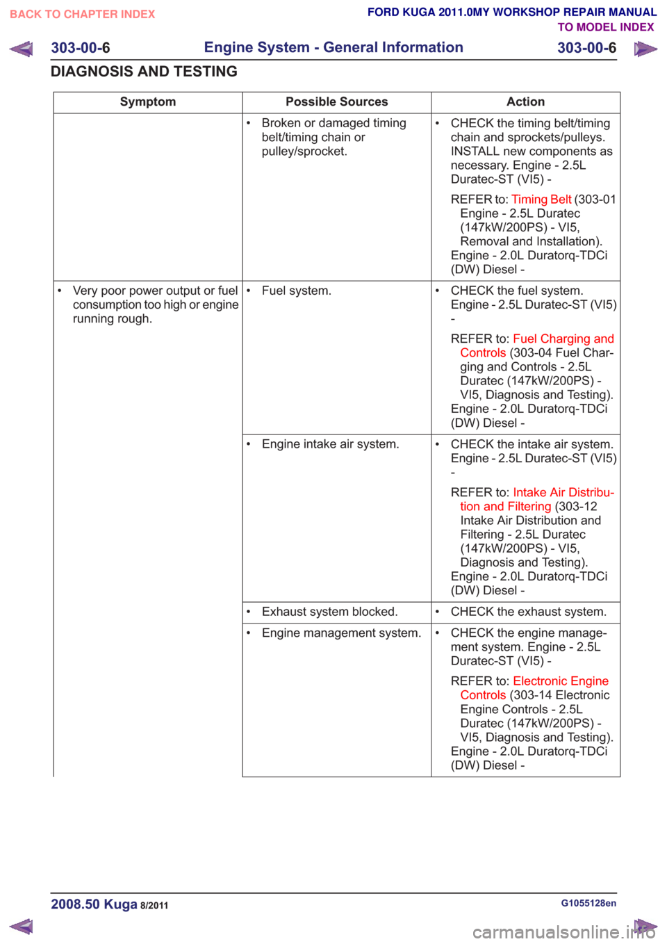
• CHECK the timing belt/timingchain and sprockets/pulleys.
INSTALL new components as
necessary. Engine - 2.5L
Duratec-ST (VI5) -
REFER to: Timing Belt (303-01
Engine - 2.5L Duratec
(147kW/200PS) - VI5,
Removal and Installation).
Engine - 2.0L Duratorq-TDCi
(DW) Diesel -
• Broken or damaged timing
belt/timing chain or
pulley/sprocket.
• CHECK the fuel system.Engine - 2.5L Duratec-ST (VI5)
-
REFER to: Fuel Charging and
Controls (303-04 Fuel Char-
ging and Controls - 2.5L
Duratec (147kW/200PS) -
VI5, Diagnosis and Testing).
Engine - 2.0L Duratorq-TDCi
(DW) Diesel -
• Fuel system.
• Very poor power output or fuel
consumption too high or engine
running rough.
• CHECK the intake air system.Engine - 2.5L Duratec-ST (VI5)
-
REFER to: Intake Air Distribu-
tion and Filtering (303-12
Intake Air Distribution and
Filtering - 2.5L Duratec
(147kW/200PS) - VI5,
Diagnosis and Testing).
Engine - 2.0L Duratorq-TDCi
(DW) Diesel -
• Engine intake air system.
• CHECK the exhaust system.
• Exhaust system blocked.
• CHECK the engine manage-ment system. Engine - 2.5L
Duratec-ST (VI5) -
REFER to: Electronic Engine
Controls (303-14 Electronic
Engine Controls - 2.5L
Duratec (147kW/200PS) -
VI5, Diagnosis and Testing).
Engine - 2.0L Duratorq-TDCi
(DW) Diesel -
• Engine management system.
G1055128en2008.50 Kuga8/2011
303-00-
6
Engine System - General Information
303-00- 6
DIAGNOSIS AND TESTING
TO MODEL INDEX
BACK TO CHAPTER INDEX
FORD KUGA 2011.0MY WORKSHOP REPAIR MANUAL
Page 1528 of 2057

TIE44583
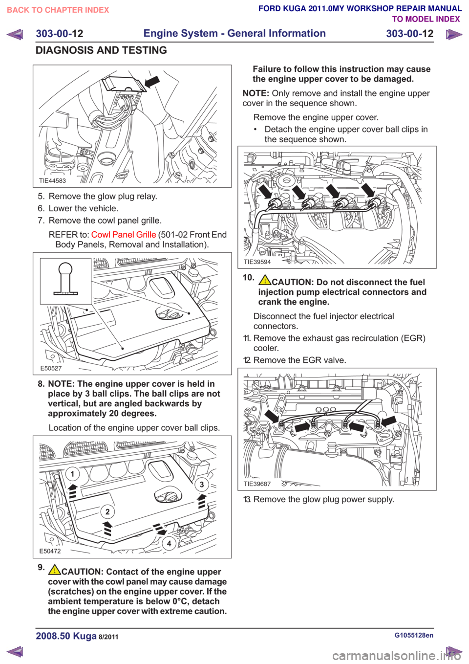
5. Remove the glow plug relay.
6. Lower the vehicle.
7. Remove the cowl panel grille.REFER to: Cowl Panel Grille (501-02 Front End
Body Panels, Removal and Installation).
E50527
8. NOTE: The engine upper cover is held in place by 3 ball clips. The ball clips are not
vertical, but are angled backwards by
approximately 20 degrees.
Location of the engine upper cover ball clips.
E50472
2
1
3
4
9.CAUTION: Contact of the engine upper
cover with the cowl panel may cause damage
(scratches) on the engine upper cover. If the
ambient temperature is below 0°C, detach
the engine upper cover with extreme caution. Failure to follow this instruction may cause
the engine upper cover to be damaged.
NOTE: Only remove and install the engine upper
cover in the sequence shown.
Remove the engine upper cover.• Detach the engine upper cover ball clips in the sequence shown.
TIE39594
10.CAUTION: Do not disconnect the fuel
injection pump electrical connectors and
crank the engine.
Disconnect the fuel injector electrical
connectors.
11. Remove the exhaust gas recirculation (EGR) cooler.
12. Remove the EGR valve.
TIE39687
13. Remove the glow plug power supply.
G1055128en2008.50 Kuga8/2011
303-00- 12
Engine System - General Information
303-00- 12
DIAGNOSIS AND TESTING
TO MODEL INDEX
BACK TO CHAPTER INDEX
FORD KUGA 2011.0MY WORKSHOP REPAIR MANUAL
Page 1534 of 2057

SECTION 303-01 Engine— 2.5L Duratec (147kW/200PS) - VI5
VEHICLE APPLICATION:2008.50 Kuga
PA G E
CONTENTS
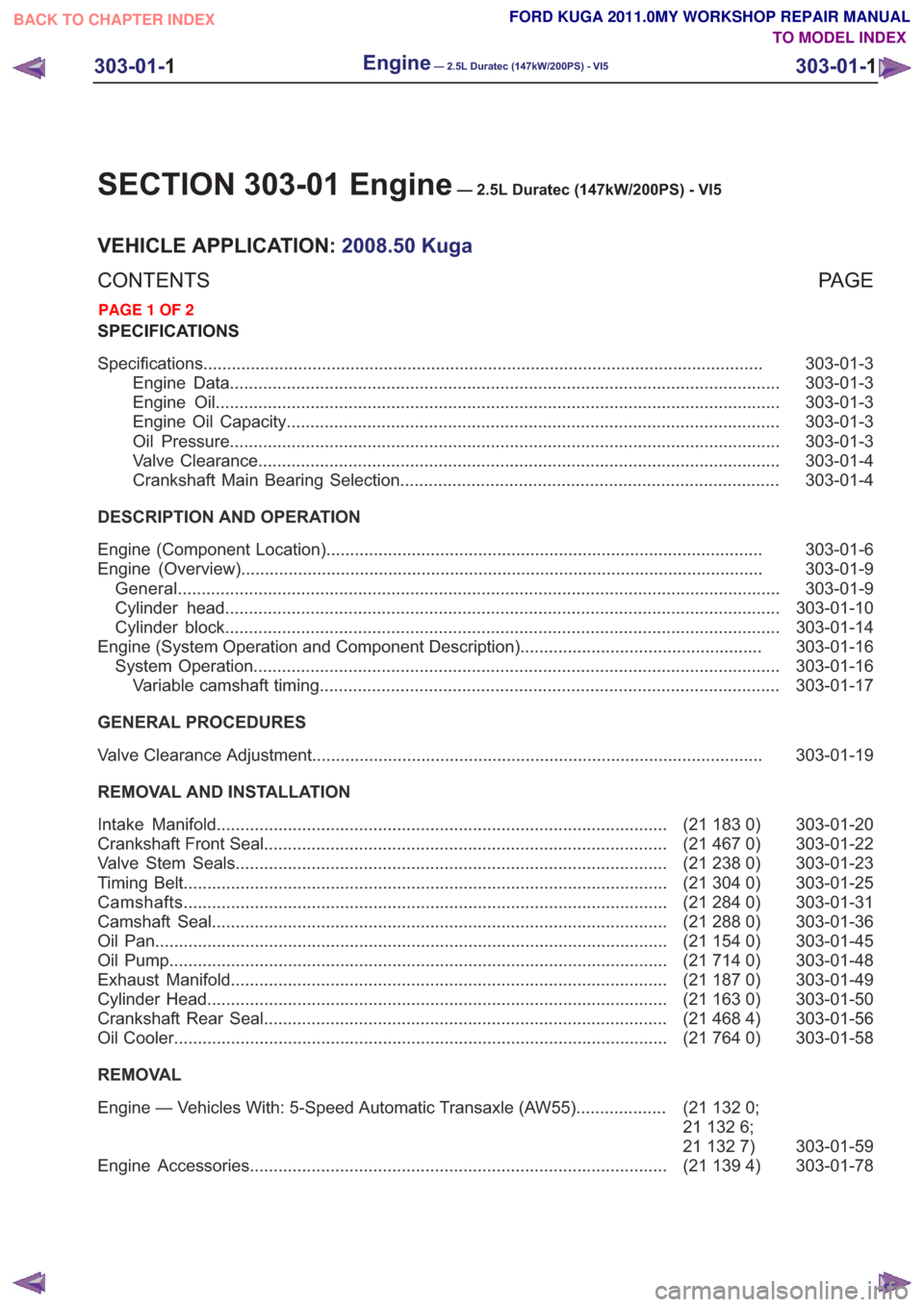
SPECIFICATIONS
303-01-3
Specifications ........................................................................\
..............................................
303-01-3
Engine Data ........................................................................\
............................................
303-01-3
Engine Oil ........................................................................\
...............................................
303-01-3
Engine Oil Capacity ........................................................................\
................................
303-01-3
Oil Pressure ........................................................................\
............................................
303-01-4
Valve Clearance ........................................................................\
......................................
303-01-4
Crankshaft Main Bearing Selection ........................................................................\
........
DESCRIPTION AND OPERATION 303-01-6
Engine (Component Location) ........................................................................\
....................
303-01-9
Engine (Overview) ........................................................................\
......................................
303-01-9
General ........................................................................\
.......................................................
303-01-10
Cylinder head ........................................................................\
.............................................
303-01-14
Cylinder block ........................................................................\
.............................................
303-01-16
Engine (System Operation and Component Description) ...................................................
303-01-16
System Operation ........................................................................\
.......................................
303-01-17
Variable camshaft timing ........................................................................\
.........................
GENERAL PROCEDURES 303-01-19
Valve Clearance Adjustment ........................................................................\
.......................
REMOVAL AND INSTALLATION 303-01-20
(21 183 0)
Intake Manifold ........................................................................\
.......................
303-01-22
(21 467 0)
Crankshaft Front Seal ........................................................................\
.............
303-01-23
(21 238 0)
Valve Stem Seals ........................................................................\
...................
303-01-25
(21 304 0)
Timing Belt ........................................................................\
..............................
303-01-31
(21 284 0)
Camshafts ........................................................................\
..............................
303-01-36
(21 288 0)
Camshaft Seal ........................................................................\
........................
303-01-45
(21 154 0)
Oil Pan ........................................................................\
....................................
303-01-48
(21 714 0)
Oil Pump ........................................................................\
.................................
303-01-49
(21 187 0)
Exhaust Manifold ........................................................................\
....................
303-01-50
(21 163 0)
Cylinder Head ........................................................................\
.........................
303-01-56
(21 468 4)
Crankshaft Rear Seal ........................................................................\
.............
303-01-58
(21 764 0)
Oil Cooler ........................................................................\
................................
REMOVAL
303-01-59
(21
132 0;
21 132 6;
21 132 7)
Engine — Vehicles With: 5-Speed Automatic Transaxle (AW55)
...................
303-01-78
(21 139 4)
Engine Accessories ........................................................................\
................
303-01-1
Engine— 2.5L Duratec (147kW/200PS) - VI5303-01-
1
.
TO MODEL INDEX
BACK TO CHAPTER INDEX
PAGE 1 OF 2 FORD KUGA 2011.0MY WORKSHOP REPAIR MANUAL
Page 1537 of 2057

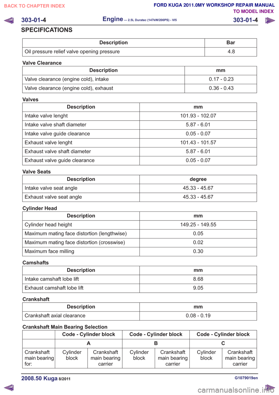
Bar
Description
4.8
Oil pressure relief valve opening pressure
Valve Clearance
mm
Description
0.17 - 0.23
Valve clearance (engine cold), intake
0.36 - 0.43
Valve clearance (engine cold), exhaust
Valves
mm
Description
101.93 - 102.07
Intake valve lenght
5.87 - 6.01
Intake valve shaft diameter
0.05 - 0.07
Intake valve guide clearance
101.43 - 101.57
Exhaust valve lenght
5.87 - 6.01
Exhaust valve shaft diameter
0.05 - 0.07
Exhaust valve guide clearance
Valve Seats
degree
Description
45.33 - 45.67
Intake valve seat angle
45.33 - 45.67
Exhaust valve seat angle
Cylinder Head
mm
Description
149.25 - 149.55
Cylinder head height
0.05
Maximum mating face distortion (lengthwise)
0.02
Maximum mating face distortion (crosswise)
0.30
Maximum face milling
Camshafts
mm
Description
8.68
Intake camshaft lobe lift
9.05
Exhaust camshaft lobe lift
Crankshaft
mm
Description
0.08 - 0.19
Crankshaft axial clearance
Crankshaft Main Bearing Selection
Code - Cylinder block
Code - Cylinder block
Code - Cylinder block
C
B
A
Crankshaft
main bearing carrier
Cylinder
block
Crankshaft
main bearing carrier
Cylinder
block
Crankshaft
main bearing carrier
Cylinder
block
Crankshaft
main bearing
for:
G1079019en2008.50 Kuga8/2011
303-01-
4
Engine— 2.5L Duratec (147kW/200PS) - VI5303-01-
4
SPECIFICATIONS
TO MODEL INDEX
BACK TO CHAPTER INDEX
FORD KUGA 2011.0MY WORKSHOP REPAIR MANUAL
Page 1539 of 2057
Engine – Component Location
Engine
E62441
1
65
4
3
2
9
10
13
12
11
8
7
Description
Item
Front engine cover
1
Rear engine cover
2
CMP (camshaft position) Sensor - intake
camshaft
3
CMP Sensor - exhaust camshaft
4Description
Item
Intake variable camshaft timing oil control
solenoid
5
Exhaust variable camshaft timing oil
control solenoid
6
Exhaust VCT control unit
7
Intake VCT control unit
8
G1032415en2008.50 Kuga8/2011
303-01- 6
Engine— 2.5L Duratec (147kW/200PS) - VI5303-01-
6
DESCRIPTION AND OPERATION
TO MODEL INDEX
BACK TO CHAPTER INDEX
FORD KUGA 2011.0MY WORKSHOP REPAIR MANUAL
Page 1543 of 2057
2
E62614
1
Description
Item
Engine speed curve
1
Power output curve
2
By the use of VCT for the intake and exhaust
camshafts it is possible to attain maximum torque
across a wide engine speed range.
Cylinder head
The cylinder head consists of two parts. The top
half of the cylinder head consists of a valve cover
with integral camshaft bearing caps.
G1092773en2008.50 Kuga8/2011
303-01- 10
Engine— 2.5L Duratec (147kW/200PS) - VI5303-01-
10
DESCRIPTION AND OPERATION
TO MODEL INDEX
BACK TO CHAPTER INDEX
FORD KUGA 2011.0MY WORKSHOP REPAIR MANUAL
Page 1544 of 2057
E62857
1
2
3
6
5
4
Description
Item
Camshaft bearings
1
Valve cover
2
Cylinder head
3Description
Item
Spark plug well sealing ring
4
Exhaust camshaft
5
intake camshaft
6
A conventional cylinder head gasket is installed
between the cylinder head and the cylinder block. The gaskets between the other mating faces are
fluid gaskets.
G1092773en2008.50 Kuga8/2011
303-01-
11
Engine— 2.5L Duratec (147kW/200PS) - VI5303-01-
11
DESCRIPTION AND OPERATION
TO MODEL INDEX
BACK TO CHAPTER INDEX
FORD KUGA 2011.0MY WORKSHOP REPAIR MANUAL