2011 FORD KUGA Pinpoint Test g
[x] Cancel search: Pinpoint Test gPage 229 of 2057

Action
Possible Source
Description
DTC
CHECK parking aid sensor
for contamination. IF a
parking sensor is OK.
INSTALL a new parking aid
sensor. TEST the system for
normal operation.
•
Rear outer left parking aid
sensor.
Concern with rear outer left
parking aid sensor
C1701
CHECK the circuit 8-GN19
(WH) for short to battery. IF
the circuit is OK, INSTALL a
new parking aid module.
REFER to:Parking Aid
Module (413-13 Parking
Aid, Removal and Installa-
tion).
TEST the system for normal
operation.
• Parking aid sensor signal
circuit.
• Parking aid module.
Rear outer right sensor
signal circuit short to battery
C1702
GO toPinpoint Test D.
• Parking aid sensor signal
circuit.
• Parking aid sensor.
• Parking aid module.
Rear outer right sensor
signal circuit open or short
to ground
C1703
CHECK parking aid sensor
for contamination. IF a
parking sensor is OK.
INSTALL a new parking aid
sensor. TEST the system for
normal operation.
• Rear outer right parking
aid sensor.
Concern with rear outer right
parking aid sensor
C1704
CHECK the circuit 8-GN21
(WH/BU) for short to battery.
IF the circuit is OK, INSTALL
a new parking aid module.
REFER to:Parking Aid
Module (413-13 Parking
Aid, Removal and Installa-
tion).
TEST the system for normal
operation.
• Parking aid sensor signal
circuit.
• Parking aid module.
Rear inner left sensor signal
circuit short to battery
C1705
GO toPinpoint Test E.
• Parking aid sensor signal
circuit.
• Parking aid sensor.
• Parking aid module.
Rear inner left sensor signal
circuit open or short to
ground
C1706
CHECK parking aid sensor
for contamination. IF a
parking sensor is OK.
INSTALL a new parking aid
sensor. TEST the system for
normal operation.
•
Rear inner left parking aid
sensor.
Concern with rear inner left
parking aid sensor
C1707 G295937en
2008.50 Kuga 8/2011 413-13-30
Parking Aid
413-13-30
DIAGNOSIS AND TESTINGTO MODEL INDEX
BACK TO CHAPTER INDEX
FORD KUGA 2011.0MY WORKSHOP REPAIR MANUAL
Page 230 of 2057

Action
Possible Source
Description
DTC
CHECK the circuit 8-GN20
(WH/RD) for short to battery.
IF the circuit is OK, INSTALL
a new parking aid module.
REFER to:Parking Aid
Module (413-13 Parking
Aid, Removal and Installa-
tion).
TEST the system for normal
operation.
• Parking aid sensor signal
circuit.
• Parking aid module.
Rear inner right sensor
signal circuit short to battery
C1708
GO toPinpoint Test F.
• Parking aid sensor signal
circuit.
• Parking aid sensor.
• Parking aid module.
Rear inner right sensor
signal circuit open or short
to ground
C1709
CHECK parking aid sensor
for contamination. IF a
parking sensor is OK.
INSTALL a new parking aid
sensor. TEST the system for
normal operation.
• Rear inner right parking
aid sensor.
Concern with rear inner right
parking aid sensor
C1710
GO toPinpoint Test G.
• Parking aid sensors
voltage supply circuits.
Parking aid sensor voltage
supply short to ground
B1299
GO toPinpoint Test H.
• Parking aid module.
• circuit(s).
Parking aid speaker circuit
short to ground
C1742
GO toPinpoint Test I.
• Parking aid module.
• circuit(s).
Parking aid speaker circuit
short to battery
C1743
INSTALL a new parking aid
module.
REFER to:Parking Aid
Module (413-13 Parking
Aid, Removal and Installa-
tion).
TEST the system for normal
operation.
• Parking aid module.
RAM Error
B1342
INSTALL a new parking aid
module.
REFER to:Parking Aid
Module (413-13 Parking
Aid, Removal and Installa-
tion).
TEST the system for normal
operation.
• Parking aid module.
ROM/EEPROM Error
B2477 G295937en
2008.50 Kuga 8/2011 413-13-31
Parking Aid
413-13-31
DIAGNOSIS AND TESTINGTO MODEL INDEX
BACK TO CHAPTER INDEX
FORD KUGA 2011.0MY WORKSHOP REPAIR MANUAL
Page 287 of 2057

SECTION 415-00 Information and Entertainment
System - General Information
VEHICLE APPLICATION:
2008.50 Kuga
PAGE
CONTENTS
DIAGNOSIS AND TESTING
415-00-2
Audio System......................................................................................................................
415-00-2
Inspection and Verification..................................................................................................
415-00-2
Self-Diagnostic Mode - Low Series Audio Unit...................................................................
415-00-2
Self-Diagnostic Mode - High Series Audio Unit GEN 2......................................................
415-00-4
Cellular Phone....................................................................................................................
415-00-4
Principles of Operation.......................................................................................................
415-00-4
Inspection and Verification..................................................................................................
415-00-5
Diagnostic Trouble Code (DTC) Index Chart......................................................................
415-00-6
Symptom Chart...................................................................................................................
415-00-7
Pinpoint Tests..................................................................................................................... 415-00-1
Information and Entertainment System -
General Information
415-00-1
.TO MODEL INDEX
BACK TO CHAPTER INDEX
FORD KUGA 2011.0MY WORKSHOP REPAIR MANUAL
Page 290 of 2057

Cellular Phone
Refer to
Wiring Diagrams Section 415-00, for
schematic and connector information. General Equipment
Ford diagnostic equipment
Principles of Operation
NOTE: Voice control will only operate with the
audio unit and components required switched ON.
Voice Control
The portable support electronics (PSE) module
has a voice control system. The customer will be
able to push the VOICE button on the audio control
switch located on the steering column lower
shroud, this will activate the PSE module and allow
voice control. An audible tone will be heard through
the audio unit speakers after which, a voice
command can then be spoken into the microphone
located in the overhead console.
The incoming calls and voice confirmation can be
heard through the audio system speakers.
When a voice command is spoken into the
microphone it will be sent as a signal to the PSE
module. The signal is then sent from the PSE
module to the relevant components on the
medium-speed controller area network (CAN) bus
network. The component will then convert the
signal back into the original voice command.
The components that the PSE module interacts
with are as follows:
• audio unit
• navigation system display module
• cellular phone
For additional information on the cellular phone
system, REFER to the cellular phone Owner's
Guide.
Bluetooth
An input can be given through the cellular phone
with or without the cellular phone connected to the
handset holder. Providing that the cellular phone
is one of the recommended cellular phones for the
system, is supplied with the Bluetooth technology
and the cellular phone is programmed to the PSE
module.
When selected as active the Bluetooth technology
is a wireless system that interacts with the relevant component modules through the PSE module. The
general operation of the Bluetooth is similar to the
voice control.
Bluetooth technology cannot transfer the cellular
phone's PHONEBOOK or recent outgoing and
incoming call details to the audio unit or navigation
system display module. If the cellular phone is
placed into the handset holder the PHONEBOOK
data and recent outgoing and incoming call
information will be transferred to the audio unit or
navigation system display module.
For additional information, REFER to the cellular
phone Owner's Guide.
Inspection and Verification
NOTE: Make sure that the cellular phone is
featured on the list of recommended cellular
phones for the system.
Make sure that the PSE module and cellular
phone are configured to each other before
starting a system diagnosis. ENTER the
following PIN number on the cellular phone to
configure the cellular phone to the PSE module:
0000.
Make sure that the MUTE symbol is not
displayed on the audio unit when trying to
operate the cellular phone system. If the MUTE
symbol is displayed, this indicates that the PSE
module requires configuring to the vehicle and
the cellular phone requires programming to the
PSE module. GO to
Pinpoint Test C.
1. Verify the customer concern by operating the system using the customers cellular phone.
2. Visually inspect for obvious signs of electrical damage.
Visual Inspection Chart Electrical
• Fuse(s)
• Wiring harness
• Electrical connector(s)
• Cellular phone
• Microphone
• PSE module
• Audio unit
• Instrument cluster
• Navigation system display module G1189085en
2008.50 Kuga 8/2011 415-00-4
Information and Entertainment System -
General Information
415-00-4
DIAGNOSIS AND TESTINGTO MODEL INDEX
BACK TO CHAPTER INDEX
FORD KUGA 2011.0MY WORKSHOP REPAIR MANUAL
Page 291 of 2057

3. If an obvious cause for an observed or reported
concern is found, correct the cause (if possible)
before proceeding to the next step.
4. If the cause is not visually evident, connect the Ford diagnostic equipment to the data link
connector (DLC).
5. SELECT the TOOLBOXmenu.
6. SELECT the ENTERTAINMENT/COMMUNICATION menu.7. SELECT the
SPEECH RECOGNITION
MODULE option and follow the instructions on
the display.
8. Retrieve the diagnostic trouble codes (DTC)s and refer to the Diagnostic Trouble Code (DTC)
Index Chart.
9. If no DTCs are retrieved or there is no communication with the module, proceed to the
Symptom Chart to continue diagnostics.
Diagnostic Trouble Code (DTC) Index Chart Action
Possible Source
Description/Condition
DTC
GO toPinpoint Test B.
Microphone defect or
short to ground
Microphone input circuit
failure
B1038
REFER to:Charging
System (414-00 Char-
ging System - General
Information, Diagnosis and Testing).
Battery voltage above
16 volts
Battery voltage high
B1317
REFER to:Charging
System (414-00 Char-
ging System - General
Information, Diagnosis and Testing).
Battery voltage below 9
volts
Battery voltage low
B1318
INSTALL a new PSEmodule. TEST the
system for normal oper- ation.
PSE module
PSE module failure
B1342
GO toPinpoint Test B.
Microphone defect or
not connected
Microphone input signal
circuit open
B1899
GO toPinpoint Test B.
No supply to micro-
phone
Microphone bias circuit
failure
B2272
REFER to the Ford
diagnostic equipment.
PSE module
Faulty module configura-
tion
B2477 G1189085en
2008.50 Kuga 8/2011 415-00-5
Information and Entertainment System -
General Information
415-00-5
DIAGNOSIS AND TESTINGTO MODEL INDEX
BACK TO CHAPTER INDEX
FORD KUGA 2011.0MY WORKSHOP REPAIR MANUAL
Page 292 of 2057

Action
Possible Source
Description/Condition
DTC
CHECK the cellular
phone Bluetooth func-
tion with another applic- ation to determine if the cellular phone is the
concern. If the Bluetooth function operates
correctly with the other
application, INSTALL a
new PSE module. TEST the system for normal operation. If the
Bluetooth function does not operate with other
application, REFER to the cellular phoneOwner's Guide.
PSE module or cellular
phone
Bluetooth communica-
tion failure to cellular phone
U0074
INSTALL a new PSEmodule. TEST the
system for normal oper- ation.
PSE module
No application present
U2050
1. If the cause is not visually evident, verify the symptom and refer to the Symptom Chart.
Symptom Chart Action
Possible Sources
Symptom
• GO toPinpoint Test C.
• PSE module not configured to
the vehicle.
• No communication with the
portable support electronics
(PSE) module
• GO toPinpoint Test A.
• Fuse(s).
• Circuit(s).
• PSE module.
• REFER to:Communications
Network (418-00 Module
Communications Network,
Diagnosis and Testing).
• DLC.
• GO toPinpoint Test C.
• PSE module not configured to
the vehicle.
•
The audio unit display does not
display PHONE
• CHECK all communicationbetween the instrument cluster,
audio unit, navigation system
display module and PSE
module. REFER to the Ford
diagnostic equipment.
• Audio unit.
• Navigation system display
module.
• PSE module.
• Instrument cluster.
• GO toPinpoint Test B.
• Circuit(s).
• Microphone.
• PSE module.
•
The cellular phone microphone
is not operating correctly G1189085en
2008.50 Kuga 8/2011 415-00-6
Information and Entertainment System -
General Information
415-00-6
DIAGNOSIS AND TESTINGTO MODEL INDEX
BACK TO CHAPTER INDEX
FORD KUGA 2011.0MY WORKSHOP REPAIR MANUAL
Page 293 of 2057

Action
Possible Sources
Symptom
• CHECK all communicationbetween the audio unit and
PSE module. REFER to the
Ford diagnostic equipment.
• Audio unit.
• PSE module.
• Reduced sound or no sound
through the speakers
• REFER to the Ford diagnosticequipment.
• Circuit(s).
• Audio unit.
• PSE module.
• CHECK all communicationbetween the instrument cluster,
audio unit, navigation system
display module and PSE
module. REFER to the Ford
diagnostic equipment.
• Audio unit.
• Navigation system display
module.
• PSE module.
• Instrument cluster.
• The cellular phone information
is not displayed
• CHECK all communicationbetween the instrument cluster,
audio unit, navigation system
display module and PSE
module. REFER to the Ford
diagnostic equipment.
• Circuit(s).
• Cellular Phone.
• Audio unit.
• Navigation system display
module.
• PSE module.
• Instrument cluster.
• The voice activated phone
functions are inoperative
• CHECK the make and modelof the cellular phone against
those on the list of recom-
mended cellular phones for the
system.
• Cellular phone is not featured
on the list of recommended
cellular phones for the system
Pinpoint Tests
NOTE: ENTER the following PIN number on the
cellular phone to configure the cellular phone to
the PSE module: 0000. NOTE:
Use a digital multimeter for all electrical
measurements.
PINPOINT TEST A : NO COMMUNICATION WITH THE PORTABLE SUPPORT ELECTRONICS (PSE)
MODULE DETAILS/RESULTS/ACTIONS
TEST CONDITIONS
A1: CHECK FOR VOLTAGE AT THE PSE MODULE 1
Disconnect PSE Module C432. G1189085en
2008.50 Kuga 8/2011 415-00-7
Information and Entertainment System -
General Information
415-00-7
DIAGNOSIS AND TESTINGTO MODEL INDEX
BACK TO CHAPTER INDEX
FORD KUGA 2011.0MY WORKSHOP REPAIR MANUAL
Page 1158 of 2057
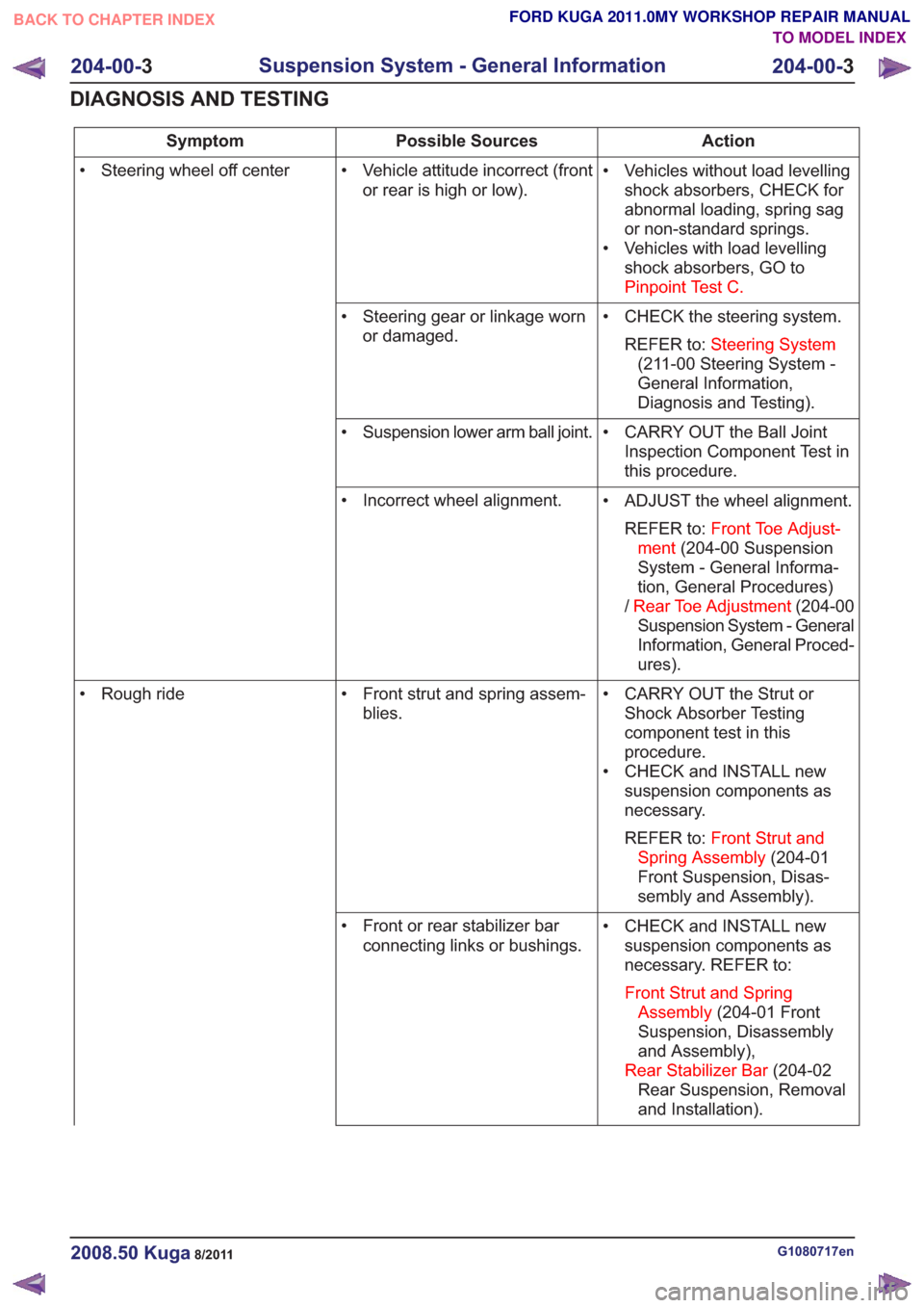
Action
Possible Sources
Symptom
• Vehicles without load levellingshock absorbers, CHECK for
abnormal loading, spring sag
or non-standard springs.
• Vehicles with load levelling shock absorbers, GO to
Pinpoint Test C.
• Vehicle attitude incorrect (front
or rear is high or low).
• Steering wheel off center
• CHECK the steering system.REFER to: Steering System
(211-00 Steering System -
General Information,
Diagnosis and Testing).
• Steering gear or linkage worn
or damaged.
• CARRY OUT the Ball JointInspection Component Test in
this procedure.
• Suspension lower arm ball joint.
• ADJUST the wheel alignment.REFER to: Front Toe Adjust-
ment (204-00 Suspension
System - General Informa-
tion, General Procedures)
/ Rear Toe Adjustment (204-00
Suspension System - General
Information, General Proced-
ures).
• Incorrect wheel alignment.
• CARRY OUT the Strut orShock Absorber Testing
component test in this
procedure.
• CHECK and INSTALL new suspension components as
necessary.
REFER to: Front Strut and
Spring Assembly (204-01
Front Suspension, Disas-
sembly and Assembly).
• Front strut and spring assem-
blies.
• Rough ride
• CHECK and INSTALL newsuspension components as
necessary. REFER to:
Front Strut and Spring Assembly (204-01 Front
Suspension, Disassembly
and Assembly),
Rear Stabilizer Bar (204-02
Rear Suspension, Removal
and Installation).
• Front or rear stabilizer bar
connecting links or bushings.
G1080717en2008.50 Kuga8/2011
204-00- 3
Suspension System - General Information
204-00- 3
DIAGNOSIS AND TESTING
TO MODEL INDEX
BACK TO CHAPTER INDEX
FORD KUGA 2011.0MY WORKSHOP REPAIR MANUAL