2011 FORD KUGA Fuel tank
[x] Cancel search: Fuel tankPage 1703 of 2057
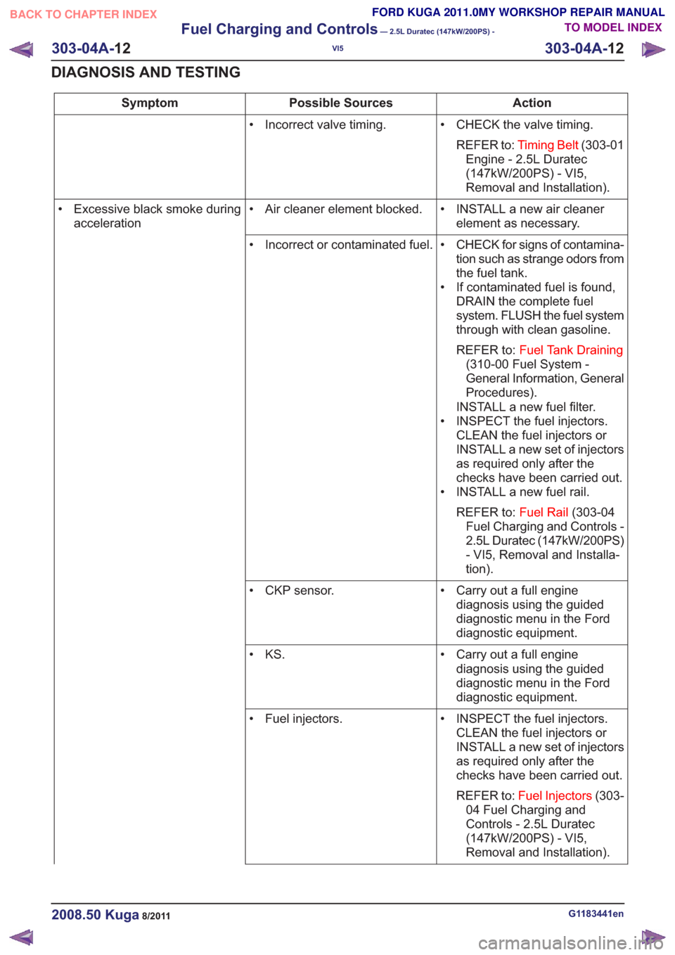
Action
Possible Sources
Symptom
• CHECK the valve timing.REFER to: Timing Belt (303-01
Engine - 2.5L Duratec
(147kW/200PS) - VI5,
Removal and Installation).
• Incorrect valve timing.
• INSTALL a new air cleanerelement as necessary.
• Air cleaner element blocked.
• Excessive black smoke during
acceleration
• CHECK for signs of contamina-tion such as strange odors from
the fuel tank.
• If contaminated fuel is found, DRAIN the complete fuel
system. FLUSH the fuel system
through with clean gasoline.
REFER to: Fuel Tank Draining
(310-00 Fuel System -
General Information, General
Procedures).
INSTALL a new fuel filter.
• INSPECT the fuel injectors. CLEAN the fuel injectors or
INSTALL a new set of injectors
as required only after the
checks have been carried out.
• INSTALL a new fuel rail.
REFER to: Fuel Rail(303-04
Fuel Charging and Controls -
2.5L Duratec (147kW/200PS)
- VI5, Removal and Installa-
tion).
• Incorrect or contaminated fuel.
• Carry out a full enginediagnosis using the guided
diagnostic menu in the Ford
diagnostic equipment.
• CKP sensor.
• Carry out a full enginediagnosis using the guided
diagnostic menu in the Ford
diagnostic equipment.
• KS.
• INSPECT the fuel injectors.CLEAN the fuel injectors or
INSTALL a new set of injectors
as required only after the
checks have been carried out.
REFER to: Fuel Injectors (303-
04 Fuel Charging and
Controls - 2.5L Duratec
(147kW/200PS) - VI5,
Removal and Installation).
• Fuel injectors.
G1183441en2008.50 Kuga8/2011
303-04A-
12
Fuel Charging and Controls
— 2.5L Duratec (147kW/200PS) -
VI5
303-04A- 12
DIAGNOSIS AND TESTING
TO MODEL INDEX
BACK TO CHAPTER INDEX
FORD KUGA 2011.0MY WORKSHOP REPAIR MANUAL
Page 1705 of 2057
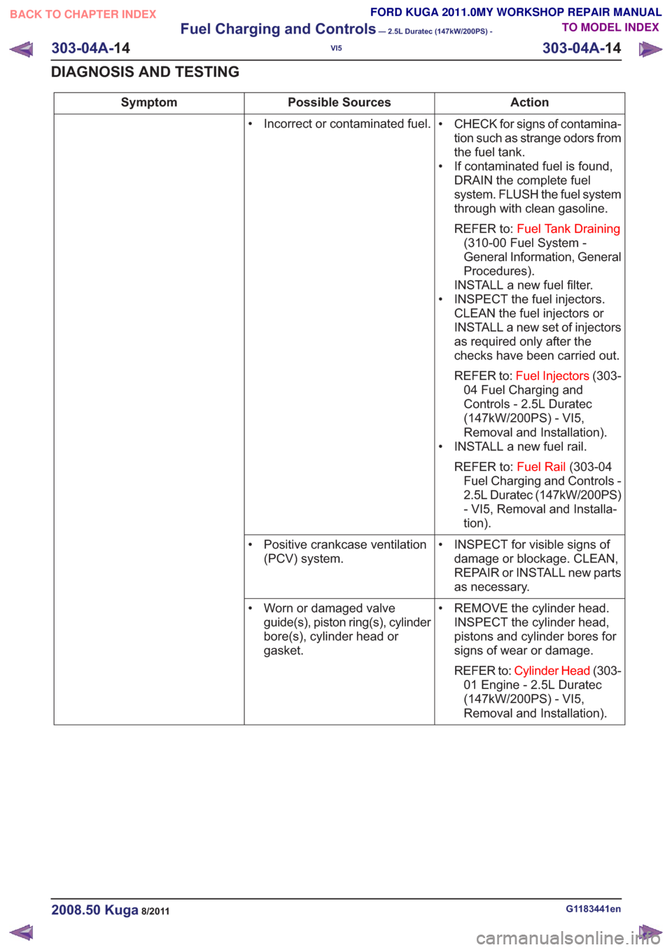
Action
Possible Sources
Symptom
• CHECK for signs of contamina-tion such as strange odors from
the fuel tank.
• If contaminated fuel is found, DRAIN the complete fuel
system. FLUSH the fuel system
through with clean gasoline.
REFER to: Fuel Tank Draining
(310-00 Fuel System -
General Information, General
Procedures).
INSTALL a new fuel filter.
• INSPECT the fuel injectors. CLEAN the fuel injectors or
INSTALL a new set of injectors
as required only after the
checks have been carried out.
REFER to: Fuel Injectors (303-
04 Fuel Charging and
Controls - 2.5L Duratec
(147kW/200PS) - VI5,
Removal and Installation).
• INSTALL a new fuel rail.
REFER to: Fuel Rail(303-04
Fuel Charging and Controls -
2.5L Duratec (147kW/200PS)
- VI5, Removal and Installa-
tion).
• Incorrect or contaminated fuel.
• INSPECT for visible signs ofdamage or blockage. CLEAN,
REPAIR or INSTALL new parts
as necessary.
• Positive crankcase ventilation
(PCV) system.
• REMOVE the cylinder head.INSPECT the cylinder head,
pistons and cylinder bores for
signs of wear or damage.
REFER to: Cylinder Head (303-
01 Engine - 2.5L Duratec
(147kW/200PS) - VI5,
Removal and Installation).
• Worn or damaged valve
guide(s), piston ring(s), cylinder
bore(s), cylinder head or
gasket.
G1183441en2008.50 Kuga8/2011
303-04A- 14
Fuel Charging and Controls
— 2.5L Duratec (147kW/200PS) -
VI5
303-04A- 14
DIAGNOSIS AND TESTING
TO MODEL INDEX
BACK TO CHAPTER INDEX
FORD KUGA 2011.0MY WORKSHOP REPAIR MANUAL
Page 1706 of 2057
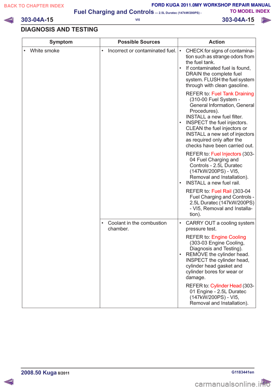
Action
Possible Sources
Symptom
• CHECK for signs of contamina-tion such as strange odors from
the fuel tank.
• If contaminated fuel is found, DRAIN the complete fuel
system. FLUSH the fuel system
through with clean gasoline.
REFER to: Fuel Tank Draining
(310-00 Fuel System -
General Information, General
Procedures).
INSTALL a new fuel filter.
• INSPECT the fuel injectors. CLEAN the fuel injectors or
INSTALL a new set of injectors
as required only after the
checks have been carried out.
REFER to: Fuel Injectors (303-
04 Fuel Charging and
Controls - 2.5L Duratec
(147kW/200PS) - VI5,
Removal and Installation).
• INSTALL a new fuel rail.
REFER to: Fuel Rail(303-04
Fuel Charging and Controls -
2.5L Duratec (147kW/200PS)
- VI5, Removal and Installa-
tion).
• Incorrect or contaminated fuel.
• White smoke
• CARRY OUT a cooling systempressure test.
REFER to: Engine Cooling
(303-03 Engine Cooling,
Diagnosis and Testing).
• REMOVE the cylinder head. INSPECT the cylinder head,
cylinder head gasket and
cylinder bores for wear or
damage.
REFER to: Cylinder Head (303-
01 Engine - 2.5L Duratec
(147kW/200PS) - VI5,
Removal and Installation).
• Coolant in the combustion
chamber.
G1183441en2008.50 Kuga8/2011
303-04A- 15
Fuel Charging and Controls
— 2.5L Duratec (147kW/200PS) -
VI5
303-04A- 15
DIAGNOSIS AND TESTING
TO MODEL INDEX
BACK TO CHAPTER INDEX
FORD KUGA 2011.0MY WORKSHOP REPAIR MANUAL
Page 1707 of 2057
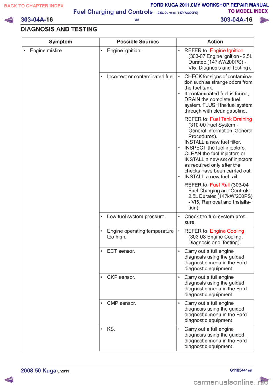
Action
Possible Sources
Symptom
• REFER to:Engine Ignition
(303-07 Engine Ignition - 2.5L
Duratec (147kW/200PS) -
VI5, Diagnosis and Testing).
• Engine ignition.
• Engine misfire
• CHECK for signs of contamina-tion such as strange odors from
the fuel tank.
• If contaminated fuel is found, DRAIN the complete fuel
system. FLUSH the fuel system
through with clean gasoline.
REFER to: Fuel Tank Draining
(310-00 Fuel System -
General Information, General
Procedures).
INSTALL a new fuel filter.
• INSPECT the fuel injectors. CLEAN the fuel injectors or
INSTALL a new set of injectors
as required only after the
checks have been carried out.
• INSTALL a new fuel rail.
REFER to: Fuel Rail(303-04
Fuel Charging and Controls -
2.5L Duratec (147kW/200PS)
- VI5, Removal and Installa-
tion).
• Incorrect or contaminated fuel.
• Check the fuel system pres-sure.
• Low fuel system pressure.
• REFER to:Engine Cooling
(303-03 Engine Cooling,
Diagnosis and Testing).
• Engine operating temperature
too high.
• Carry out a full enginediagnosis using the guided
diagnostic menu in the Ford
diagnostic equipment.
• ECT sensor.
• Carry out a full enginediagnosis using the guided
diagnostic menu in the Ford
diagnostic equipment.
• CKP sensor.
• Carry out a full enginediagnosis using the guided
diagnostic menu in the Ford
diagnostic equipment.
• CMP sensor.
• Carry out a full enginediagnosis using the guided
diagnostic menu in the Ford
diagnostic equipment.
• KS.
G1183441en2008.50 Kuga8/2011
303-04A-
16
Fuel Charging and Controls
— 2.5L Duratec (147kW/200PS) -
VI5
303-04A- 16
DIAGNOSIS AND TESTING
TO MODEL INDEX
BACK TO CHAPTER INDEX
FORD KUGA 2011.0MY WORKSHOP REPAIR MANUAL
Page 1709 of 2057
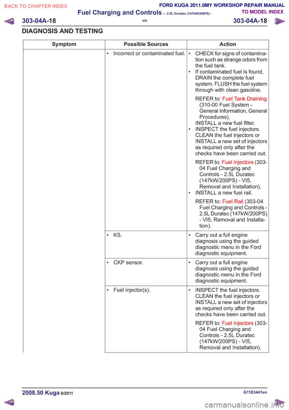
Action
Possible Sources
Symptom
• CHECK for signs of contamina-tion such as strange odors from
the fuel tank.
• If contaminated fuel is found, DRAIN the complete fuel
system. FLUSH the fuel system
through with clean gasoline.
REFER to: Fuel Tank Draining
(310-00 Fuel System -
General Information, General
Procedures).
INSTALL a new fuel filter.
• INSPECT the fuel injectors. CLEAN the fuel injectors or
INSTALL a new set of injectors
as required only after the
checks have been carried out.
REFER to: Fuel Injectors (303-
04 Fuel Charging and
Controls - 2.5L Duratec
(147kW/200PS) - VI5,
Removal and Installation).
• INSTALL a new fuel rail.
REFER to: Fuel Rail(303-04
Fuel Charging and Controls -
2.5L Duratec (147kW/200PS)
- VI5, Removal and Installa-
tion).
• Incorrect or contaminated fuel.
• Carry out a full enginediagnosis using the guided
diagnostic menu in the Ford
diagnostic equipment.
• KS.
• Carry out a full enginediagnosis using the guided
diagnostic menu in the Ford
diagnostic equipment.
• CKP sensor.
• INSPECT the fuel injectors.CLEAN the fuel injectors or
INSTALL a new set of injectors
as required only after the
checks have been carried out.
REFER to: Fuel Injectors (303-
04 Fuel Charging and
Controls - 2.5L Duratec
(147kW/200PS) - VI5,
Removal and Installation).
• Fuel injector(s).
G1183441en2008.50 Kuga8/2011
303-04A-
18
Fuel Charging and Controls
— 2.5L Duratec (147kW/200PS) -
VI5
303-04A- 18
DIAGNOSIS AND TESTING
TO MODEL INDEX
BACK TO CHAPTER INDEX
FORD KUGA 2011.0MY WORKSHOP REPAIR MANUAL
Page 1790 of 2057
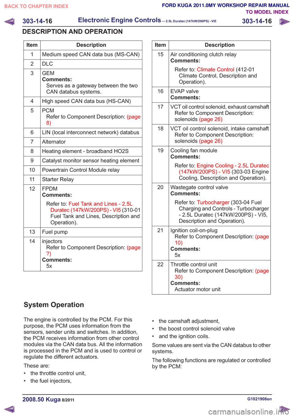
Description
Item
Medium speed CAN data bus (MS-CAN)
1
DLC
2
GEM
Comments:Serves as a gateway between the two
CAN databus systems.
3
High speed CAN data bus (HS-CAN)
4
PCMRefertoComponentDescription:(page
8)
5
LIN (local interconnect network) databus
6
Alternator
7
Heating element - broadband HO2S
8
Catalyst monitor sensor heating element
9
Powertrain Control Module relay
10
Starter Relay
11
FPDM
Comments:Refer to: Fuel Tank and Lines - 2.5L
Duratec (147kW/200PS) - VI5 (310-01
Fuel Tank and Lines, Description and
Operation).
12
Fuel pump
13
injectorsRefertoComponentDescription:(page
?)
Comments: 5x
14Description
Item
Air conditioning clutch relay
Comments:Refer to: Climate Control (412-01
Climate Control, Description and
Operation).
15
EVAP valve
Comments:
16
VCT oil control solenoid, exhaust camshaftRefer to Component Description:
solenoids(page26)
17
VCT oil control solenoid, intake camshaftRefer to Component Description:
solenoids(page26)
18
Cooling fan module
Comments:Refer to: Engine Cooling - 2.5L Duratec
(147kW/200PS) - VI5 (303-03 Engine
Cooling, Description and Operation).
19
Wastegate control valve
Comments:Refer to: Turbocharger (303-04 Fuel
Charging and Controls - Turbocharger
- 2.5L Duratec (147kW/200PS) - VI5,
Description and Operation).
20
Ignition coil-on-plugRefertoComponentDescription:(page
10)
Comments: 5x
21
Throttle control unitRefertoComponentDescription:(page
30)
Comments: Actuator motor unit
22
System Operation
The engine is controlled by the PCM. For this
purpose, the PCM uses information from the
sensors, sender units and switches. In addition,
the PCM receives information from other control
modules via the CAN data bus. All the information
is processed in the PCM and is used to control or
regulate the different actuators.
These are:
• the throttle control unit,
• the fuel injectors, • the camshaft adjustment,
• the boost control solenoid valve
• and the ignition coils.
Some values are sent via the CAN databus to other
systems.
The following functions are regulated or controlled
by the PCM:
G1021908en2008.50 Kuga8/2011
303-14-
16
Electronic Engine Controls— 2.5L Duratec (147kW/200PS) - VI5303-14-
16
DESCRIPTION AND OPERATION
TO MODEL INDEX
BACK TO CHAPTER INDEX
FORD KUGA 2011.0MY WORKSHOP REPAIR MANUAL
Page 1792 of 2057
• Torque reduction request (stability assistmodule)
• Cruise control request
The PCM sends the following signals via the CAN
databus:
• Fuel pump relay on/off
• Engine speed
• Warning lights on/off (MIL (malfunction indicator lamp), battery warning lamp)
• PAT S
•ECT
• Air conditioning pressure transducer
• Outside air temperature
With the aid of the input and output signals listed
above, the PCM controls / regulates engine
starting, fuel injection and fuel pressure, ignition,
boost pressure, camshaft adjustment, tank purging,
the radiator fan and the refrigerant compressor.
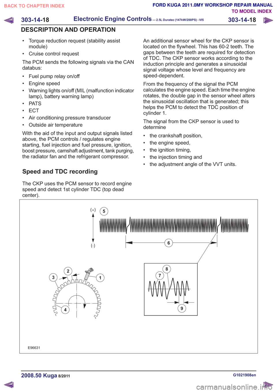
Speed and TDC recording
The CKP uses the PCM sensor to record engine
speed and detect 1st cylinder TDC (top dead
center). An additional sensor wheel for the CKP sensor is
located on the flywheel. This has 60-2 teeth. The
gaps between the teeth are required for detection
of TDC. The CKP sensor works according to the
induction principle and generates a sinusoidal
signal voltage whose level and frequency are
speed-dependent.
From the frequency of the signal the PCM
calculates the engine speed. Each time the engine
rotates, the double gap in the sensor wheel alters
the sinusoidal oscillation that is generated; this
helps the PCM to detect the TDC position of
cylinder 1.
The signal from the CKP sensor is used to
determine
• the crankshaft position,
• the engine speed,
• the ignition timing,
• the injection timing and
• the adjustment angle of the VVT units.
2
3
4
1
9
7
8
6
5
2
3
4
1
9
7
8
6
5
E96631
G1021908en2008.50 Kuga8/2011
303-14-
18
Electronic Engine Controls— 2.5L Duratec (147kW/200PS) - VI5303-14-
18
DESCRIPTION AND OPERATION
TO MODEL INDEX
BACK TO CHAPTER INDEX
FORD KUGA 2011.0MY WORKSHOP REPAIR MANUAL
Page 1796 of 2057
current value is reached. The PCM then
permanently connects the heating element to earth.
The catalyst monitor sensor is used by the PCM
to measure the oxygen content in the exhaust gas
in the TWC. If all the conditions for catalyst
diagnostics are met, based on this information the
PCM can check that the TWC is working
satisfactorily. The information is also used to
improve the air/fuel mixture adjustment.
The catalyst monitor sensor is similar in function
to an HO2S. The signal transmitted by the catalyst
monitor sensor changes sharply if the oxygen
content in the exhaust gas changes. For this
reason, catalyst monitor sensors are also called
"jump lambda sensors".
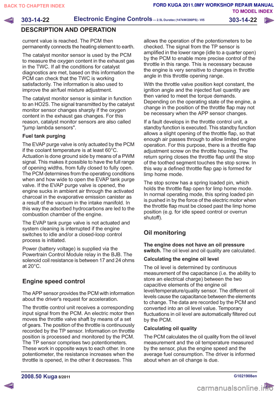
Fuel tank purging
The EVAP purge valve is only actuated by the PCM
if the coolant temperature is at least 60°C.
Actuation is done ground side by means of a PWM
signal. This makes it possible to have the full range
of opening widths, from fully closed to fully open.
The PCM determines from the operating conditions
when and how wide to open the EVAP tank purge
valve. If the EVAP purge valve is opened, the
engine sucks in ambient air through the activated
charcoal in the evaporative emission canister as
a result of the vacuum in the intake manifold. In
this way the adsorbed hydrocarbons are led to the
combustion chamber of the engine.
The EVAP tank purge valve is not actuated and
system cleaning is interrupted if the engine
switches to idle and/or a closed-loop control
process is initiated.
Power (battery voltage) is supplied via the
Powertrain Control Module relay in the BJB. The
solenoid coil resistance is between 17 and 24 ohms
at 20°C.
Engine speed control
The APP sensor provides the PCM with information
about the driver's request for acceleration.
The throttle control unit receives a corresponding
input signal from the PCM. An electric motor then
moves the throttle valve shaft by means of a set
of gears. The position of the throttle is continuously
recorded by the TP sensor. Information on throttle
position is processed and monitored by the PCM.
The TP sensor comprises two potentiometers.
These work in opposite ways to each other. In one
potentiometer, the resistance increases when the
throttle is opened, in the other it decreases. Thisallows the operation of the potentiometers to be
checked. The signal from the TP sensor is
amplified in the lower range (idle to a quarter open)
by the PCM to enable more precise control of the
throttle in this range. This is necessary because
the engine is very sensitive to changes in throttle
angle in this throttle opening range.
With the throttle valve position kept constant, the
ignition angle and the injected fuel quantity are
then varied to meet the torque demands.
Depending on the operating state of the engine, a
change in the position of the throttle flap may not
be necessary when the APP sensor changes.
If a fault develops in the throttle control unit, a
standby function is executed. This standby function
allows a slight opening of the throttle flap, so that
enough air passes through to allow limited engine
operation. For this purpose, there is a throttle flap
adjustment screw on the throttle housing. The
return spring closes the throttle flap until the stop
of the toothed segment touches the stop screw. In
this way a defined throttle flap gap is formed for
limp home mode.
The stop screw has a spring loaded pin, which
holds the throttle flap open for limp home mode.
In normal operating mode, this spring loaded pin
is pushed in by the force of the electric motor when
the throttle flap must be closed past the limp home
position (e.g. for idle speed control or overrun
shutoff).
Oil monitoring
The engine does not have an oil pressure
switch.
The oil level and oil quality are calculated.
Calculating the engine oil level
The oil level is determined by continuous
measurement of the capacitance (i.e. the ability to
store an electrical charge) between the two
capacitive elements of the engine oil
level/temperature/quality sensor. The different oil
levels cause the capacitance between the elements
to change. The data are recorded by the PCM and
converted into an oil level value. Temporary
fluctuations in oil level are automatically filtered out
by the PCM.
Calculating oil quality
The PCM calculates the oil quality from the oil level
measurement and the oil temperature measured
by the sensor, plus the engine speed and the
average fuel consumption. The driver is informed
about when an oil change is due.
G1021908en2008.50 Kuga8/2011
303-14- 22
Electronic Engine Controls— 2.5L Duratec (147kW/200PS) - VI5303-14-
22
DESCRIPTION AND OPERATION
TO MODEL INDEX
BACK TO CHAPTER INDEX
FORD KUGA 2011.0MY WORKSHOP REPAIR MANUAL