2011 FORD KUGA automatic
[x] Cancel search: automaticPage 2025 of 2057
Electronic Leak Detection
1.Refer to: Air Conditioning (A/C) System Health
and Safety Precautions (100-00 General
Information, Description and Operation).
2. WARNINGS:
Before starting leak detection, make
sure that the area where it is to be done
is well ventilated. If the surrounding air
is contaminated with refrigerant gas, the
leak detector will indicate this gas all
the time. Odors from other chemicals
such as antifreeze, diesel fuel, disc
brake cleaner, or other cleaning
solvents can cause the same problem.
Prevent air movement while performing
leak detection.
The refrigerant identification equipment
must be used before attaching the
manifold gauge set. Otherwise the
manifold gauge set may become
contaminated. Contaminated refrigerant
must be disposed of as special waste.
Follow the manufacturer's instructions
when working with the service unit.
NOTE: At 24°C with the engine switched off,
both manifold gauges should show 4.1 to 5.5
bar.
Attach the manifold gauge set to the service
gauge port valves.
3. For the leak test, close the manual valves on
the gauge set.
4. If little or no pressure is indicated, charge the
system with approx. 300g of refrigerant. Refer
to: Air Conditioning System - Evacuate and
Refill.
5. Use the R-134a Automatic Calibration Halogen
Leak Detector to leak test the refrigerant system.
Follow the instructions included with leak
detector for handling and operation techniques.
6. If any leak is found, extract the refrigerant under
suction. Refer to: Air Conditioning System -
Evacuate and Refill.
G549836en2008.50 Kuga8/2011
412-00- 14
Climate Control System - General Information
412-00- 14
GENERAL PROCEDURES
TO MODEL INDEX
BACK TO CHAPTER INDEX
FORD KUGA 2011.0MY WORKSHOP REPAIR MANUAL
Page 2026 of 2057
Fluorescent Dye Leak Detection
General EquipmentUV Leak Detector
1. Refer to: Air Conditioning (A/C) System Health
and Safety Precautions (100-00 General
Information, Description and Operation).
2. NOTE: Some vehicles may have signs of
refrigerant oil at the spring lock couplers. The
cause of this may be a procedure used in
production before installation of the fittings in
order to assist their assembly. When a spring
lock coupler is suspected of leaking, always
wipe the fitting clean and verify the leak with
R-134a Automatic Calibration Halogen Leak
Detector.
NOTE: The exact location of leaks can be
pinpointed by the bright yellow - green glow of
the tracer dye. Since more than one leak can
exist, always inspect each component.
• Locate the leaks. Check all components, fittings and lines of the A/C system for leaks.
General Equipment: UV Leak Detector
3. After the leak is found and rectified, remove any
traces of dye with a general purpose solvent.
4. Check the repair by operating the system for
some minutes and inspecting with the UV lamp
again.
G1065493en2008.50 Kuga8/2011
412-00- 15
Climate Control System - General Information
412-00- 15
GENERAL PROCEDURES
TO MODEL INDEX
BACK TO CHAPTER INDEX
FORD KUGA 2011.0MY WORKSHOP REPAIR MANUAL
Page 2028 of 2057

SECTION 412-01 Climate Control
VEHICLE APPLICATION:2008.50 Kuga
PA G E
CONTENTS
SPECIFICATIONS
412-01-3
Specifications ........................................................................\
..............................................
DESCRIPTION AND OPERATION 412-01-4
Climate Control (Component Location) ........................................................................\
......
412-01-10
Climate Control (Overview) ........................................................................\
........................
412-01-10
Pollen filter ........................................................................\
..................................................
412-01-10
Heat exchanger ........................................................................\
..........................................
412-01-10
Evaporator assembly ........................................................................\
..................................
412-01-10
Blower motor ........................................................................\
..............................................
412-01-11
Fault Memory Interrogation without diagnostics unit - vehicles with automatic temperature
control ........................................................................\
.......................................................
412-01-11
Switch over from Celsius to Fahrenheit ........................................................................\
......
412-01-12
Climate Control (System Operation and Component Description) .....................................
412-01-12
System Diagram ........................................................................\
.........................................
412-01-19
System Operation ........................................................................\
.......................................
412-01-19
Climate control housing ........................................................................\
..........................
412-01-22
Climate control ........................................................................\
........................................
412-01-24
Component Description ........................................................................\
..............................
412-01-24
Air conditioning compressor ........................................................................\
...................
412-01-24
Pollen filter ........................................................................\
..............................................
412-01-24
Control assembly, climate control - vehicles with manual temperature control ..............
412-01-25
Control assembly, climate control - vehicles with automatic temperature control ...........
412-01-25
Control assembly, climate control - vehicles with DVD navigation system with a touch
screen........................................................................\
................................................... 412-01-25
Climate control module - vehicles with DVD navigation system with a touch screen.....
412-01-25
Sun sensor - vehicles with automatic temperature control .............................................
412-01-26
In-vehicle temperature sensor ........................................................................\
................
412-01-26
Ambient temperature sensor ........................................................................\
..................
412-01-26
Blower motor ........................................................................\
...........................................
412-01-26
Blower control module - vehicles equipped with automatic temperature control ............
REMOVAL AND INSTALLATION 412-01-28
(34 626 4)
Air Conditioning (A/C) Compressor — 2.5L Duratec (147kW/200PS) - VI5 ....
412-01-29
Air Conditioning (A/C) Compressor to Condenser Discharge Line .....................................
412-01-30
Air Conditioning (A/C) Compressor to Condenser Discharge Line — 2.5L Duratec
(147kW/200PS) - VI5 ........................................................................\
................................
412-01-31
Condenser ........................................................................\
..................................................
412-01-35
Clutch and Clutch Field Coil........................................................................\
.......................
412-01-36
Pollen Filter — RHD........................................................................\
...................................
412-01-37
(34
374 0)
Blower Motor — RHD ........................................................................\
.............
412-01-40
(34 382 0)
Blower Motor Resistor — Vehicles With: Manual Temperature Control, RHD .
412-01-41
(34 382 0)
Blower Motor Resistor — Vehicles With: Dual Automatic Temperature
Control ........................................................................\
..................................
412-01- 1
Climate Control
412-01- 1
.
TO MODEL INDEX
BACK TO CHAPTER INDEX
PAGE 1 OF 2 FORD KUGA 2011.0MY WORKSHOP REPAIR MANUAL
Page 2029 of 2057

412-01-42
Heater Core and Evaporator Core Housing .......................................................................
412-01-45
(34 364 0)
Heater Core — RHD ........................................................................\
...............
412-01-53
Suction Accumulator ........................................................................\
...................................
412-01-56
Suction Accumulator to Air Conditioning (A/C) Compressor Line ......................................
412-01-57
Suction Accumulator to Air Conditioning (A/C) Compressor Line — 2.5L Duratec
(147kW/200PS) - VI5 ........................................................................\
................................
412-01-58
Low-Pressure Cutoff Switch ........................................................................\
.......................
412-01-59
High-Pressure Cutoff Switch ........................................................................\
.......................
412-01-60
Evaporator ........................................................................\
..................................................
412-01-62
Evaporator Outlet Line ........................................................................\
................................
412-01-65
Evaporator Core Orifice ........................................................................\
..............................
412-01-68
Condenser to Evaporator Line........................................................................\
....................
412-01-71
(34 300 0)
Climate Control Assembly — Vehicles With: Manual Temperature Control ....
412-01-72
(34 300 0)
Climate Control Assembly — Vehicles With: Automatic Temperature Control .
412-01-73
(34 485 4)
Footwell Air Discharge Temperature Sensor ..................................................
412-01-74
Center Register Air Discharge Temperature Sensor ..........................................................
412-01-75
In-Vehicle Temperature Sensor ........................................................................\
..................
412-01-76
(34 676 0)
Ambient Air Temperature Sensor ...................................................................
412-01-77
(34 665 0)
Sunload Sensor ........................................................................\
......................
412-01-78
(34 591 0)
Footwell Vent/Duct Blend Door Actuator — RHD ...........................................
412-01-79
(34 606 0)
Air Inlet Blend Door Actuator ........................................................................\
..
412-01-80
(34 608 0)
Driver Side Temperature Blend Door Actuator ...............................................
412-01-81
(34 608 0)
Passenger Side Temperature Blend Door Actuator .......................................
412-01-82
(34 591 0)
Defrost Vent/Register Blend Door Actuator — RHD ......................................
412-01-2
Climate Control
412-01- 2
.
TO MODEL INDEX
BACK TO CHAPTER INDEX
PAGE 2 OF 2 FORD KUGA 2011.0MY WORKSHOP REPAIR MANUAL
Page 2032 of 2057
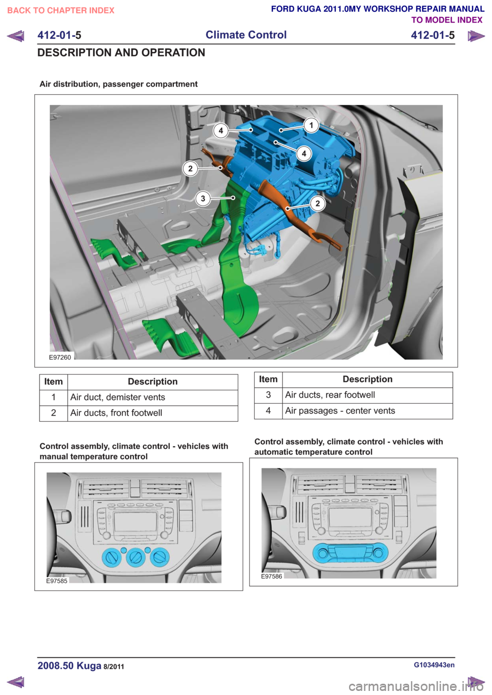
Air distribution, passenger compartment
E97260
14
2
2
3
4
Description
Item
Air duct, demister vents
1
Air ducts, front footwell
2Description
Item
Air ducts, rear footwell
3
Air passages - center vents
4
Control assembly, climate control - vehicles with
manual temperature control
E97585
Control assembly, climate control - vehicles with
automatic temperature control
E97586
G1034943en2008.50 Kuga8/2011
412-01- 5
Climate Control
412-01- 5
DESCRIPTION AND OPERATION
TO MODEL INDEX
BACK TO CHAPTER INDEX
FORD KUGA 2011.0MY WORKSHOP REPAIR MANUAL
Page 2033 of 2057
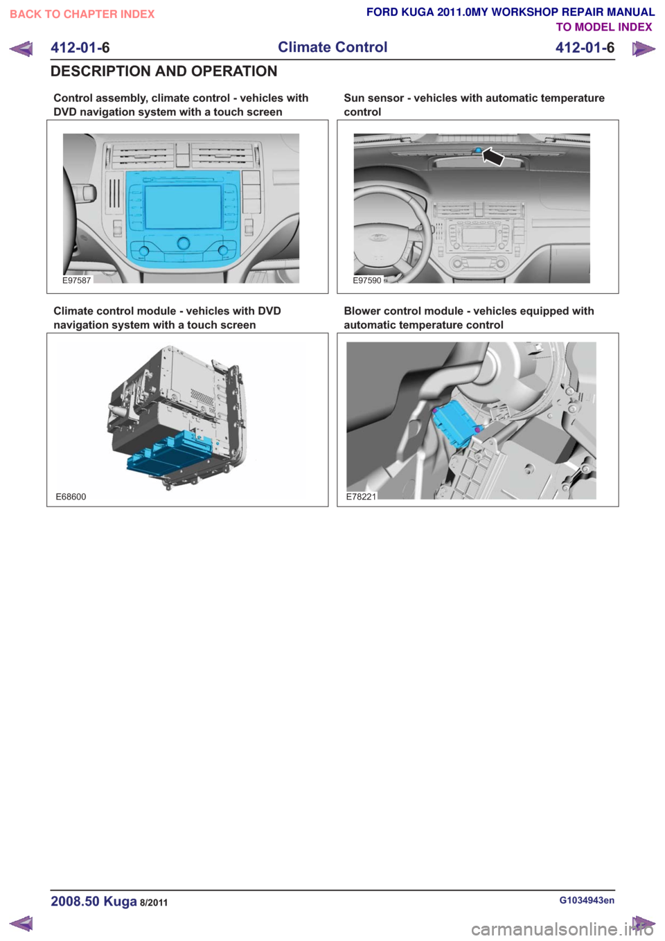
Control assembly, climate control - vehicles with
DVD navigation system with a touch screen
E97587
Climate control module - vehicles with DVD
navigation system with a touch screen
E68600
Sun sensor - vehicles with automatic temperature
control
E97590
Blower control module - vehicles equipped with
automatic temperature control
E78221
G1034943en2008.50 Kuga8/2011
412-01-6
Climate Control
412-01- 6
DESCRIPTION AND OPERATION
TO MODEL INDEX
BACK TO CHAPTER INDEX
FORD KUGA 2011.0MY WORKSHOP REPAIR MANUAL
Page 2036 of 2057
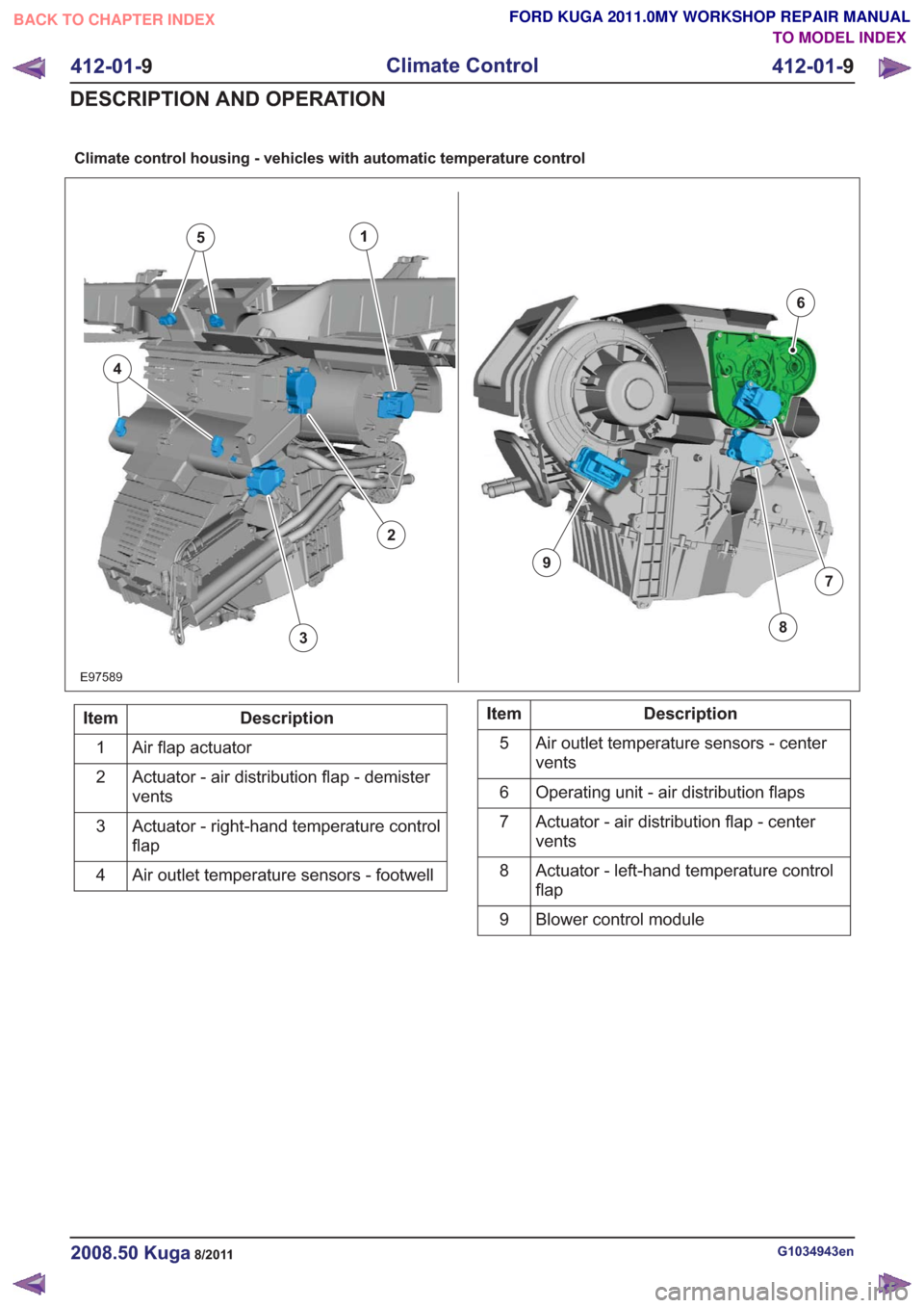
Climate control housing - vehicles with automatic temperature control
E97589
1
7
6
38
9
5
4
2
Description
Item
Air flap actuator
1
Actuator - air distribution flap - demister
vents
2
Actuator - right-hand temperature control
flap
3
Air outlet temperature sensors - footwell
4Description
Item
Air outlet temperature sensors - center
vents
5
Operating unit - air distribution flaps
6
Actuator - air distribution flap - center
vents
7
Actuator - left-hand temperature control
flap
8
Blower control module
9
G1034943en2008.50 Kuga8/2011
412-01- 9
Climate Control
412-01- 9
DESCRIPTION AND OPERATION
TO MODEL INDEX
BACK TO CHAPTER INDEX
FORD KUGA 2011.0MY WORKSHOP REPAIR MANUAL
Page 2038 of 2057
Fault Memory Interrogation without
diagnostics unit - vehicles with
automatic temperature control
NOTE:On vehicles equipped with a DVD
navigation system with touchscreen, the fault
memory can only be interrogated using the Ford
diagnostic tool.
The climate control and heating system features
a on-board diagnosis function which can detect
and store both current permanent faults as well as
intermittent faults which have occurred during
normal operation of the vehicle. It is also possible
to read out these faults via the display on the
control panel of the climate control system. To read
out the fault memory, the ignition key must be
turned to the "ON" position and the battery voltage
must be between 9 V and 16 V.
To activate the on-board diagnosis at the control
panel for the climate control system, PRESS the
"OFF" and "FOOTWELL" buttons simultaneously
for exactly 2 seconds, then PRESS "AUTO" within
1.5 seconds. The on-board diagnosis which then
starts lasts a few seconds. An animated display
appears in the display of the control panel for the
climate control system during this time. Any faults
found are displayed on both displays of the control
panel for the climate control system in the form of
trouble codes.
To read out saved errors at the control panel for
the climate control system, PRESS the "OFF" and
"FOOTWELL" buttons simultaneously for exactly
2 seconds, then PRESS "HEAD AREA" within 1.5
seconds. Any stored faults are shown on the
display of the control panel for the climate control
system and should be noted for safety reasons.
By PRESSING the "DEFROST" button, the fault
memory is cleared and diagnosis mode is ended.
To end the diagnostic mode without clearing the
DTCs, PRESS any other operating button on the
control panel for the climate control system.
To read out the software version at the control
panel for the climate control system, PRESS the
"OFF" and "FOOTWELL" buttons simultaneously
for exactly 2 seconds, then PRESS "A/C" within
1.5 seconds. The software version is shown on the
display of the control panel for the climate control
system. The output mode can be exited by
PRESSING any button on the control panel for the
climate control system.
Switch over from Celsius to Fahrenheit
The switch from Celsius to Fahrenheit is performed
on the display of the instrument cluster and is then
transmitted via the CAN bus to the module of the
two-zone air conditioning system.
G1034945en2008.50 Kuga8/2011
412-01- 11
Climate Control
412-01- 11
DESCRIPTION AND OPERATION
TO MODEL INDEX
BACK TO CHAPTER INDEX
FORD KUGA 2011.0MY WORKSHOP REPAIR MANUAL