Page 1969 of 2057
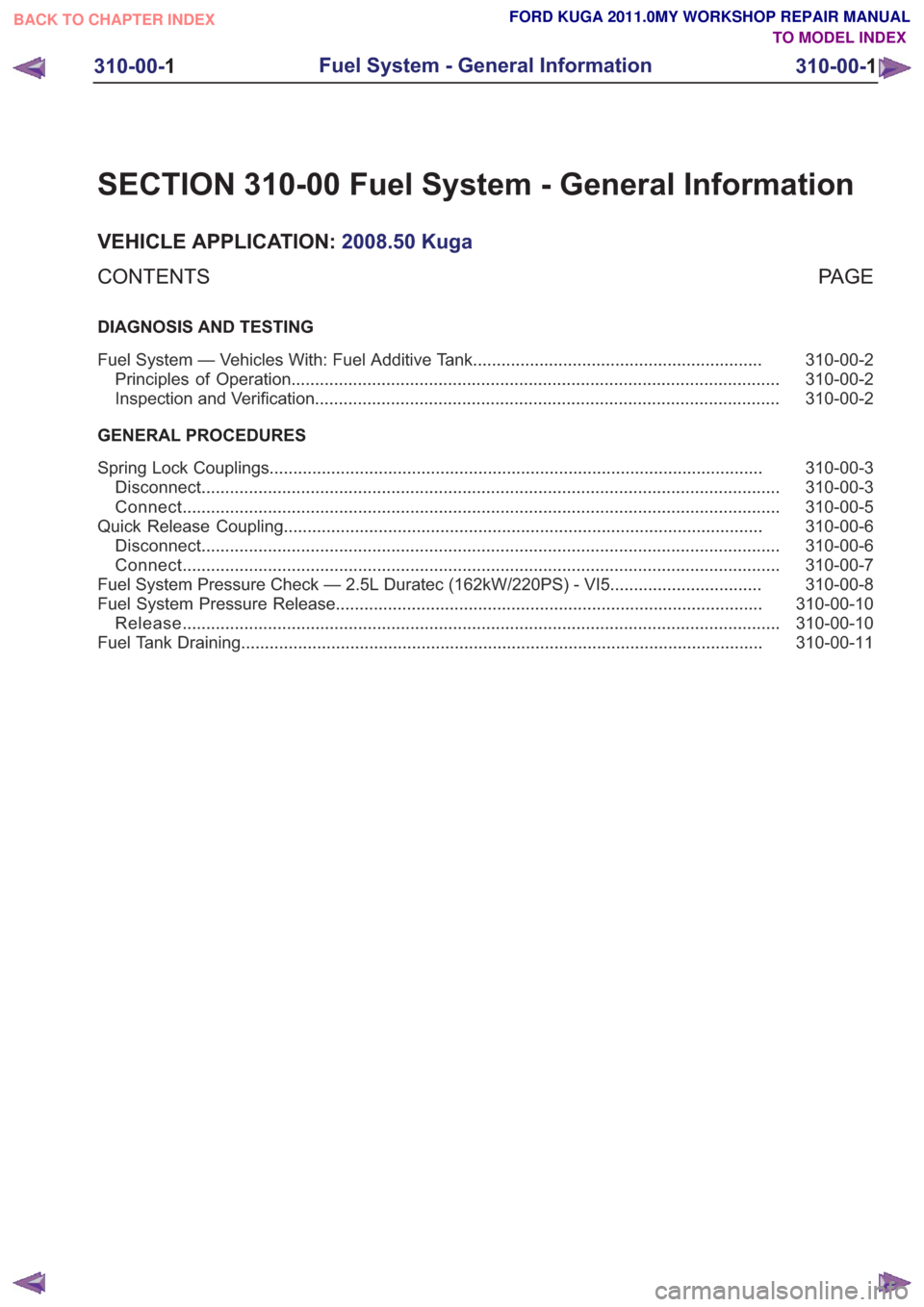
SECTION 310-00 Fuel System - General Information
VEHICLE APPLICATION:2008.50 Kuga
PA G E
CONTENTS
DIAGNOSIS AND TESTING
310-00-2
Fuel System — Vehicles With: Fuel Additive Tank .............................................................
310-00-2
Principles of Operation ........................................................................\
...............................
310-00-2
Inspection and Verification ........................................................................\
..........................
GENERAL PROCEDURES 310-00-3
Spring Lock Couplings ........................................................................\
................................
310-00-3
Disconnect ........................................................................\
..................................................
310-00-5
Connect ........................................................................\
......................................................
310-00-6
Quick Release Coupling ........................................................................\
.............................
310-00-6
Disconnect ........................................................................\
..................................................
310-00-7
Connect ........................................................................\
......................................................
310-00-8
Fuel System Pressure Check — 2.5L Duratec (162kW/220PS) - VI5 ................................
310-00-10
Fuel System Pressure Release ........................................................................\
..................
310-00-10
Release ........................................................................\
......................................................
310-00-11
Fuel Tank Draining ........................................................................\
......................................
310-00-1
Fuel System - General Information
310-00- 1
.
TO MODEL INDEX
BACK TO CHAPTER INDEX
FORD KUGA 2011.0MY WORKSHOP REPAIR MANUAL
Page 1971 of 2057
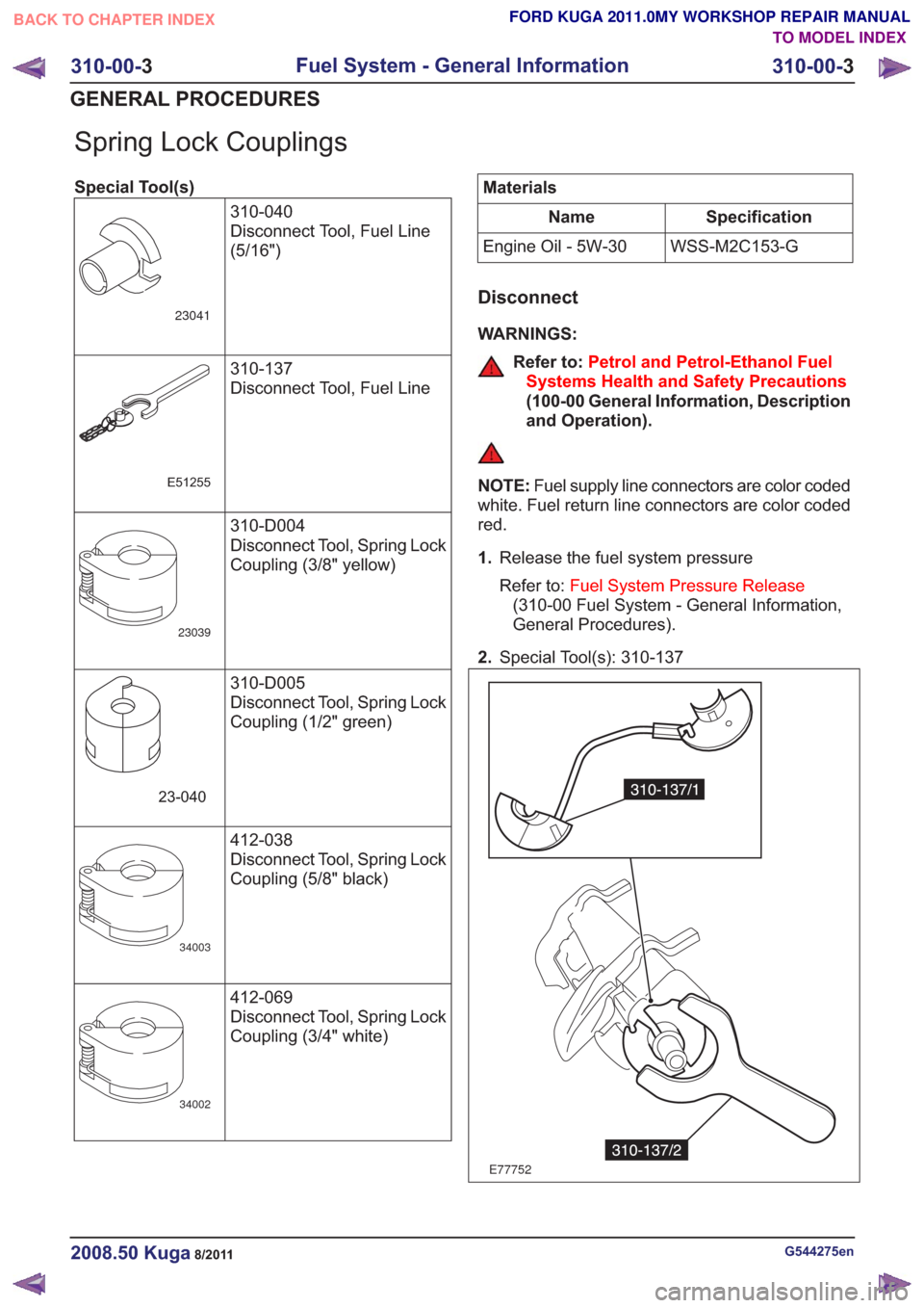
Spring Lock Couplings
Special Tool(s)310-040
Disconnect Tool, Fuel Line
(5/16")
23041
310-137
Disconnect Tool, Fuel Line
E51255
310-D004
Disconnect Tool, Spring Lock
Coupling (3/8" yellow)
23039
310-D005
Disconnect Tool, Spring Lock
Coupling (1/2" green)
23-040
412-038
Disconnect Tool, Spring Lock
Coupling (5/8" black)
34003
412-069
Disconnect Tool, Spring Lock
Coupling (3/4" white)
34002
Materials
Specification
Name
WSS-M2C153-G
Engine Oil - 5W-30
Disconnect
WARNINGS:
Refer to: Petrol and Petrol-Ethanol Fuel
Systems Health and Safety Precautions
(100-00 General Information, Description
and Operation).
NOTE: Fuel supply line connectors are color coded
white. Fuel return line connectors are color coded
red.
1. Release the fuel system pressure
Refer to: Fuel System Pressure Release
(310-00 Fuel System - General Information,
General Procedures).
2. Special Tool(s): 310-137
E77752
G544275en2008.50 Kuga8/2011
310-00- 3
Fuel System - General Information
310-00- 3
GENERAL PROCEDURES
TO MODEL INDEX
BACK TO CHAPTER INDEX
FORD KUGA 2011.0MY WORKSHOP REPAIR MANUAL
Page 1974 of 2057
Quick Release Coupling
General EquipmentFlat-bladed screwdriver
Disconnect
WARNINGS:
Refer to: Petrol and Petrol-Ethanol Fuel
Systems Health and Safety Precautions
(100-00 General Information, Description
and Operation).
NOTE: Fuel supply line connectors are color coded
white. Fuel return line connectors are color coded
red.
1. Release the fuel system pressure
Refer to: Fuel System Pressure Release
(310-00 Fuel System - General Information,
General Procedures).
2.
E71970
1 2
1
3.
E71971
3
12
4.
E71973
21
1
5.
E53517
1
2
6.
E38209
2
1
G544276en2008.50 Kuga8/2011
310-00- 6
Fuel System - General Information
310-00- 6
GENERAL PROCEDURES
TO MODEL INDEX
BACK TO CHAPTER INDEX
FORD KUGA 2011.0MY WORKSHOP REPAIR MANUAL
Page 1976 of 2057
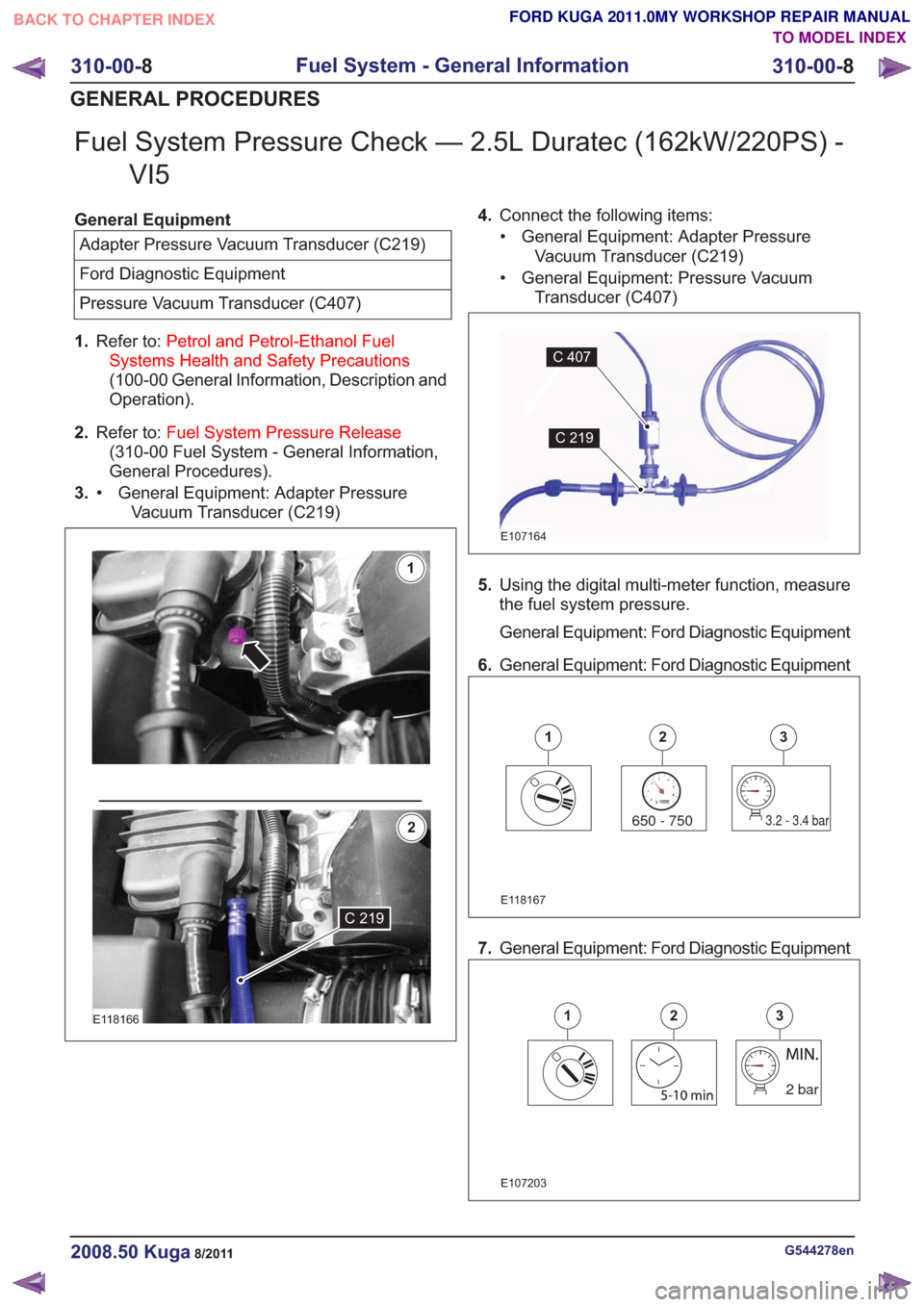
Fuel System Pressure Check — 2.5L Duratec (162kW/220PS) -VI5
General Equipment
Adapter Pressure Vacuum Transducer (C219)
Ford Diagnostic Equipment
Pressure Vacuum Transducer (C407)
1. Refer to: Petrol and Petrol-Ethanol Fuel
Systems Health and Safety Precautions
(100-00 General Information, Description and
Operation).
2. Refer to: Fuel System Pressure Release
(310-00 Fuel System - General Information,
General Procedures).
3. General Equipment: Adapter Pressure
Vacuum Transducer (C219)
•
E118166
1
2
C 219
4.
Connect the following items:
• General Equipment: Adapter Pressure Vacuum Transducer (C219)
• General Equipment: Pressure Vacuum Transducer (C407)
E107164
C 407
C219
5.Using the digital multi-meter function, measure
the fuel system pressure.
General Equipment: Ford Diagnostic Equipment
6. General Equipment: Ford Diagnostic Equipment
650 - 7503.6 - 4 bar650 - 7503.2 - 3.4 bar
123
E118167
7.General Equipment: Ford Diagnostic Equipment
2 bar2 bar
E107203
123
G544278en2008.50 Kuga8/2011
310-00- 8
Fuel System - General Information
310-00- 8
GENERAL PROCEDURES
TO MODEL INDEX
BACK TO CHAPTER INDEX
FORD KUGA 2011.0MY WORKSHOP REPAIR MANUAL
Page 1977 of 2057
8.Refer to: Fuel System Pressure Release
(310-00 Fuel System - General Information,
General Procedures).
9. Disconnect the following items:
• General Equipment: Adapter Pressure Vacuum Transducer (C219)
• General Equipment: Pressure Vacuum Transducer (C407)
E107164
C 407
C 219
10. General Equipment: Adapter Pressure
Vacuum Transducer (C219)
•
C 219C 219
1
E118168
2
G544278en2008.50 Kuga8/2011
310-00-
9
Fuel System - General Information
310-00- 9
GENERAL PROCEDURES
TO MODEL INDEX
BACK TO CHAPTER INDEX
FORD KUGA 2011.0MY WORKSHOP REPAIR MANUAL
Page 1978 of 2057
Fuel System Pressure Release
Release
1.Refer to: Petrol and Petrol-Ethanol Fuel
Systems Health and Safety Precautions
(100-00 General Information, Description and
Operation).
2. Remove the fuel pump and sender unit fuse.
3. Start the engine and allow it to idle until the
engine stalls.
4. Crank the engine for approximately five seconds
to make sure that the fuel rail pressure is
released.
5. Install the fuel pump and sender unit fuse.
G551380en2008.50 Kuga8/2011
310-00- 10
Fuel System - General Information
310-00- 10
GENERAL PROCEDURES
TO MODEL INDEX
BACK TO CHAPTER INDEX
FORD KUGA 2011.0MY WORKSHOP REPAIR MANUAL
Page 1986 of 2057
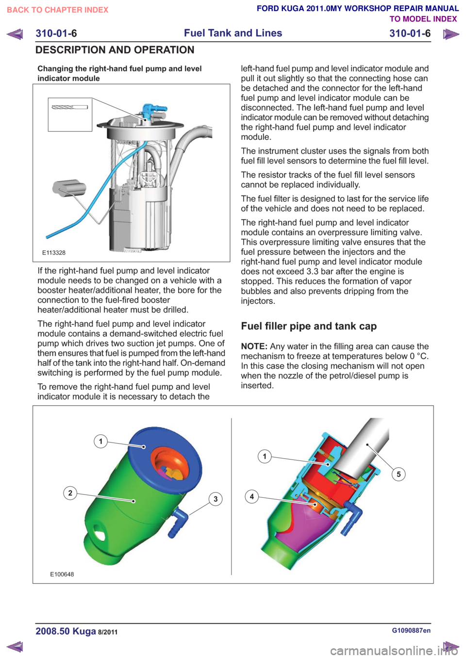
Changing the right-hand fuel pump and level
indicator module
E113328
If the right-hand fuel pump and level indicator
module needs to be changed on a vehicle with a
booster heater/additional heater, the bore for the
connection to the fuel-fired booster
heater/additional heater must be drilled.
The right-hand fuel pump and level indicator
module contains a demand-switched electric fuel
pump which drives two suction jet pumps. One of
them ensures that fuel is pumped from the left-hand
half of the tank into the right-hand half. On-demand
switching is performed by the fuel pump module.
To remove the right-hand fuel pump and level
indicator module it is necessary to detach theleft-hand fuel pump and level indicator module and
pull it out slightly so that the connecting hose can
be detached and the connector for the left-hand
fuel pump and level indicator module can be
disconnected. The left-hand fuel pump and level
indicator module can be removed without detaching
the right-hand fuel pump and level indicator
module.
The instrument cluster uses the signals from both
fuel fill level sensors to determine the fuel fill level.
The resistor tracks of the fuel fill level sensors
cannot be replaced individually.
The fuel filter is designed to last for the service life
of the vehicle and does not need to be replaced.
The right-hand fuel pump and level indicator
module contains an overpressure limiting valve.
This overpressure limiting valve ensures that the
fuel pressure between the injectors and the
right-hand fuel pump and level indicator module
does not exceed 3.3 bar after the engine is
stopped. This reduces the formation of vapor
bubbles and also prevents dripping from the
injectors.
Fuel filler pipe and tank cap
NOTE:
Any water in the filling area can cause the
mechanism to freeze at temperatures below 0 °C.
In this case the closing mechanism will not open
when the nozzle of the petrol/diesel pump is
inserted.
43
1
2
1
5
43
1
2
1
5
E100648
G1090887en2008.50 Kuga8/2011
310-01- 6
Fuel Tank and Lines
310-01- 6
DESCRIPTION AND OPERATION
TO MODEL INDEX
BACK TO CHAPTER INDEX
FORD KUGA 2011.0MY WORKSHOP REPAIR MANUAL
Page 2018 of 2057
Air Conditioning (A/C) System Recovery, Evacuation and Charging
General EquipmentAir Conditioning Service Unit
Automatic Calibration Halogen Leak Detector
Electronic Leak Detector
Refrigerant Identification Equipment
UV Leak Detector
1. Refer to: Air Conditioning (A/C) System Health
and Safety Precautions (100-00 General
Information, Description and Operation).
2.
E100846
x4
3. CAUTION: The refrigerant analyzer must be used before recovery, otherwise the
refrigerant center may become
contaminated. Contaminated refrigerant
must be disposed of as hazardous
waste. Always follow the manufacturer's
instructions when using the refrigerant
center and the refrigerant analyzer.
Unscrew and remove the protective caps from
the A/C charging connections.
General Equipment: Air Conditioning Service Unit
General Equipment: Refrigerant Identification Equipment 4.
Low-pressure connection
1.
2. High-pressure connection
2
E51608
1
5. Connect the service unit lines to the filling
connection of the air conditioning system.
VFE0031288
6.Drain the air conditioning system via the
low-pressure port in accordance with the service
unit manufacturer instructions.
7. CAUTION: Make sure that the specified amount of refrigerant oil is added.
NOTE:This step is only required when installing
a new component.
Fill up with refrigerant oil.
Refer to: Specifications (412-00 Climate Control
System - General Information, Specifications).
Refer to: Refrigerant Oil Adding (412-00 Climate
Control System - General Information, General
Procedures).
8. Evacuate the air conditioning system in
accordance with the service unit manufacturer
instructions.
9. NOTE: The system is leak-tight if the pressure
increase does not exceed 20 mbar.
G1022208en2008.50 Kuga8/2011
412-00- 7
Climate Control System - General Information
412-00- 7
GENERAL PROCEDURES
TO MODEL INDEX
BACK TO CHAPTER INDEX
FORD KUGA 2011.0MY WORKSHOP REPAIR MANUAL