2011 FORD KUGA Index
[x] Cancel search: IndexPage 2021 of 2057
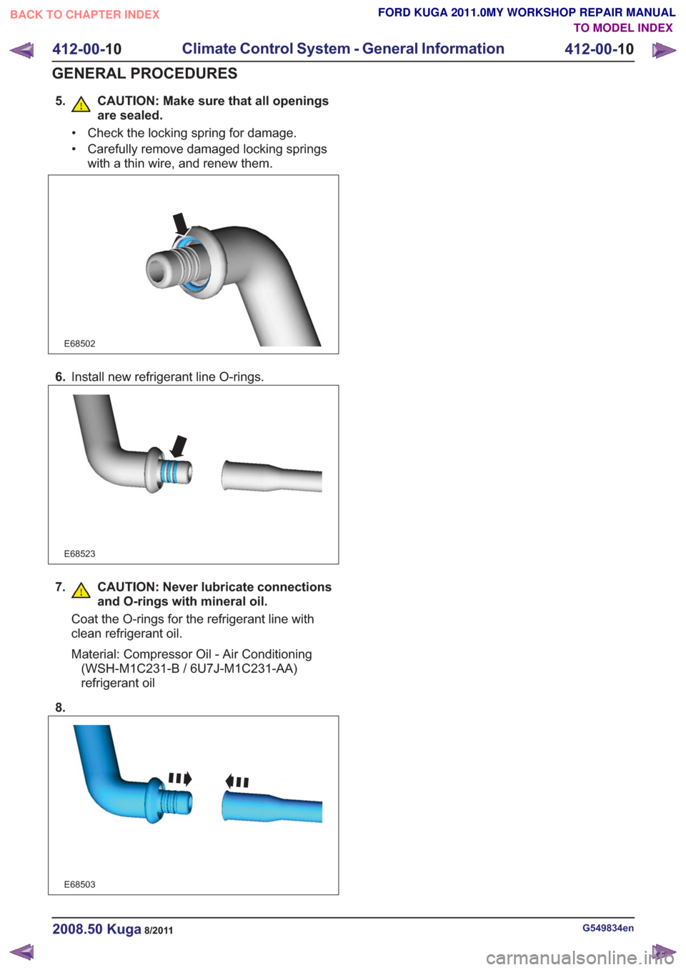
5. CAUTION: Make sure that all openingsare sealed.
• Check the locking spring for damage.
• Carefully remove damaged locking springswith a thin wire, and renew them.
E68502
6.Install new refrigerant line O-rings.
E68523
7. CAUTION: Never lubricate connections
and O-rings with mineral oil.
Coat the O-rings for the refrigerant line with
clean refrigerant oil.
Material: Compressor Oil - Air Conditioning(WSH-M1C231-B / 6U7J-M1C231-AA)
refrigerant oil
8.
E68503
G549834en2008.50 Kuga8/2011
412-00- 10
Climate Control System - General Information
412-00- 10
GENERAL PROCEDURES
TO MODEL INDEX
BACK TO CHAPTER INDEX
FORD KUGA 2011.0MY WORKSHOP REPAIR MANUAL
Page 2022 of 2057
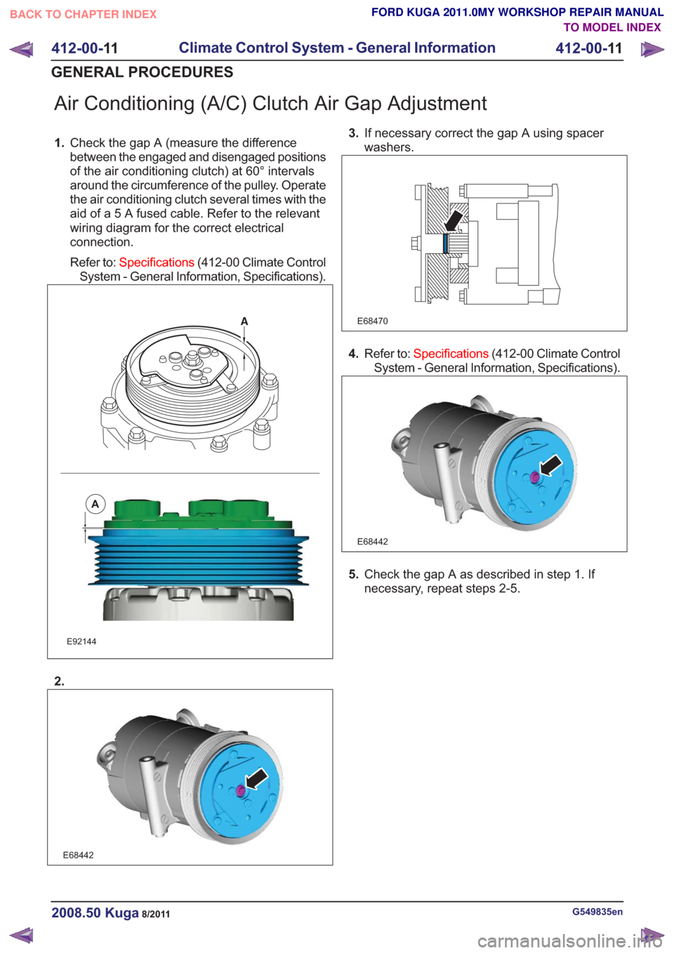
Air Conditioning (A/C) Clutch Air Gap Adjustment
1.Check the gap A (measure the difference
between the engaged and disengaged positions
of the air conditioning clutch) at 60° intervals
around the circumference of the pulley. Operate
the air conditioning clutch several times with the
aid of a 5 A fused cable. Refer to the relevant
wiring diagram for the correct electrical
connection.
Refer to: Specifications (412-00 Climate Control
System - General Information, Specifications).
E92144
A
2.
E68442
3. If necessary correct the gap A using spacer
washers.
E68470
4.Refer to: Specifications (412-00 Climate Control
System - General Information, Specifications).
E68442
5. Check the gap A as described in step 1. If
necessary, repeat steps 2-5.
G549835en2008.50 Kuga8/2011
412-00- 11
Climate Control System - General Information
412-00- 11
GENERAL PROCEDURES
TO MODEL INDEX
BACK TO CHAPTER INDEX
FORD KUGA 2011.0MY WORKSHOP REPAIR MANUAL
Page 2023 of 2057
Refrigerant Oil Adding
CAUTION: Collect the refrigerant oil in a
clean measuring cylinder.
1. NOTE: This step only needs to be carried out
when removing the A/C compressor.
NOTE: Rotate the compressor shaft at least 6
to 8 turns when draining the refrigerant oil.
Drain the refrigerant oil from the defective A/C
compressor and dispose of it.
2. CAUTIONS:
The refrigerant oil top-up quantity must
not exceed the refrigerant oil fill
quantity.
If other A/C components are being
renewed in addition to the A/C
compressor, there is no need to top up
with additional refrigerant oil, apart from
filling the compressor.
Top up with the calculated quantity of new
refrigerant oil. See:Specifications(412-00
Heating, Ventilation, Air-Conditioning - General
information, Specifications).
G549839en2008.50 Kuga8/2011
412-00- 12
Climate Control System - General Information
412-00- 12
GENERAL PROCEDURES
TO MODEL INDEX
BACK TO CHAPTER INDEX
FORD KUGA 2011.0MY WORKSHOP REPAIR MANUAL
Page 2024 of 2057
Contaminated Refrigerant Handling
1. CAUTION: Any R134a or R12 refrigerantwhich is contaminated with unsuitable
refrigerant should be extracted only by
means of a suitable servicing unit
designed for the purpose of collecting
and storing contaminated refrigerant,
so that the spread to other vehicles can
be prevented.
Use refrigerant identification equipment to check
that there is contaminated refrigerant in the air
conditioning system.
2. Inform the customer about the additional costs
involved to repair the system because of the
contamination.
3. Extract the contaminated refrigerant.
G549840en2008.50 Kuga8/2011
412-00- 13
Climate Control System - General Information
412-00- 13
GENERAL PROCEDURES
TO MODEL INDEX
BACK TO CHAPTER INDEX
FORD KUGA 2011.0MY WORKSHOP REPAIR MANUAL
Page 2025 of 2057
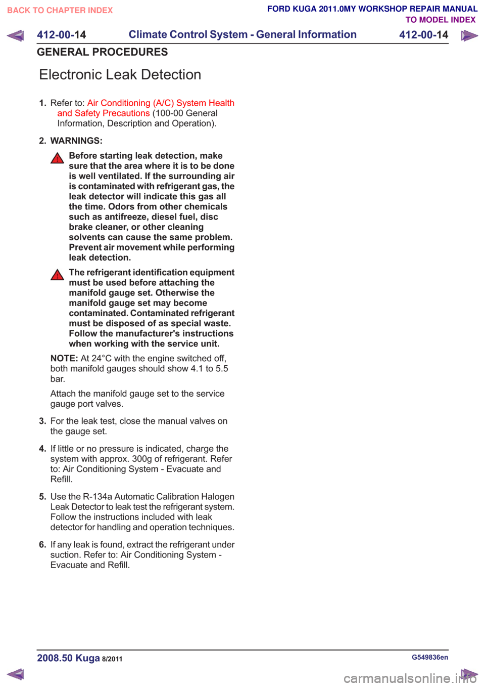
Electronic Leak Detection
1.Refer to: Air Conditioning (A/C) System Health
and Safety Precautions (100-00 General
Information, Description and Operation).
2. WARNINGS:
Before starting leak detection, make
sure that the area where it is to be done
is well ventilated. If the surrounding air
is contaminated with refrigerant gas, the
leak detector will indicate this gas all
the time. Odors from other chemicals
such as antifreeze, diesel fuel, disc
brake cleaner, or other cleaning
solvents can cause the same problem.
Prevent air movement while performing
leak detection.
The refrigerant identification equipment
must be used before attaching the
manifold gauge set. Otherwise the
manifold gauge set may become
contaminated. Contaminated refrigerant
must be disposed of as special waste.
Follow the manufacturer's instructions
when working with the service unit.
NOTE: At 24°C with the engine switched off,
both manifold gauges should show 4.1 to 5.5
bar.
Attach the manifold gauge set to the service
gauge port valves.
3. For the leak test, close the manual valves on
the gauge set.
4. If little or no pressure is indicated, charge the
system with approx. 300g of refrigerant. Refer
to: Air Conditioning System - Evacuate and
Refill.
5. Use the R-134a Automatic Calibration Halogen
Leak Detector to leak test the refrigerant system.
Follow the instructions included with leak
detector for handling and operation techniques.
6. If any leak is found, extract the refrigerant under
suction. Refer to: Air Conditioning System -
Evacuate and Refill.
G549836en2008.50 Kuga8/2011
412-00- 14
Climate Control System - General Information
412-00- 14
GENERAL PROCEDURES
TO MODEL INDEX
BACK TO CHAPTER INDEX
FORD KUGA 2011.0MY WORKSHOP REPAIR MANUAL
Page 2026 of 2057
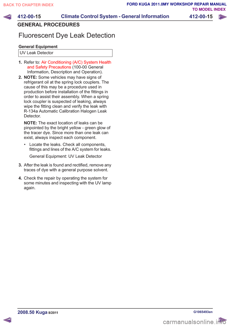
Fluorescent Dye Leak Detection
General EquipmentUV Leak Detector
1. Refer to: Air Conditioning (A/C) System Health
and Safety Precautions (100-00 General
Information, Description and Operation).
2. NOTE: Some vehicles may have signs of
refrigerant oil at the spring lock couplers. The
cause of this may be a procedure used in
production before installation of the fittings in
order to assist their assembly. When a spring
lock coupler is suspected of leaking, always
wipe the fitting clean and verify the leak with
R-134a Automatic Calibration Halogen Leak
Detector.
NOTE: The exact location of leaks can be
pinpointed by the bright yellow - green glow of
the tracer dye. Since more than one leak can
exist, always inspect each component.
• Locate the leaks. Check all components, fittings and lines of the A/C system for leaks.
General Equipment: UV Leak Detector
3. After the leak is found and rectified, remove any
traces of dye with a general purpose solvent.
4. Check the repair by operating the system for
some minutes and inspecting with the UV lamp
again.
G1065493en2008.50 Kuga8/2011
412-00- 15
Climate Control System - General Information
412-00- 15
GENERAL PROCEDURES
TO MODEL INDEX
BACK TO CHAPTER INDEX
FORD KUGA 2011.0MY WORKSHOP REPAIR MANUAL
Page 2027 of 2057
Vacuum Leak Detection
1.Carry out the air conditioning (A/C) system
recovery procedure.
Refer to: Air Conditioning (A/C) System
Recovery, Evacuation and Charging (412-00
Climate Control System - General Information,
General Procedures).
G1065495en2008.50 Kuga8/2011
412-00- 16
Climate Control System - General Information
412-00- 16
GENERAL PROCEDURES
TO MODEL INDEX
BACK TO CHAPTER INDEX
FORD KUGA 2011.0MY WORKSHOP REPAIR MANUAL
Page 2028 of 2057
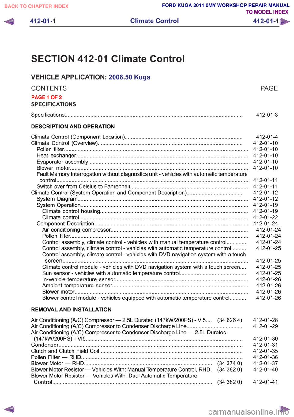
SECTION 412-01 Climate Control
VEHICLE APPLICATION:2008.50 Kuga
PA G E
CONTENTS
SPECIFICATIONS
412-01-3
Specifications ........................................................................\
..............................................
DESCRIPTION AND OPERATION 412-01-4
Climate Control (Component Location) ........................................................................\
......
412-01-10
Climate Control (Overview) ........................................................................\
........................
412-01-10
Pollen filter ........................................................................\
..................................................
412-01-10
Heat exchanger ........................................................................\
..........................................
412-01-10
Evaporator assembly ........................................................................\
..................................
412-01-10
Blower motor ........................................................................\
..............................................
412-01-11
Fault Memory Interrogation without diagnostics unit - vehicles with automatic temperature
control ........................................................................\
.......................................................
412-01-11
Switch over from Celsius to Fahrenheit ........................................................................\
......
412-01-12
Climate Control (System Operation and Component Description) .....................................
412-01-12
System Diagram ........................................................................\
.........................................
412-01-19
System Operation ........................................................................\
.......................................
412-01-19
Climate control housing ........................................................................\
..........................
412-01-22
Climate control ........................................................................\
........................................
412-01-24
Component Description ........................................................................\
..............................
412-01-24
Air conditioning compressor ........................................................................\
...................
412-01-24
Pollen filter ........................................................................\
..............................................
412-01-24
Control assembly, climate control - vehicles with manual temperature control ..............
412-01-25
Control assembly, climate control - vehicles with automatic temperature control ...........
412-01-25
Control assembly, climate control - vehicles with DVD navigation system with a touch
screen........................................................................\
................................................... 412-01-25
Climate control module - vehicles with DVD navigation system with a touch screen.....
412-01-25
Sun sensor - vehicles with automatic temperature control .............................................
412-01-26
In-vehicle temperature sensor ........................................................................\
................
412-01-26
Ambient temperature sensor ........................................................................\
..................
412-01-26
Blower motor ........................................................................\
...........................................
412-01-26
Blower control module - vehicles equipped with automatic temperature control ............
REMOVAL AND INSTALLATION 412-01-28
(34 626 4)
Air Conditioning (A/C) Compressor — 2.5L Duratec (147kW/200PS) - VI5 ....
412-01-29
Air Conditioning (A/C) Compressor to Condenser Discharge Line .....................................
412-01-30
Air Conditioning (A/C) Compressor to Condenser Discharge Line — 2.5L Duratec
(147kW/200PS) - VI5 ........................................................................\
................................
412-01-31
Condenser ........................................................................\
..................................................
412-01-35
Clutch and Clutch Field Coil........................................................................\
.......................
412-01-36
Pollen Filter — RHD........................................................................\
...................................
412-01-37
(34
374 0)
Blower Motor — RHD ........................................................................\
.............
412-01-40
(34 382 0)
Blower Motor Resistor — Vehicles With: Manual Temperature Control, RHD .
412-01-41
(34 382 0)
Blower Motor Resistor — Vehicles With: Dual Automatic Temperature
Control ........................................................................\
..................................
412-01- 1
Climate Control
412-01- 1
.
TO MODEL INDEX
BACK TO CHAPTER INDEX
PAGE 1 OF 2 FORD KUGA 2011.0MY WORKSHOP REPAIR MANUAL