2011 FORD KUGA wheel alignment
[x] Cancel search: wheel alignmentPage 1204 of 2057
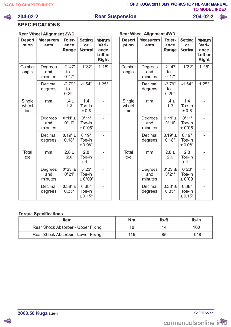
Rear Wheel Alignment 2WD
MaximumVari-
ance
Left or Right
Setting
or
Nominal
Toler-
ance
Range
Measurem
ents
Descri
ption
1°15'
-1°32'
-2°47'
to -
0°17'
Degrees
and
minutes
Camber
angle
1.25°
-1.54°
-2.79°
to -
0.29°
Decimal
degrees
-1.4
Toe-in ±0.6
1.4 ±
1.3
mm
Single
wheel toe
-
0°11'
Toe-in
± 0°05'
0°11' ±
0°10'
Degrees
and
minutes
-
0.19°
Toe-in
± 0.08°
0.19° ±
0.18°
Decimal
degrees
-2.8
Toe-in ±1.1
2.8 ±
2.6
mm
To t a l
toe
-
0°23'
Toe-in
± 0°09'
0°23' ±
0°21'
Degrees
and
minutes
-
0.38°
Toe-in
± 0.15°
0.38° ±
0.35°
Decimal
degrees Rear Wheel Alignment 4WDMaximum
Vari-
ance
Left or Right
Setting
or
Nominal
Toler-
ance
Range
Measurem
ents
Descri
ption
1°15'
-1°32'
-2°.47'
to -
0°17'
Degrees
and
minutes
Camber
angle
1.25°
-1.54°
-2.79°
to -
0.29°
Decimal
degrees
-1.4
Toe-in ±0.6
1.4 ±
1.3
mm
Single
wheel toe
-
0°11'
Toe-in
± 0°05'
0°11' ±
0°10'
Degrees
and
minutes
-
0.19°
Toe-in
± 0.08°
0.19° ±
0.18°
Decimal
degrees
-2.8
Toe-in ±1.1
2.8 ±
2.6
mm
To t a l
toe
-
0°23'
Toe-in
± 0°09'
0°23' ±
0°21'
Degrees
and
minutes
-
0.38°
Toe-in
± 0.15°
0.38° ±
0.35°
Decimal
degrees
Torque Specifications
lb-in
lb-ft
Nm
Item
160
14
18
Rear Shock Absorber - Upper Fixing
1018
85
11 5
Rear Shock Absorber - Lower Fixing
G1000727en2008.50 Kuga8/2011
204-02- 2
Rear Suspension
204-02- 2
SPECIFICATIONS
TO MODEL INDEX
BACK TO CHAPTER INDEX
FORD KUGA 2011.0MY WORKSHOP REPAIR MANUAL
Page 1233 of 2057
Wheels and Tires
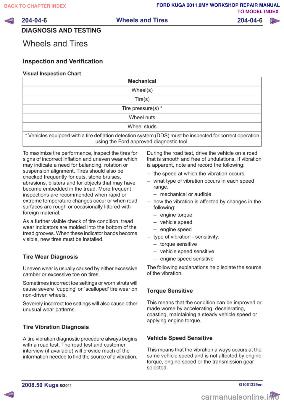
Inspection and Verification
Visual Inspection Chart
MechanicalWheel(s)Tire(s)
Tire pressure(s) * Wheel nuts
Wheel studs
* Vehicles equipped with a tire deflation detection system (DDS) must be inspected for correct operation using the Ford approved diagnostic tool.
To maximize tire performance, inspect the tires for
signs of incorrect inflation and uneven wear which
may indicate a need for balancing, rotation or
suspension alignment. Tires should also be
checked frequently for cuts, stone bruises,
abrasions, blisters and for objects that may have
become embedded in the tread. More frequent
inspections are recommended when rapid or
extreme temperature changes occur or when road
surfaces are rough or occasionally littered with
foreign material.
As a further visible check of tire condition, tread
wear indicators are molded into the bottom of the
tread grooves. When these indicator bands become
visible, new tires must be installed.
Tire Wear Diagnosis
Uneven wear is usually caused by either excessive
camber or excessive toe on tires.
Sometimes incorrect toe settings or worn struts will
cause severe `cupping' or `scalloped' tire wear on
non-driven wheels.
Severely incorrect toe settings will also cause other
unusual wear patterns.
Tire Vibration Diagnosis
A tire vibration diagnostic procedure always begins
with a road test. The road test and customer
interview (if available) will provide much of the
information needed to find the source of a vibration. During the road test, drive the vehicle on a road
that is smooth and free of undulations. If vibration
is apparent, note and record the following:
– the speed at which the vibration occurs.
– what type of vibration occurs in each speed
range.
– mechanical or audible
– how the vibration is affected by changes in the following:
– engine torque
– vehicle speed
– engine speed
– type of vibration - sensitivity: – torque sensitive
– vehicle speed sensitive
– engine speed sensitive
The following explanations help isolate the source
of the vibration.
Torque Sensitive
This means that the condition can be improved or
made worse by accelerating, decelerating,
coasting, maintaining a steady vehicle speed or
applying engine torque.
Vehicle Speed Sensitive
This means that the vibration always occurs at the
same vehicle speed and is not affected by engine
torque, engine speed or the transmission gear
selected.
G1061329en2008.50 Kuga8/2011
204-04- 6
Wheels and Tires
204-04- 6
DIAGNOSIS AND TESTING
TO MODEL INDEX
BACK TO CHAPTER INDEX
FORD KUGA 2011.0MY WORKSHOP REPAIR MANUAL
Page 1234 of 2057
Engine Speed Sensitive
This means that the vibration occurs at varying
vehicle speeds when a different transmission gear
is selected. It can sometimes be isolated by
increasing or decreasing engine speed with the
transmission in NEUTRAL or by stall testing with
the transmission in gear. If the condition is engine
speed sensitive, the cause is probably not related
to the tires.
If the road test indicates that there is tire whine,
but no shake or vibration, the noise originates with
the contact between the tire and the road surface.A thumping noise usually means that the tire is flat
or has soft spots making a noise as they slap the
roadway. Tire whine can be distinguished from axle
noise. Tire whine remains the same over a range
of speeds.
A complete road test procedure is described in
Section 100-04.
REFER to:
Noise, Vibration and Harshness (NVH)
(100-04 Noise, Vibration and Harshness,
Diagnosis and Testing).
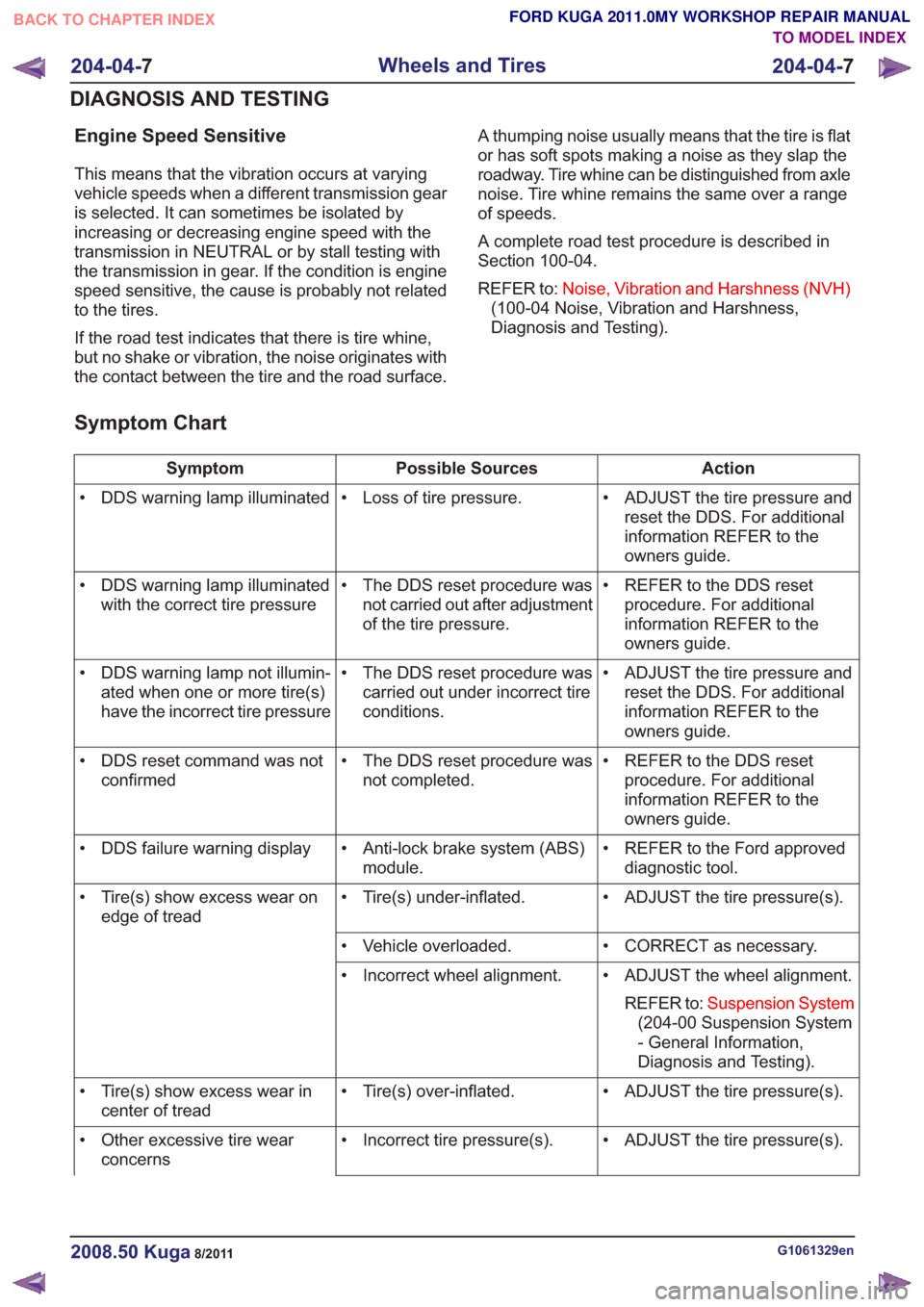
Symptom Chart
Action
Possible Sources
Symptom
• ADJUST the tire pressure andreset the DDS. For additional
information REFER to the
owners guide.
• Loss of tire pressure.
• DDS warning lamp illuminated
• REFER to the DDS resetprocedure. For additional
information REFER to the
owners guide.
• The DDS reset procedure was
not carried out after adjustment
of the tire pressure.
• DDS warning lamp illuminated
with the correct tire pressure
• ADJUST the tire pressure andreset the DDS. For additional
information REFER to the
owners guide.
• The DDS reset procedure was
carried out under incorrect tire
conditions.
• DDS warning lamp not illumin-
ated when one or more tire(s)
have the incorrect tire pressure
• REFER to the DDS resetprocedure. For additional
information REFER to the
owners guide.
• The DDS reset procedure was
not completed.
• DDS reset command was not
confirmed
• REFER to the Ford approveddiagnostic tool.
• Anti-lock brake system (ABS)
module.
• DDS failure warning display
• ADJUST the tire pressure(s).
• Tire(s) under-inflated.
• Tire(s) show excess wear on
edge of tread
• CORRECT as necessary.
• Vehicle overloaded.
• ADJUST the wheel alignment.REFER to: Suspension System
(204-00 Suspension System
- General Information,
Diagnosis and Testing).
• Incorrect wheel alignment.
• ADJUST the tire pressure(s).
• Tire(s) over-inflated.
• Tire(s) show excess wear in
center of tread
• ADJUST the tire pressure(s).
• Incorrect tire pressure(s).
• Other excessive tire wear
concerns
G1061329en2008.50 Kuga8/2011
204-04- 7
Wheels and Tires
204-04- 7
DIAGNOSIS AND TESTING
TO MODEL INDEX
BACK TO CHAPTER INDEX
FORD KUGA 2011.0MY WORKSHOP REPAIR MANUAL
Page 1235 of 2057
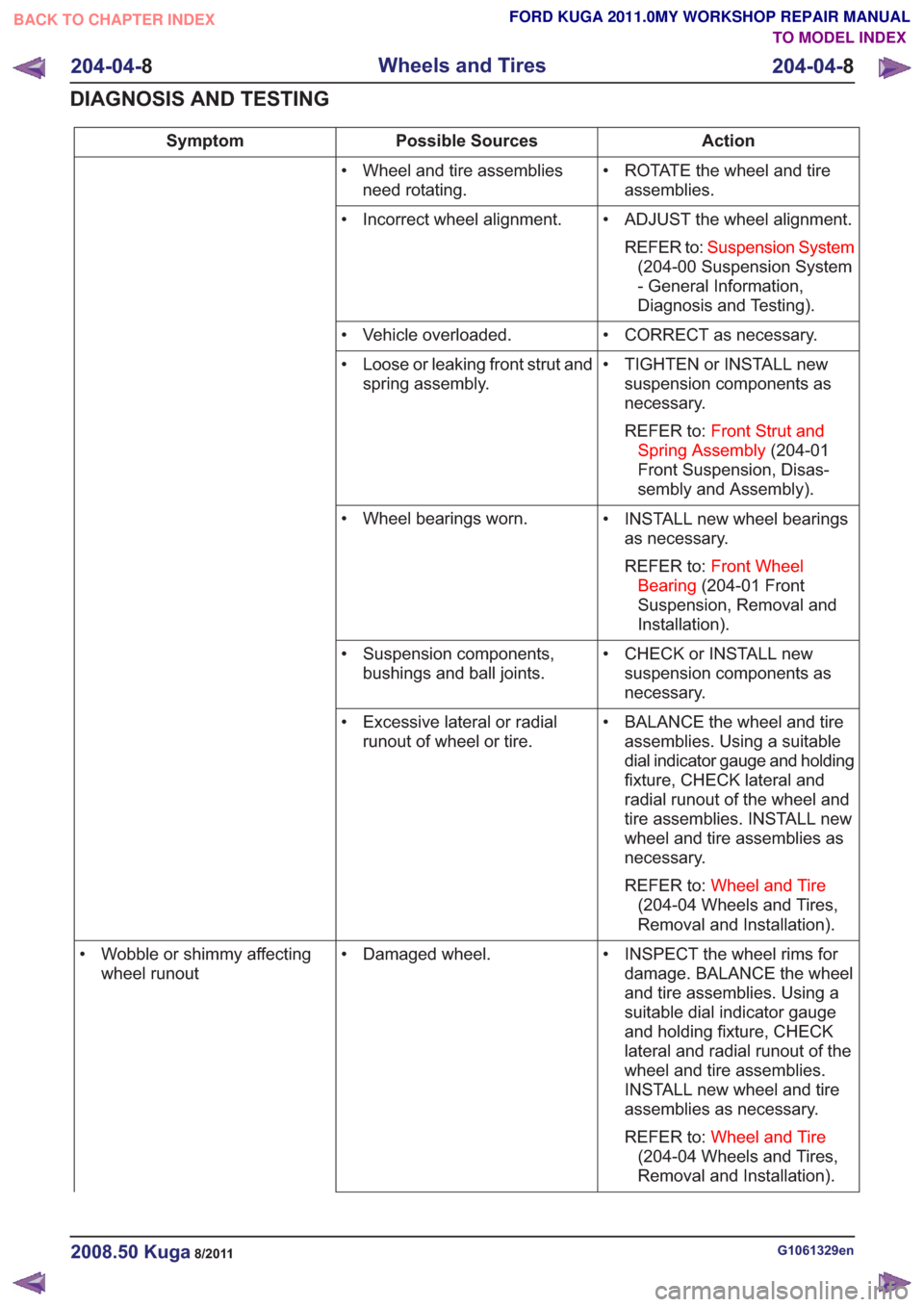
Action
Possible Sources
Symptom
• ROTATE the wheel and tireassemblies.
• Wheel and tire assemblies
need rotating.
• ADJUST the wheel alignment.REFER to: Suspension System
(204-00 Suspension System
- General Information,
Diagnosis and Testing).
• Incorrect wheel alignment.
• CORRECT as necessary.
• Vehicle overloaded.
• TIGHTEN or INSTALL newsuspension components as
necessary.
REFER to: Front Strut and
Spring Assembly (204-01
Front Suspension, Disas-
sembly and Assembly).
• Loose or leaking front strut and
spring assembly.
• INSTALL new wheel bearingsas necessary.
REFER to: Front Wheel
Bearing (204-01 Front
Suspension, Removal and
Installation).
• Wheel bearings worn.
• CHECK or INSTALL newsuspension components as
necessary.
• Suspension components,
bushings and ball joints.
• BALANCE the wheel and tireassemblies. Using a suitable
dial indicator gauge and holding
fixture, CHECK lateral and
radial runout of the wheel and
tire assemblies. INSTALL new
wheel and tire assemblies as
necessary.
REFER to: Wheel and Tire
(204-04 Wheels and Tires,
Removal and Installation).
• Excessive lateral or radial
runout of wheel or tire.
• INSPECT the wheel rims fordamage. BALANCE the wheel
and tire assemblies. Using a
suitable dial indicator gauge
and holding fixture, CHECK
lateral and radial runout of the
wheel and tire assemblies.
INSTALL new wheel and tire
assemblies as necessary.
REFER to: Wheel and Tire
(204-04 Wheels and Tires,
Removal and Installation).
• Damaged wheel.
• Wobble or shimmy affecting
wheel runout
G1061329en2008.50 Kuga8/2011
204-04- 8
Wheels and Tires
204-04- 8
DIAGNOSIS AND TESTING
TO MODEL INDEX
BACK TO CHAPTER INDEX
FORD KUGA 2011.0MY WORKSHOP REPAIR MANUAL
Page 1341 of 2057
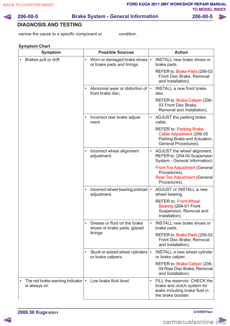
narrow the cause to a specific component or condition.
Symptom Chart
Action
Possible Sources
Symptom
• INSTALL new brake shoes orbrake pads.
REFER to: Brake Pads (206-03
Front Disc Brake, Removal
and Installation).
• Worn or damaged brake shoes
or brake pads and linings.
• Brakes pull or drift
• INSTALL a new front brakedisc.
REFER to: Brake Caliper (206-
03 Front Disc Brake,
Removal and Installation).
• Abnormal wear or distortion of
front brake disc.
• ADJUST the parking brakecable.
REFER to: Parking Brake
Cable Adjustment (206-05
Parking Brake and Actuation,
General Procedures).
• Incorrect rear brake adjust-
ment.
• ADJUST the wheel alignment.REFER to: (204-00 Suspension
System - General Information)
Front Toe Adjustment (General
Procedures),
Rear Toe Adjustment (General
Procedures).
• Incorrect wheel alignment
adjustment.
• ADJUST or INSTALL a newwheel bearing.
REFER to: Front Wheel
Bearing (204-01 Front
Suspension, Removal and
Installation).
• Incorrect wheel bearing preload
adjustment.
• INSTALL new brake shoes orbrake pads.
REFER to: Brake Pads (206-03
Front Disc Brake, Removal
and Installation).
• Grease or fluid on the brake
shoes or brake pads; glazed
linings.
• INSTALL a new wheel cylinderor brake caliper.
REFER to: Brake Caliper (206-
04 Rear Disc Brake, Removal
and Installation).
• Stuck or seized wheel cylinders
or brake calipers.
• FILL the reservoir. CHECK thebrake and clutch system for
leaks including brake fluid in
the brake booster.
• Low brake fluid level.
• The red brake warning indicator
is always on
G1058975en2008.50 Kuga8/2011
206-00- 5
Brake System - General Information
206-00- 5
DIAGNOSIS AND TESTING
TO MODEL INDEX
BACK TO CHAPTER INDEX
FORD KUGA 2011.0MY WORKSHOP REPAIR MANUAL
Page 1443 of 2057
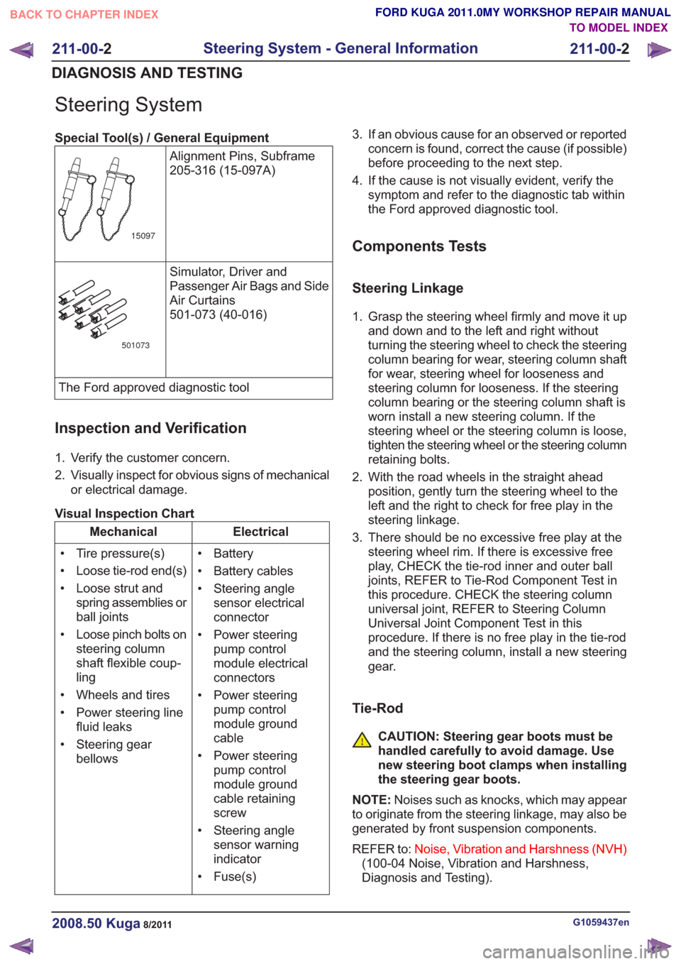
Steering System
Special Tool(s) / General EquipmentAlignment Pins, Subframe
205-316 (15-097A)
15097
Simulator, Driver and
Passenger Air Bags and Side
Air Curtains
501-073 (40-016)
501073
The Ford approved diagnostic tool
Inspection and Verification
1. Verify the customer concern.
2. Visually inspect for obvious signs of mechanicalor electrical damage.
Visual Inspection Chart
Electrical
Mechanical
• Battery
• Battery cables
• Steering anglesensor electrical
connector
• Power steering pump control
module electrical
connectors
• Power steering pump control
module ground
cable
• Power steering pump control
module ground
cable retaining
screw
• Steering angle sensor warning
indicator
• Fuse(s)
• Tire pressure(s)
• Loose tie-rod end(s)
• Loose strut and
spring assemblies or
ball joints
• Loose pinch bolts on steering column
shaft flexible coup-
ling
• Wheels and tires
• Power steering line fluid leaks
• Steering gear bellows 3. If an obvious cause for an observed or reported
concern is found, correct the cause (if possible)
before proceeding to the next step.
4. If the cause is not visually evident, verify the symptom and refer to the diagnostic tab within
the Ford approved diagnostic tool.
Components Tests
Steering Linkage
1. Grasp the steering wheel firmly and move it upand down and to the left and right without
turning the steering wheel to check the steering
column bearing for wear, steering column shaft
for wear, steering wheel for looseness and
steering column for looseness. If the steering
column bearing or the steering column shaft is
worn install a new steering column. If the
steering wheel or the steering column is loose,
tighten the steering wheel or the steering column
retaining bolts.
2. With the road wheels in the straight ahead position, gently turn the steering wheel to the
left and the right to check for free play in the
steering linkage.
3. There should be no excessive free play at the steering wheel rim. If there is excessive free
play, CHECK the tie-rod inner and outer ball
joints, REFER to Tie-Rod Component Test in
this procedure. CHECK the steering column
universal joint, REFER to Steering Column
Universal Joint Component Test in this
procedure. If there is no free play in the tie-rod
and the steering column, install a new steering
gear.
Tie-Rod
CAUTION: Steering gear boots must be
handled carefully to avoid damage. Use
new steering boot clamps when installing
the steering gear boots.
NOTE: Noises such as knocks, which may appear
to originate from the steering linkage, may also be
generated by front suspension components.
REFER to: Noise, Vibration and Harshness (NVH)
(100-04 Noise, Vibration and Harshness,
Diagnosis and Testing).
G1059437en2008.50 Kuga8/2011
211-00- 2
Steering System - General Information
211-00- 2
DIAGNOSIS AND TESTING
TO MODEL INDEX
BACK TO CHAPTER INDEX
FORD KUGA 2011.0MY WORKSHOP REPAIR MANUAL
Page 1482 of 2057
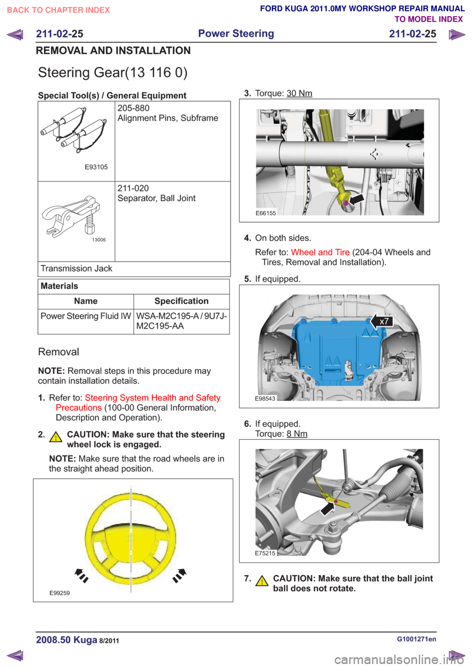
Steering Gear(13 116 0)
Special Tool(s) / General Equipment205-880
Alignment Pins, Subframe
E93105
211-020
Separator, Ball Joint
13006
Transmission Jack
Materials
Specification
Name
WSA-M2C195-A / 9U7J-
M2C195-AA
Power Steering Fluid IW
Removal
NOTE:
Removal steps in this procedure may
contain installation details.
1. Refer to: Steering System Health and Safety
Precautions (100-00 General Information,
Description and Operation).
2. CAUTION: Make sure that the steering wheel lock is engaged.
NOTE: Make sure that the road wheels are in
the straight ahead position.
E99259
3. Torque: 30Nm
E66155
4.On both sides.
Refer to: Wheel and Tire (204-04 Wheels and
Tires, Removal and Installation).
5. If equipped.
E98543
x7
6.If equipped.
Torque: 8
Nm
E75215
7. CAUTION: Make sure that the ball joint
ball does not rotate.
G1001271en2008.50 Kuga8/2011
211-02- 25
Power Steering
211-02- 25
REMOVAL AND INSTALLATION
TO MODEL INDEX
BACK TO CHAPTER INDEX
FORD KUGA 2011.0MY WORKSHOP REPAIR MANUAL