2011 FORD KUGA heating
[x] Cancel search: heatingPage 167 of 2057

reprogrammed. However, if the engine hasn't been
run since the last programmed start, the fuel-fired
booster heater will not start up the second time so
as to prevent the battery from being discharged.
The length of time required to pre-heat the vehicle
is calculated in the control unit of the fuel-fired
booster heater and is based on two temperature
values:
• Ambient air temperature: this message is taken
from the GEM via the CAN bus.
• Coolant temperature: this is determined via an internal sensor in the fuel-fired booster heater.
The maximum heating time is 30 minutes at an
outside air temperature of -10 °C or lower. The
heating time decreases proportionally with
increasing ambient temperature until the ambient
temperature is between +15 °C and +20 °C. Then
the minimum heating time is 10 minutes. The
parking heater is deactivated at temperatures
above +20 °C.
The sequence for a programmed start of the
booster heater is as follows:
• Two minutes before the start of the maximum heating time the driver information
system/instrument cluster sends an activation
message to the fuel-fired booster heater via the
CAN bus.
• The fuel-fired booster heater calculates the required heating time and, if necessary, sends
a delay request on the CAN bus.
• At the calculated time, the fuel-fired booster heater starts up. The conditions for start-up are:
engine not running and amount of fuel in the
fuel tank is above 14% of maximum.
• When the coolant temperature reaches +30 °C, the control unit of the fuel-fired booster heater
sends a request to switch on the passenger
compartment blower.
• Eight minutes after the programmed switch-off time, the booster heater stops heating mode
and starts a run-on operation to clean the
system's spark plugs.
• Ten minutes after the switch-off time, the post-cleaning operation is complete. The
additional ten minutes run-on time provides
some leeway in case the driver is late arriving.
After a programmed start-up of the booster heater
it is switched off again after the heating time has
elapsed (or if the fuel level in the fuel tank drops
below 8%). The booster heater stops within 2 minutes of the engine starting. This leaves enough
time to check whether the switch-on conditions for
boost heat mode have been met, thus preventing
the booster heater from having to switch off and
switch back on again. The heater can be switched
off manually at any time from the menu.
Whilst the fuel-fired booster heater is in additional
heating mode and/or parking heating mode, the
instrument cluster receives a fuel consumption
signal; this is used to re-calculate the vehicle's
remaining range and fuel consumption data.
Emergency shutoff
In the event of an accident in which the airbags
are deployed, the control unit of the fuel-fired
booster heater receives a message on the CAN
bus from the restraints control module (RCM).
When this message is received, the booster heater
system switches off immediately.
The booster heater control module deactivates the
system and does not respond to further messages
on the CAN bus. The booster heater control module
needs to be activated with WDS.
Component Description
Electric Booster Heater
The electric booster heater consists of three
individual heating elements, which are incorporated
into a single housing. It is controlled by the generic
electronic module (GEM), taking into account the
following factors:
Detailed illustration of fuel-fired heater
G1066982en
2008.50 Kuga 8/2011 412-02-14
Auxiliary Climate Control
412-02-14
DESCRIPTION AND OPERATIONTO MODEL INDEX
BACK TO CHAPTER INDEX
FORD KUGA 2011.0MY WORKSHOP REPAIR MANUALE97621
Page 169 of 2057
Description
Item
Combustion chamber
16
'O' Ring
17 Description
Item
Combustion blower motor cover
18
Glow plug wiring harness
19
Flame sensor
If the flame goes out independently during
operation of the booster heater, a restart is carried
out. If the booster heater does not ignite within 90
seconds of fuel delivery or if the flame goes out
within 15 minutes of starting, a lockout will be
implemented by the flame sensor.
Lockout can be cancelled by switching the booster
heater off then on again, although this may only
be repeated at most 2 times.
Overheat Sensor
The overheating sensor enables the fuel-fired
booster heater module to determine the coolant
temperature, protecting the heater from
overheating. The overheating sensor is installed
next to the coolant temperature sensor under a
cover on the top of the fuel-fired heater.
In the event of overheating (lack of water, poorly
ventilated coolant circuit), the fuel supply to the
heater is interrupted and a lockout occurs. After
the cause of the overheating has been eliminated,
the heater can be restarted by switching it off and
on again, if the coolant temperature is below 70°C.
If the heater overheats ten times in a row, the
control unit is locked.
ECT
The fuel-fired booster heater module uses the
temperature sensor to determine the coolant
temperature, which it then uses to set the starting
and stopping time. The coolant temperature sensor
is installed next to the overheating sensor under a
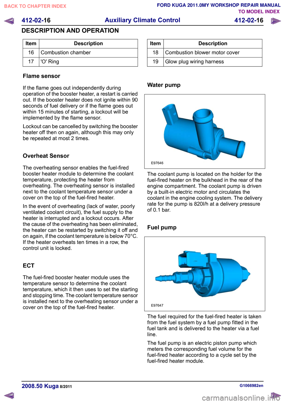
cover on the top of the fuel-fired heater. Water pump The coolant pump is located on the holder for the
fuel-fired heater on the bulkhead in the rear of the
engine compartment. The coolant pump is driven
by a built-in electric motor and circulates the
coolant in the engine cooling system. The delivery
rate for the pump is 820l/h at a delivery pressure
of 0.1 bar.
Fuel pump
The fuel required for the fuel-fired heater is taken
from the fuel system by a fuel pump fitted in the
fuel tank and is delivered to the heater via a fuel
line.
The fuel pump is an electric piston pump which
meters the corresponding fuel volume for the
fuel-fired heater according to a cycle set by the
fuel-fired heater module.
G1066982en
2008.50 Kuga 8/2011 412-02-16
Auxiliary Climate Control
412-02-16
DESCRIPTION AND OPERATIONTO MODEL INDEX
BACK TO CHAPTER INDEX
FORD KUGA 2011.0MY WORKSHOP REPAIR MANUALE97646 E97647
Page 187 of 2057

Description
Item
Instrument Cluster
1
PCM (powertrain control module)
2
EHPS (electro-hydraulic power steering)
control module
3
Audio unit
4
GEM (generic electronic module)
5
RCM (restraints control module)
6
PATS transceiver
7 Description
Item
Steering wheel lock module
8
Left-hand steering column switch
9
Fuel level sensor
10
Washer water level warning lamp switch
11
Accelerator pedal position sensor
12
CPP (clutch pedal position) sensor/BPP
(brake pedal position) sensor
13
Lighting control switch
14
System Operation
Instrument Cluster
The instrument cluster contains analog displays
as well as warning and control lamps for displaying
the system status; in addiiton, there is an LCD
indicator field for driver information.
The instrument cluster receives the following
signals from the PCM via the high speed CAN
(controller area network) Bus (HS-CAN):
• Vehicle speed – The PCM receives the necessary signalsfrom the ABS (anti-lock brake system) wheel
sensors from the ABS control unit on the
HS-CAN.
• Engine Coolant Temperature
• Engine oil pressure.
• Engine speed
The instrument cluster receives the following
signals from the GEM via the medium speed CAN
Bus (MS-CAN):
• Ambient temperature
• Brake fluid level
• Handbrake control
• Door latch control
• Liftgate latch control
• High beam control
• Headlamp flasher control
• Direction indicator control
The fuel level signal is sent by the two fuel level
sensors in the fuel pumps in the semitrailer tank,
which is wired to the instrument cluster. The
sensors are connected in series, and the total
resistance is determined from the two individual resistors. The instrument cluster converts the raw
fuel level signal into a damped fuel level value.
The odometer shows the total distance travelled
by the vehicle and is based on the same signal as
is processed for the daily mileage counter. The
value is recorded by the instrument cluster and
stored in a protected EEPROM (Electronically
Erasable Programmable Read Only Memory) area.
This area is a memory protected against
manipulation. If the instrument cluster detects an
error in this memory area, e.g. through damage,
the driver is notified with the "Odometer error"
message.
Message center
The message center is operated using the left-hand
switch on the steering column.
The SET/RESET button is activated to select a
submenu and change the settings. If signal tones
have been activated, a short acoustic signal will
sound each time a button is pressed.
By turning the rotary switch, the different menu
displays can be scrolled through or a setting
selected.
In this display, the navigation system can also
display direction and distance information.
In addition, safety and warning messages can be
displayed in this system, such as "Coolant
overheating", "Engine system error" or "Washer
fluid level too low". In addition to a safety message,
a general warning light (red/yellow) lights up.
G1030770en
2008.50 Kuga 8/2011 413-01-4
Instrument Cluster
413-01-4
DESCRIPTION AND OPERATIONTO MODEL INDEX
BACK TO CHAPTER INDEX
FORD KUGA 2011.0MY WORKSHOP REPAIR MANUAL
Page 457 of 2057

Electrical consumers are switched off when the
battery voltage is low if the GEM determines (as a
result of the message received from the PCM on
the CAN bus via the instrument cluster) that the
battery voltage has dropped below the threshold
value.
When the threshold for low battery voltage is
reached the GEM switches off the following
consumers in this order at intervals of 5 seconds:
• Heated windscreen
• Heated rear window
• Electric booster Heater
• A/C system
If the battery voltage increases back above the
lower threshold then all of the consumers which
were previously switched off are reactivated by the
GEM.
Once the electric consumers have been reactivated
their status is "switched off", i.e. the consumers
are switched off and await an input signal provided
from the relevant switch via the GEM; this means
that the driver needs to switch these components
back on again.
Electrical consumers are switched on when the
battery voltage is excessively high if the GEM
determines that the battery voltage has increased
above the threshold for overvoltage and the
charging system warning indicator has come on.
When the threshold is reached the GEM switches
on the following consumers in this order at intervals
of 5 seconds:
• Heated windscreen
• Heated rear window
When these components are deactivated again
their status is "switched off". This means that the
consumers are waiting for an input signal provided
from the relevant switch via the GEM.
Ignition overload protection
The ignition overload protection intermittently
disconnects certain circuits in order to restrict the
current being drawn from the battery while the
starter motor is operating.
The position of the ignition switch is broadcast by
the instrument cluster on the medium speed CAN
bus.
The ignition overload protection relay which is
integrated in the battery junction box is activated
by the GEM if the message "ignition switch in
position III" is received from the instrument cluster.
All of the electric consumers controlled by the
ignition overload protection relay are then switched
off.
The following consumers (among others) are
controlled by the ignition overload protection relay:
• Fog lamps
• Windscreen/rear window wash/wipe systems
• Backup lamps
• Heated washer nozzles
• Heating blower motor
• Seat heating
Headlamp switch-off delay
The headlamp switch-off delay utilizes the low
beam together with the peripheral lights (if
equipped) to illuminate the area surrounding the
vehicle. The function is activated by operating the
high beam lever when the ignition switch is in the
"0" position.
After the last door has been closed, the function
remains active for a further 30 seconds and then
switches off automatically.
When a door or the tailgate is open, the switch-off
time is extended to 180 seconds. After the last door
has been closed, the switch-off time is reset to 30
seconds.
The headlamp switch-off delay can be deactivated
prematurely by operating the high beam lever again
or by switching on the ignition.
The switch-off time is adjusted to set values at the
factory and cannot be re-programmed using the
Ford diagnostic unit.
G1030788en
2008.50 Kuga 8/2011 419-10-7
Multifunction Electronic Modules
419-10-7
DESCRIPTION AND OPERATIONTO MODEL INDEX
BACK TO CHAPTER INDEX
FORD KUGA 2011.0MY WORKSHOP REPAIR MANUAL
Page 1467 of 2057
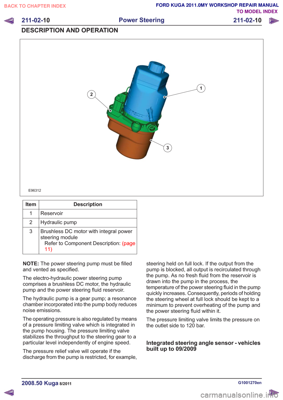
E96312
1
2
3
Description
Item
Reservoir
1
Hydraulic pump
2
Brushless DC motor with integral power
steering moduleRefertoComponentDescription:(page
11)
3
NOTE: The power steering pump must be filled
and vented as specified.
The electro-hydraulic power steering pump
comprises a brushless DC motor, the hydraulic
pump and the power steering fluid reservoir.
The hydraulic pump is a gear pump; a resonance
chamber incorporated into the pump body reduces
noise emissions.
The operating pressure is also regulated by means
of a pressure limiting valve which is integrated in
the pump housing. The pressure limiting valve
stabilizes the throughput to the steering gear to a
particular level independently of engine speed.
The pressure relief valve will operate if the
discharge from the pump is restricted, for example, steering held on full lock. If the output from the
pump is blocked, all output is recirculated through
the pump. As no fresh fluid from the reservoir is
drawn into the pump in the process, the
temperature of the power steering fluid in the pump
quickly increases. Consequently, periods of holding
the steering wheel at full lock should be kept to a
minimum to prevent overheating of the pump and
the power steering fluid within it.
The pressure limiting valve limits the pressure on
the outlet side to 120 bar.
Integrated steering angle sensor - vehicles
built up to 09/2009
G1001270en2008.50 Kuga8/2011
211-02-
10
Power Steering
211-02- 10
DESCRIPTION AND OPERATION
TO MODEL INDEX
BACK TO CHAPTER INDEX
FORD KUGA 2011.0MY WORKSHOP REPAIR MANUAL
Page 1673 of 2057
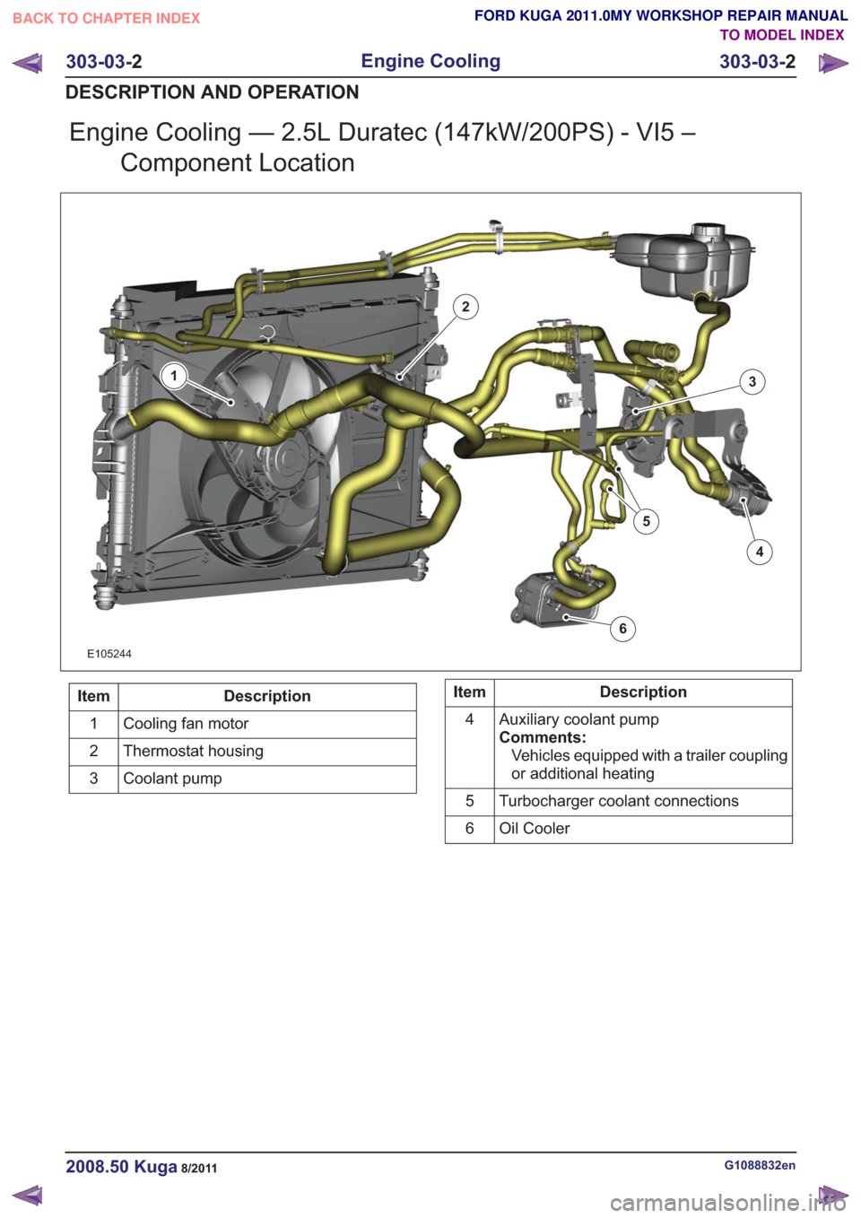
Engine Cooling — 2.5L Duratec (147kW/200PS) - VI5 –Component Location
E105244
1
2
3
4
5
6
Description
Item
Cooling fan motor
1
Thermostat housing
2
Coolant pump
3Description
Item
Auxiliary coolant pump
Comments:Vehicles equipped with a trailer coupling
or additional heating
4
Turbocharger coolant connections
5
Oil Cooler
6
G1088832en2008.50 Kuga8/2011
303-03- 2
Engine Cooling
303-03- 2
DESCRIPTION AND OPERATION
TO MODEL INDEX
BACK TO CHAPTER INDEX
FORD KUGA 2011.0MY WORKSHOP REPAIR MANUAL
Page 1674 of 2057
Engine Cooling — 2.5L Duratec (147kW/200PS) - VI5 – Overview
Auxiliary coolant pump
An electrically operated auxiliary coolant pump is
installed on vehicles with a trailer coupling and/or
additional heating. The auxiliary coolant pump
ensures that the coolant is circulated when the
coolant pump (which is driven by the engine) is not
running.
The additional heating uses the auxiliary coolant
pump to circulate hot coolant through the heat
exchanger and the engine.
On vehicles with a trailer coupling the auxiliary
coolant pump is switched on for 6 minutes by the
PCM (powertrain control module) if the coolant
temperature exceeds 106°C when the engine is
switched off. This prevents the coolant circuit from
overheating. This could happen particularly if the
engine is switched off after towing a heavy trailer
up a steep hill before there has been sufficient time
for cooling.
G1088220en2008.50 Kuga8/2011
303-03-3
Engine Cooling
303-03- 3
DESCRIPTION AND OPERATION
TO MODEL INDEX
BACK TO CHAPTER INDEX
FORD KUGA 2011.0MY WORKSHOP REPAIR MANUAL
Page 1790 of 2057
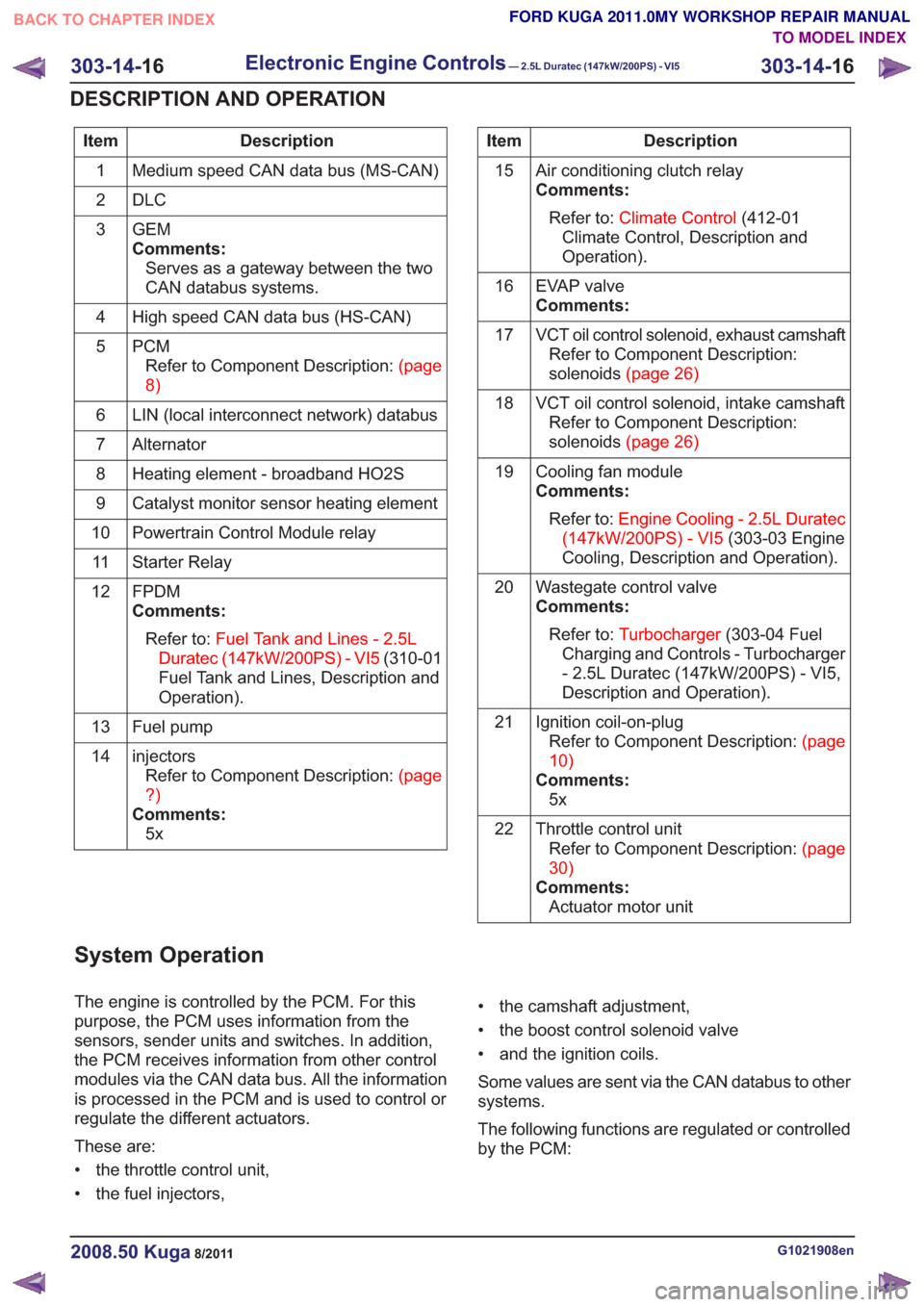
Description
Item
Medium speed CAN data bus (MS-CAN)
1
DLC
2
GEM
Comments:Serves as a gateway between the two
CAN databus systems.
3
High speed CAN data bus (HS-CAN)
4
PCMRefertoComponentDescription:(page
8)
5
LIN (local interconnect network) databus
6
Alternator
7
Heating element - broadband HO2S
8
Catalyst monitor sensor heating element
9
Powertrain Control Module relay
10
Starter Relay
11
FPDM
Comments:Refer to: Fuel Tank and Lines - 2.5L
Duratec (147kW/200PS) - VI5 (310-01
Fuel Tank and Lines, Description and
Operation).
12
Fuel pump
13
injectorsRefertoComponentDescription:(page
?)
Comments: 5x
14Description
Item
Air conditioning clutch relay
Comments:Refer to: Climate Control (412-01
Climate Control, Description and
Operation).
15
EVAP valve
Comments:
16
VCT oil control solenoid, exhaust camshaftRefer to Component Description:
solenoids(page26)
17
VCT oil control solenoid, intake camshaftRefer to Component Description:
solenoids(page26)
18
Cooling fan module
Comments:Refer to: Engine Cooling - 2.5L Duratec
(147kW/200PS) - VI5 (303-03 Engine
Cooling, Description and Operation).
19
Wastegate control valve
Comments:Refer to: Turbocharger (303-04 Fuel
Charging and Controls - Turbocharger
- 2.5L Duratec (147kW/200PS) - VI5,
Description and Operation).
20
Ignition coil-on-plugRefertoComponentDescription:(page
10)
Comments: 5x
21
Throttle control unitRefertoComponentDescription:(page
30)
Comments: Actuator motor unit
22
System Operation
The engine is controlled by the PCM. For this
purpose, the PCM uses information from the
sensors, sender units and switches. In addition,
the PCM receives information from other control
modules via the CAN data bus. All the information
is processed in the PCM and is used to control or
regulate the different actuators.
These are:
• the throttle control unit,
• the fuel injectors, • the camshaft adjustment,
• the boost control solenoid valve
• and the ignition coils.
Some values are sent via the CAN databus to other
systems.
The following functions are regulated or controlled
by the PCM:
G1021908en2008.50 Kuga8/2011
303-14-
16
Electronic Engine Controls— 2.5L Duratec (147kW/200PS) - VI5303-14-
16
DESCRIPTION AND OPERATION
TO MODEL INDEX
BACK TO CHAPTER INDEX
FORD KUGA 2011.0MY WORKSHOP REPAIR MANUAL