Page 1529 of 2057

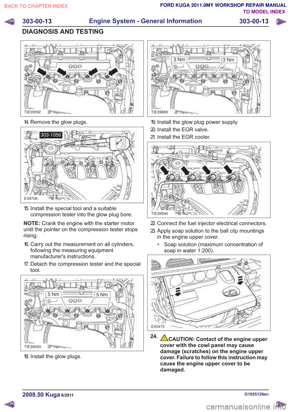
18. Install the glow plugs.
CAUTION: Contact of the engine upper
cover with the cowl panel may cause
damage (scratches) on the engine upper
cover. Failure to follow this instruction may
cause the engine upper cover to be
damaged.
G1055128en2008.50 Kuga8/2011
303-00- 13
Engine System - General Information
303-00- 13
DIAGNOSIS AND TESTING
FORD KUGA 2011.0MY WORKSHOP REPAIR MANUAL
TO MODEL INDEX
BACK TO CHAPTER INDEX
TIE39592TIE39688
E39706
303-1056
TIE39593
3Nm
TIE39594
E50473
3Nm
5Nm 5Nm
14. Remove the glow plugs.
15. Install the special tool and a suitable
compression tester into the glow plug bore.
NOTE: Crank the engine with the starter motor
until the pointer on the compression tester stops
rising.
16. Carry out the measurement on all cylinders, following the measuring equipment
manufacturer's instructions.
17. Detach the compression tester and the special tool.
19. Install the glow plug power supply.
20. Install the EGR valve.
21. Install the EGR cooler.
22. Connect the fuel injector electrical connectors.
23. Apply soap solution to the ball clip mountingsin the engine upper cover.
• Soap solution (maximum concentration of soap in water 1:200).
24.
Page 1756 of 2057

SECTION 303-07 Engine Ignition— 2.5L Duratec (147kW/200PS) - VI5
VEHICLE APPLICATION:2008.50 Kuga
PA G E
CONTENTS
SPECIFICATIONS
303-07-2
Specifications ........................................................................\
..............................................
303-07-2
Spark plugs ........................................................................\
.............................................
DIAGNOSIS AND TESTING 303-07-3
Engine Ignition ........................................................................\
............................................
303-07-3
Inspection and Verification ........................................................................\
..........................
303-07-3
Symptom Chart ........................................................................\
...........................................
REMOVAL AND INSTALLATION 303-07-4
(22 414 0)
Ignition Coil-On-Plug ........................................................................\
..............
303-07-1
Engine Ignition— 2.5L Duratec (147kW/200PS) - VI5303-07-
1
.
TO MODEL INDEX
BACK TO CHAPTER INDEX
FORD KUGA 2011.0MY WORKSHOP REPAIR MANUAL
Page 1757 of 2057
Spark plugs
mm
Description
0.7
Spark plug gap
Torque Specifications
lb-in
lb-ft
Nm
Item
28
Spark plug
G1268535en2008.50 Kuga8/2011
303-07- 2
Engine Ignition— 2.5L Duratec (147kW/200PS) - VI5303-07-
2
SPECIFICATIONS
TO MODEL INDEX
BACK TO CHAPTER INDEX
FORD KUGA 2011.0MY WORKSHOP REPAIR MANUAL
Page 1807 of 2057

Description
Item
Coil-on-plug ignition coil
1
Spark plug connector
2
Low-voltage connection
3
Laminated soft-iron core
4Description
Item
Primary winding
5
Secondary winding
6
Spark plug
7
High-voltage connection via spring contact
8
In an ignition system with coil-on-plug ignition coils,
each cylinder is actuated individually and only once
per cycle (working stroke). The coil-on-plug ignition
coils are mounted directly on the spark plugs,
therefore no ignition cables are required between
the ignition coils and the spark plugs.
Each individual ignition coil is actuated on the
low-voltage side by the PCM. The power
end-stages are incorporated into the coil-on-plug
ignition coils. Only the actuating current for these
power end-stages is controlled by the PCM.
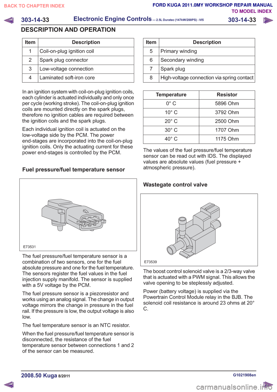
Fuel pressure/fuel temperature sensor
E73531
The fuel pressure/fuel temperature sensor is a
combination of two sensors, one for the fuel
absolute pressure and one for the fuel temperature.
The sensors register the fuel values in the fuel
injection supply manifold. The sensor is supplied
with a 5V voltage by the PCM.
The fuel pressure sensor is a piezoresistor and
works using an analog signal. The change in output
voltage mirrors the change in pressure in the fuel
rail. If the pressure is low, the output voltage is also
low.
The fuel temperature sensor is an NTC resistor.
When the fuel pressure/fuel temperature sensor is
disconnected, the resistance of the fuel
temperature sensor between connections 1 and 2
of the sensor can be measured.
Resistor
Temperature
5896 Ohm
0° C
3792 Ohm
10° C
2500 Ohm
20° C
1707 Ohm
30° C
1175 Ohm
40° C
The values of the fuel pressure/fuel temperature
sensor can be read out with IDS. The displayed
values are absolute values (fuel pressure +
atmospheric pressure).
Wastegate control valve
E73539
The boost control solenoid valve is a 2/3-way valve
that is actuated with a PWM signal. This allows the
valve opening to be steplessly adjusted.
Power (battery voltage) is supplied via the
Powertrain Control Module relay in the BJB. The
solenoid coil resistance is around 23 ohms at 20°
C.
G1021908en2008.50 Kuga8/2011
303-14- 33
Electronic Engine Controls— 2.5L Duratec (147kW/200PS) - VI5303-14-
33
DESCRIPTION AND OPERATION
TO MODEL INDEX
BACK TO CHAPTER INDEX
FORD KUGA 2011.0MY WORKSHOP REPAIR MANUAL
Page 1836 of 2057

• Selector lever position and selector leverposition display
• Fluid leakage
• Transmission fluid level check
• Transmission fluid quality check
• Modification/retrofitting
• Mechanical damage to the transmission
When inspecting connectors, remember that the
plugs may only be disconnected when they are not
energized.
The transaxle electronics may be destroyed by
static charge. To prevent damage, it must be
ensured that the technician complies with the
corresponding safeguards.
NOTE: Refer to the service literature for an exact
description of these safeguards.
Towing the vehicle
E66463
In general, vehicles with the AW55 transaxle can
be towed. Vehicles must never be towed
backwards.
As a result of the reduced lubrication of the
transaxle during towing, the following must be
remembered:
• The selector lever must be in the 'N' position.
• The maximum towing speed must not exceed 50 km/h.
• The maximum towing distance must not exceed 50 kilometers.
Push-starting the Vehicle
No torque is transmitted when towing or pushing
the vehicle. For this reason, vehicles with an
automatic transaxle cannot and must not be
tow-started or push-started.
Jump-starting the Vehicle
CAUTION: When jump-starting the vehicle
using a jumper lead there may be voltage
peaks. These may destroy the transaxle
electronics.
NOTE: When jump-starting the vehicle, the external
battery must remain connected for several minutes.
The voltage peaks dissipate after a few minutes.
Only then may the external battery be disconnected
without the risk of damage.
Selector Lever Emergency Release
E114512
1
2
3
4
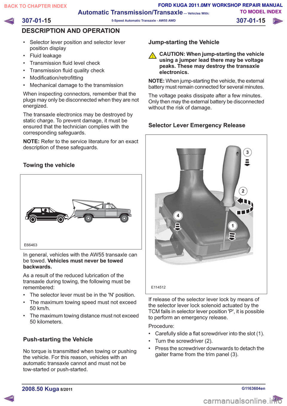
If release of the selector lever lock by means of
the selector lever lock solenoid actuated by the
TCM fails in selector lever position 'P', it is possible
to perform an emergency release.
Procedure:
• Carefully slide a flat screwdriver into the slot (1).
• Turn the screwdriver (2).
• Press the screwdriver downwards to detach the gaiter frame from the trim panel (3).
G1163604en2008.50 Kuga8/2011
307-01- 15
Automatic Transmission/Transaxle
— Vehicles With:
5-Speed Automatic Transaxle - AW55 AWD
307-01- 15
DESCRIPTION AND OPERATION
TO MODEL INDEX
BACK TO CHAPTER INDEX
FORD KUGA 2011.0MY WORKSHOP REPAIR MANUAL