2011 FORD KUGA Camshaft install
[x] Cancel search: Camshaft installPage 1627 of 2057
Engine(21 134 8)
Assembly
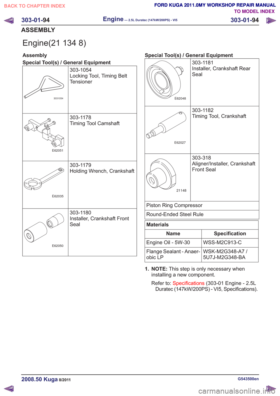
Special Tool(s) / General Equipment303-1054
Locking Tool, Timing Belt
Tensioner
3031054
303-1178
Timing Tool Camshaft
E62051
303-1179
Holding Wrench, Crankshaft
E62035
303-1180
Installer, Crankshaft Front
Seal
E62050
Special Tool(s) / General Equipment303-1181
Installer, Crankshaft Rear
Seal
E62048
303-1182
Timing Tool, Crankshaft
E62027
303-318
Aligner/Installer, Crankshaft
Front Seal
21148
Piston Ring Compressor
Round-Ended Steel Rule
Materials
Specification
Name
WSS-M2C913-C
Engine Oil - 5W-30
WSK-M2G348-A7 /
5U7J-M2G348-BA
Flange Sealant - Anaer-
obic LP
1. NOTE: This step is only necessary when
installing a new component.
Refer to: Specifications (303-01 Engine - 2.5L
Duratec (147kW/200PS) - VI5, Specifications).
G543500en2008.50 Kuga8/2011
303-01- 94
Engine— 2.5L Duratec (147kW/200PS) - VI5303-01-
94
ASSEMBLY
TO MODEL INDEX
BACK TO CHAPTER INDEX
FORD KUGA 2011.0MY WORKSHOP REPAIR MANUAL FORD KUGA 2011.0MY WORKSHOP REPAIR MANUAL
FORD KUGA 2011.0MY WORKSHOP REPAIR MANUAL
FORD KUGA 2011.0MY WORKSHOP REPAIR MANUAL
FORD KUGA 2011.0MY WORKSHOP REPAIR MANUAL
FORD KUGA 2011.0MY WORKSHOP REPAIR MANUAL
Page 1696 of 2057
Action
Possible Sources
Symptom
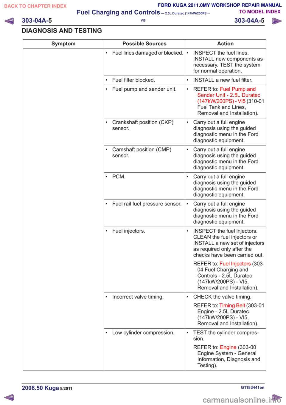
• INSPECT the fuel lines.INSTALL new components as
necessary. TEST the system
for normal operation.
• Fuel lines damaged or blocked.
• INSTALL a new fuel filter.
• Fuel filter blocked.
• REFER to:Fuel Pump and
Sender Unit - 2.5L Duratec
(147kW/200PS) - VI5 (310-01
Fuel Tank and Lines,
Removal and Installation).
• Fuel pump and sender unit.
• Carry out a full enginediagnosis using the guided
diagnostic menu in the Ford
diagnostic equipment.
• Crankshaft position (CKP)
sensor.
• Carry out a full enginediagnosis using the guided
diagnostic menu in the Ford
diagnostic equipment.
• Camshaft position (CMP)
sensor.
• Carry out a full enginediagnosis using the guided
diagnostic menu in the Ford
diagnostic equipment.
•PCM.
• Carry out a full enginediagnosis using the guided
diagnostic menu in the Ford
diagnostic equipment.
• Fuel rail fuel pressure sensor.
• INSPECT the fuel injectors.CLEAN the fuel injectors or
INSTALL a new set of injectors
as required only after the
checks have been carried out.
REFER to: Fuel Injectors (303-
04 Fuel Charging and
Controls - 2.5L Duratec
(147kW/200PS) - VI5,
Removal and Installation).
• Fuel injectors.
• CHECK the valve timing.REFER to: Timing Belt (303-01
Engine - 2.5L Duratec
(147kW/200PS) - VI5,
Removal and Installation).
• Incorrect valve timing.
• TEST the cylinder compres-sion.
REFER to: Engine(303-00
Engine System - General
Information, Diagnosis and
Testing).
• Low cylinder compression.
G1183441en2008.50 Kuga8/2011
303-04A-
5
Fuel Charging and Controls
— 2.5L Duratec (147kW/200PS) -
VI5
303-04A- 5
DIAGNOSIS AND TESTING
TO MODEL INDEX
BACK TO CHAPTER INDEX
FORD KUGA 2011.0MY WORKSHOP REPAIR MANUAL
Page 1708 of 2057
Action
Possible Sources
Symptom
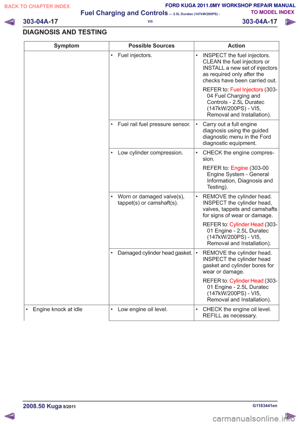
• INSPECT the fuel injectors.CLEAN the fuel injectors or
INSTALL a new set of injectors
as required only after the
checks have been carried out.
REFER to: Fuel Injectors (303-
04 Fuel Charging and
Controls - 2.5L Duratec
(147kW/200PS) - VI5,
Removal and Installation).
• Fuel injectors.
• Carry out a full enginediagnosis using the guided
diagnostic menu in the Ford
diagnostic equipment.
• Fuel rail fuel pressure sensor.
• CHECK the engine compres-sion.
REFER to: Engine(303-00
Engine System - General
Information, Diagnosis and
Testing).
• Low cylinder compression.
• REMOVE the cylinder head.INSPECT the cylinder head,
valves, tappets and camshafts
for signs of wear or damage.
REFER to: Cylinder Head (303-
01 Engine - 2.5L Duratec
(147kW/200PS) - VI5,
Removal and Installation).
• Worn or damaged valve(s),
tappet(s) or camshaft(s).
• REMOVE the cylinder head.INSPECT the cylinder head
gasket and cylinder bores for
wear or damage.
REFER to: Cylinder Head (303-
01 Engine - 2.5L Duratec
(147kW/200PS) - VI5,
Removal and Installation).
• Damaged cylinder head gasket.
• CHECK the engine oil level.REFILL as necessary.
• Low engine oil level.
• Engine knock at idle
G1183441en2008.50 Kuga8/2011
303-04A- 17
Fuel Charging and Controls
— 2.5L Duratec (147kW/200PS) -
VI5
303-04A- 17
DIAGNOSIS AND TESTING
TO MODEL INDEX
BACK TO CHAPTER INDEX
FORD KUGA 2011.0MY WORKSHOP REPAIR MANUAL
Page 1776 of 2057
303-14-34
Exterior aor temperature sensor ........................................................................\
.............
DIAGNOSIS AND TESTING 303-14-35
Electronic Engine Controls ........................................................................\
.........................
303-14-35
Inspection and Verification ........................................................................\
..........................
REMOVAL AND INSTALLATION 303-14-36
(29 232 0)
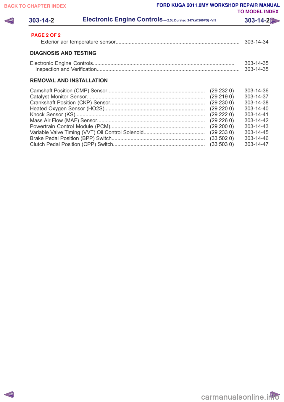
Camshaft Position (CMP) Sensor ...................................................................
303-14-37
(29 219 0)
Catalyst Monitor Sensor ........................................................................\
.........
303-14-38
(29 230 0)
Crankshaft Position (CKP) Sensor .................................................................
303-14-40
(29 220 0)
Heated Oxygen Sensor (HO2S) .....................................................................
303-14-41
(29 222 0)
Knock Sensor (KS) ........................................................................\
.................
303-14-42
(29 226 0)
Mass Air Flow (MAF) Sensor ........................................................................\
..
303-14-43
(29 200 0)
Powertrain Control Module (PCM) .................................................................
303-14-45
(29 233 0)
Variable Valve Timing (VVT) Oil Control Solenoid ..........................................
303-14-46
(33 502 0)
Brake Pedal Position (BPP) Switch ................................................................
303-14-47
(33 503 0)
Clutch Pedal Position (CPP) Switch ...............................................................
303-14-2
Electronic Engine Controls— 2.5L Duratec (147kW/200PS) - VI5303-14-
2
.
TO MODEL INDEX
BACK TO CHAPTER INDEX
PAGE 2 OF 2
FORD KUGA 2011.0MY WORKSHOP REPAIR MANUAL
Page 1782 of 2057
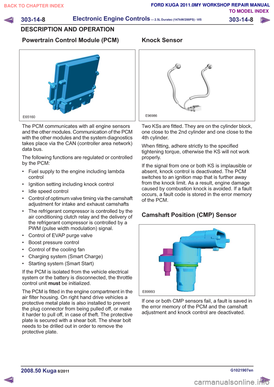
Powertrain Control Module (PCM)
E65160
The PCM communicates with all engine sensors
and the other modules. Communication of the PCM
with the other modules and the system diagnostics
takes place via the CAN (controller area network)
data bus.
The following functions are regulated or controlled
by the PCM:
• Fuel supply to the engine including lambdacontrol
• Ignition setting including knock control
• Idle speed control
• Control of optimum valve timing via the camshaft adjustment for intake and exhaust camshafts
• The refrigerant compressor is controlled by the air conditioning clutch relay and the delivery of
the refrigerant compressor is controlled by a
PWM (pulse width modulation) signal.
• Control of EVAP purge valve
• Boost pressure control
• Control of the cooling fan
• Charging system (Smart Charge)
• Starting system (Smart Start)
If the PCM is isolated from the vehicle electrical
system or the battery is disconnected, the throttle
control unit mustbe initialized.
The PCM is fitted in the engine compartment in the
air filter housing. On right hand drive vehicles a
protective metal plate is also installed to prevent
the plug connector from being pulled off, or make
it harder to pull off, in case of theft. The protective
plate is secured with a shear bolt. The shear bolt
needs to be drilled out in order to remove the
protective plate.
Knock Sensor
E96986
Two KSs are fitted. They are on the cylinder block,
one close to the 2nd cylinder and one close to the
4th cylinder.
When fitting, adhere strictly to the specified
tightening torque, otherwise the KS will not work
properly.
If the signal from one or both KS is implausible or
absent, knock control is deactivated. The PCM
switches to an ignition map that is further away
from the knock limit. As a result, engine damage
caused by combustion knock is avoided. If a fault
occurs, a fault code is stored in the error memory
of the PCM.
Camshaft Position (CMP) Sensor
E89993
If one or both CMP sensors fail, a fault is saved in
the error memory of the PCM and the camshaft
adjustment and knock control are deactivated.
G1021907en2008.50 Kuga8/2011
303-14- 8
Electronic Engine Controls— 2.5L Duratec (147kW/200PS) - VI5303-14-
8
DESCRIPTION AND OPERATION
TO MODEL INDEX
BACK TO CHAPTER INDEX
FORD KUGA 2011.0MY WORKSHOP REPAIR MANUAL
Page 1783 of 2057
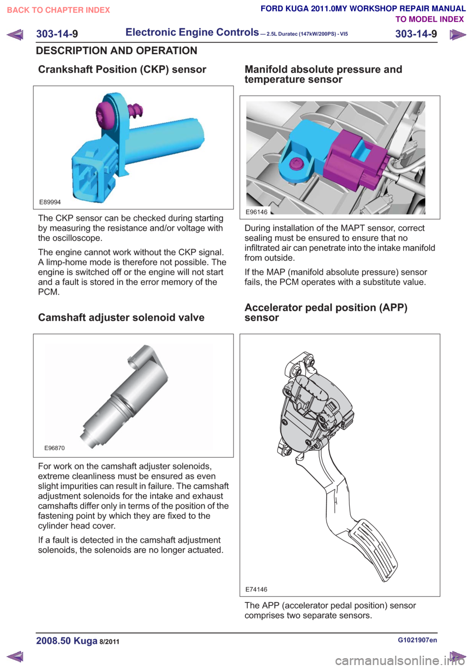
Crankshaft Position (CKP) sensor
E89994
The CKP sensor can be checked during starting
by measuring the resistance and/or voltage with
the oscilloscope.
The engine cannot work without the CKP signal.
A limp-home mode is therefore not possible. The
engine is switched off or the engine will not start
and a fault is stored in the error memory of the
PCM.
Camshaft adjuster solenoid valve
E96870
For work on the camshaft adjuster solenoids,
extreme cleanliness must be ensured as even
slight impurities can result in failure. The camshaft
adjustment solenoids for the intake and exhaust
camshafts differ only in terms of the position of the
fastening point by which they are fixed to the
cylinder head cover.
If a fault is detected in the camshaft adjustment
solenoids, the solenoids are no longer actuated.
Manifold absolute pressure and
temperature sensor
E96146
During installation of the MAPT sensor, correct
sealing must be ensured to ensure that no
infiltrated air can penetrate into the intake manifold
from outside.
If the MAP (manifold absolute pressure) sensor
fails, the PCM operates with a substitute value.
Accelerator pedal position (APP)
sensor
E74146
The APP (accelerator pedal position) sensor
comprises two separate sensors.
G1021907en2008.50 Kuga8/2011
303-14-9
Electronic Engine Controls— 2.5L Duratec (147kW/200PS) - VI5303-14-
9
DESCRIPTION AND OPERATION
TO MODEL INDEX
BACK TO CHAPTER INDEX
FORD KUGA 2011.0MY WORKSHOP REPAIR MANUAL
Page 1794 of 2057
than to a change in the throttle valve position. The
ignition timing also changes much more quickly.
To keep the ignition point as close as possible to
the knock limit and so optimize the efficiency of the
engine, two KS are installed in the engine, which
pick up the mechanical vibrations of the engine
and convert them into an electrical signal for the
PCM.
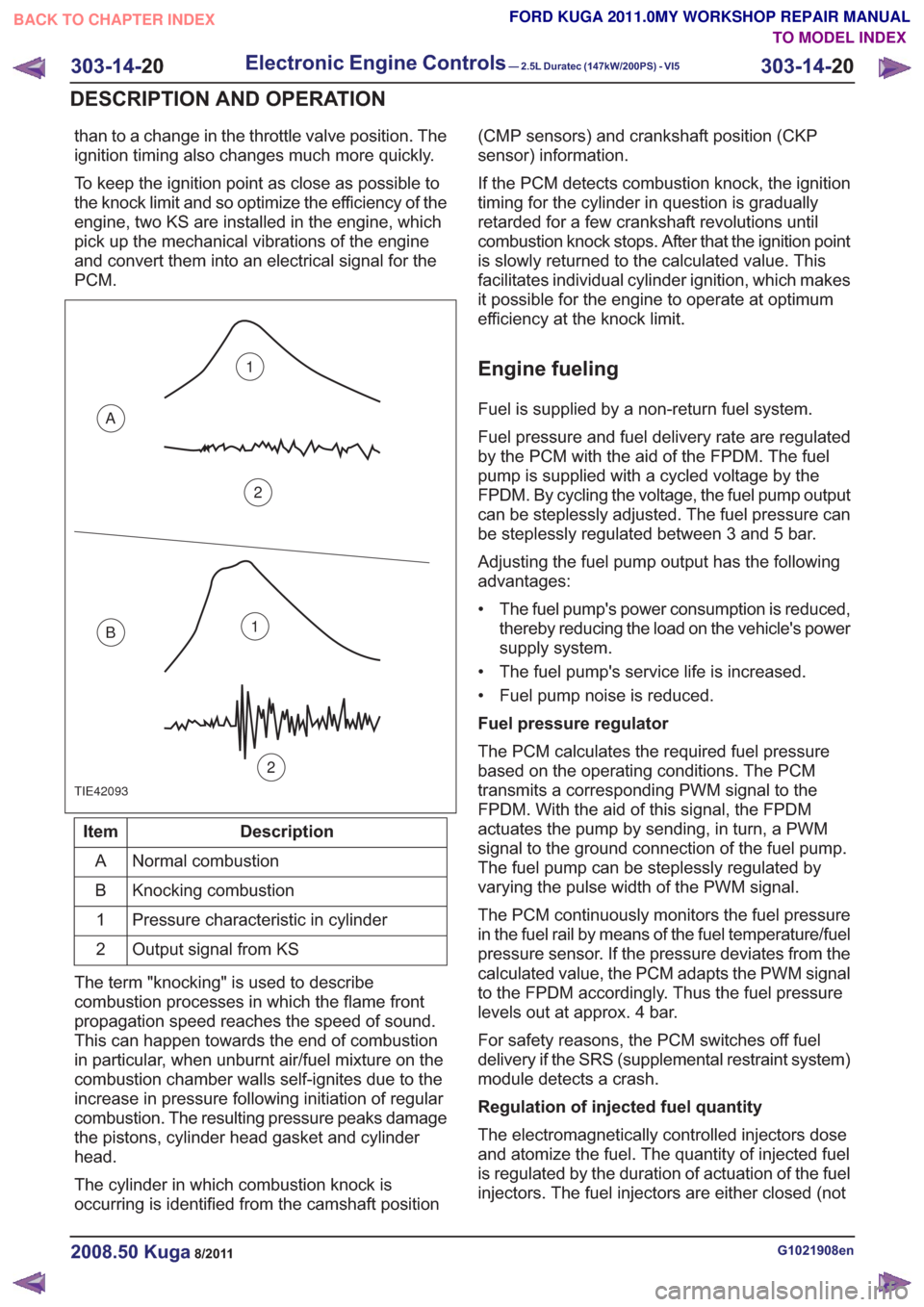
TIE42093
1
2
A
B1
2
Description
Item
Normal combustion
A
Knocking combustion
B
Pressure characteristic in cylinder
1
Output signal from KS
2
The term "knocking" is used to describe
combustion processes in which the flame front
propagation speed reaches the speed of sound.
This can happen towards the end of combustion
in particular, when unburnt air/fuel mixture on the
combustion chamber walls self-ignites due to the
increase in pressure following initiation of regular
combustion. The resulting pressure peaks damage
the pistons, cylinder head gasket and cylinder
head.
The cylinder in which combustion knock is
occurring is identified from the camshaft position (CMP sensors) and crankshaft position (CKP
sensor) information.
If the PCM detects combustion knock, the ignition
timing for the cylinder in question is gradually
retarded for a few crankshaft revolutions until
combustion knock stops. After that the ignition point
is slowly returned to the calculated value. This
facilitates individual cylinder ignition, which makes
it possible for the engine to operate at optimum
efficiency at the knock limit.
Engine fueling
Fuel is supplied by a non-return fuel system.
Fuel pressure and fuel delivery rate are regulated
by the PCM with the aid of the FPDM. The fuel
pump is supplied with a cycled voltage by the
FPDM. By cycling the voltage, the fuel pump output
can be steplessly adjusted. The fuel pressure can
be steplessly regulated between 3 and 5 bar.
Adjusting the fuel pump output has the following
advantages:
• The fuel pump's power consumption is reduced,
thereby reducing the load on the vehicle's power
supply system.
• The fuel pump's service life is increased.
• Fuel pump noise is reduced.
Fuel pressure regulator
The PCM calculates the required fuel pressure
based on the operating conditions. The PCM
transmits a corresponding PWM signal to the
FPDM. With the aid of this signal, the FPDM
actuates the pump by sending, in turn, a PWM
signal to the ground connection of the fuel pump.
The fuel pump can be steplessly regulated by
varying the pulse width of the PWM signal.
The PCM continuously monitors the fuel pressure
in the fuel rail by means of the fuel temperature/fuel
pressure sensor. If the pressure deviates from the
calculated value, the PCM adapts the PWM signal
to the FPDM accordingly. Thus the fuel pressure
levels out at approx. 4 bar.
For safety reasons, the PCM switches off fuel
delivery if the SRS (supplemental restraint system)
module detects a crash.
Regulation of injected fuel quantity
The electromagnetically controlled injectors dose
and atomize the fuel. The quantity of injected fuel
is regulated by the duration of actuation of the fuel
injectors. The fuel injectors are either closed (not
G1021908en2008.50 Kuga8/2011
303-14- 20
Electronic Engine Controls— 2.5L Duratec (147kW/200PS) - VI5303-14-
20
DESCRIPTION AND OPERATION
TO MODEL INDEX
BACK TO CHAPTER INDEX
FORD KUGA 2011.0MY WORKSHOP REPAIR MANUAL
Page 1797 of 2057
Calculation of valve timing adjustment
angle
The 2.5L Duratec (VI5) engine has two camshaft
adjustment units which work independently of each
other.
One camshaft adjustment solenoid is installed for
each intake camshaft and exhaust camshaft.
This allows the PCM to continuously adjust the
intake and exhaust-side camshaft adjustments
independently of one another. The timing is
adjusted by the PCM using curves; adjustment is
primarily done as a function of engine load and
engine speed.
In this way the engine performance is increased
and internal exhaust gas recirculation is realized.
The advantages of camshaft adjustment are as
follows:
• Higher torque and improved torquecharacteristics
• Reduced fuel consumption
• Improved emissions performance
The camshaft adjustment solenoids are actuated
by the PWM by means of a PCM signal.
Continuous adjustment of the camshafts by the
PCM is achieved by means of the camshaft
adjustment solenoids, the camshaft adjustment
units and two CMP sensors. A defined quantity of
engine is oil is supplied to or drained from the
adjustment units via the camshaft adjustment
solenoids. The existing EOP (engine oil pressure)
is taken into account in the process. In this way
the valve timings are adjusted according to the
operating condition of the engine. The camshaft
adjusters work according to the vane-cell principle.
On starting the engine, both camshafts are
mechanically locked in their starting positions. The
intake camshaft is in the maximum late position
and the exhaust camshaft in the maximum early
position.
Control is divided into four main areas:
• Low engine speed and low load
• Partial load
• Low engine speed and high load
• High engine speed and high load
At low engine speed and low load, the exhaust
valves open early and the intake valves open late.
The result is reduced fuel consumption and more
uniform idling. In the partial load range, the exhaust valves and
the intake valves open late. The late opening of
the exhaust valves results in a good utilization of
the expanding gases in the cylinder. Closing the
exhaust valves after Top Dead Center allows
internal exhaust gas recirculation through aspiration
of exhaust gases into the combustion chamber.
Moreover, the intake valves close after Bottom
Dead Centre, allowing the fresh air/fuel mixture
and exhaust gases to flow back into the intake
tract. The result is reduced fuel consumption and
low emissions.
At low engine speed and high engine load, the
exhaust valves open late and the intake valves
open early. Due to the resulting valve opening
overlap at Top Dead Centre, the pulsating gas
column within the combustion chamber is utilized
to achieve better charging of the combustion
chamber. The result is increased torque at lower
RPM.
At high engine speeds and high engine load, the
exhaust valves open early and the intake valves
close late. Because a rapid gas exchange must be
achieved at high engine speeds, the early opening
of the exhaust valves achieves better expulsion of
the exhaust gas and the late closing of the intake
valves improves cylinder charge efficiency.
Optimum power output is achieved.
Many other camshaft positions are possible in
addition to these settings.
In order to avoid a malfunction in the camshaft
adjustment units at excessively low ambient or
engine-oil temperatures, they are activated by the
PCM with a time delay via the camshaft adjustment
solenoids. The PCM receives the information
required for this from the ECT sensor and the
outside air temperature sensor.
When idling and during deceleration, the camshaft
adjustment solenoids are activated repeatedly by
the PCM in order to remove any dirt which may be
on the bore holes and ring grooves.
Boost pressure control
Optimum regulation is achieved by means of an
electronically-controlled solenoid valve, the boost
control solenoid valve.
Refer to:
Turbocharger (303-04 Fuel Charging and
Controls - Turbocharger - 2.5L Duratec
(147kW/200PS) - VI5, Description and
Operation).
G1021908en2008.50 Kuga8/2011
303-14- 23
Electronic Engine Controls— 2.5L Duratec (147kW/200PS) - VI5303-14-
23
DESCRIPTION AND OPERATION
TO MODEL INDEX
BACK TO CHAPTER INDEX
FORD KUGA 2011.0MY WORKSHOP REPAIR MANUAL