2011 FORD KUGA Index
[x] Cancel search: IndexPage 1821 of 2057
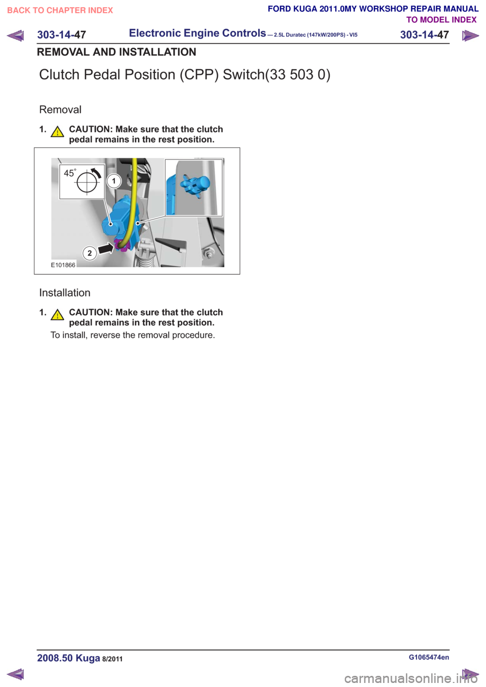
Clutch Pedal Position (CPP) Switch(33 503 0)
Removal
1. CAUTION: Make sure that the clutchpedal remains in the rest position.
2
451
E101866
Installation
1.CAUTION: Make sure that the clutch
pedal remains in the rest position.
To install, reverse the removal procedure.
G1065474en2008.50 Kuga8/2011
303-14- 47
Electronic Engine Controls— 2.5L Duratec (147kW/200PS) - VI5303-14-
47
REMOVAL AND INSTALLATION
TO MODEL INDEX
BACK TO CHAPTER INDEX
FORD KUGA 2011.0MY WORKSHOP REPAIR MANUAL
Page 1822 of 2057
SECTION 307-01 Automatic Transmission/Transaxle
— Vehicles With: 5-Speed Automatic Transaxle - AW55 AWD
VEHICLE APPLICATION:2008.50 Kuga
PA G E
CONTENTS
SPECIFICATIONS
307-01-4
Specifications ........................................................................\
..............................................
DESCRIPTION AND OPERATION 307-01-5
Transmission Description (Component Location) ...............................................................
307-01-6
Transmission Description (Overview) ........................................................................\
.........
307-01-6
Components of the AW55 automatic transaxle ..................................................................
307-01-6
General overview ........................................................................\
....................................
307-01-8
Transaxle cooling ........................................................................\
....................................
307-01-8
External shift mechanism ........................................................................\
........................
307-01-9
Components of the electronic control ........................................................................\
.....
307-01-11
Overview of the brakes, clutches and one-way clutches ................................................
307-01-12
Input and output signals at the TCM ........................................................................\
.......
307-01-14
Knowing and Understanding Customer Concerns ..........................................................
307-01-14
Testing Possible Causes of Transmission Control Faults ...............................................
307-01-14
IDS Diagnosis ........................................................................\
.........................................
307-01-14
visual inspection ........................................................................\
.....................................
307-01-15
Towing the vehicle ........................................................................\
..................................
307-01-15
Push-starting the Vehicle ........................................................................\
........................
307-01-15
Jump-starting the Vehicle ........................................................................\
.......................
307-01-15
Selector Lever Emergency Release ........................................................................\
.......
307-01-16
Adjusting the Selector Lever Cable ........................................................................\
........
307-01-17
Transmission Fluid Level Check ........................................................................\
.............
307-01-17
Changing the Transmission Fluid ........................................................................\
...........
307-01-18
Diagnosis with IDS ........................................................................\
..................................
307-01-19
Resetting the counter for fluid change intervals. .............................................................
307-01-19
Programming the 'N' position of the TR sensor..............................................................
307-01-19
Resetting the values learned by the TCM .......................................................................
307-01-21
Transmission Description (System Operation and Component Description) .....................
307-01-21
System Operation ........................................................................\
.......................................
307-01-22
Functionality overview ........................................................................\
............................
307-01-24
Electronic Control System ........................................................................\
......................
307-01-24
Hydraulic Control System ........................................................................\
.......................
307-01-24
Type plate ........................................................................\
...............................................
307-01-25
Serial number of the transmission ........................................................................\
..........
307-01-25
Markings on the TCM ........................................................................\
.............................
307-01-25
Serial
number of the TCM ........................................................................\
.......................
307-01-25
Transmission Control ........................................................................\
..............................
307-01-27
Pin assignment for TCM connector 'C' (connection to transaxle) ...................................
307-01-28
Operation ........................................................................\
................................................
307-01-29
Gearshift control ........................................................................\
......................................
307-01-29
Adaptation ........................................................................\
...............................................
307-01-29
Shifting from 'P' to another transmission range ..............................................................
307-01-1
Automatic Transmission/Transaxle
— Vehicles With:
5-Speed Automatic Transaxle - AW55 AWD
307-01- 1
.
TO MODEL INDEX
BACK TO CHAPTER INDEX
PAGE 1 OF 3 FORD KUGA 2011.0MY WORKSHOP REPAIR MANUAL
Page 1823 of 2057
307-01-29
Automatic transmission, selector lever in position "D". ...................................................
307-01-29
Sport mode, selector lever in position "S" .......................................................................
307-01-29
Changing gear in select-shift mode........................................................................\
........
307-01-30
Selector lever from 'N' to 'R' position ........................................................................\
......
307-01-30
Self-test and Diagnosis ........................................................................\
...........................
307-01-30
Temperature controlled torque converter lockup ............................................................
307-01-30
Slip locking ........................................................................\
..............................................
307-01-30
Hill climbing ........................................................................\
.............................................
307-01-31
Downhill driving ........................................................................\
.......................................
307-01-31
Hill-hold function ........................................................................\
.....................................
307-01-31
Altitude correction ........................................................................\
...................................
307-01-31
Selector lever lock ........................................................................\
..................................
307-01-31
Shifting from P into another transmission range .............................................................
307-01-31
Shifting from N into another transmission range .............................................................
307-01-31
Power flow through the transmission ........................................................................\
......
307-01-31
Clutches and brakes ........................................................................\
...............................
307-01-33
Position P (park) ........................................................................\
.....................................
307-01-34
Position N (neutral) ........................................................................\
.................................
307-01-35
Position D, 1st gear........................................................................\
................................
307-01-36
Position D, 2nd gear ........................................................................\
...............................
307-01-37
Position D, 3rd gear ........................................................................\
................................
307-01-38
Position D, 4th gear ........................................................................\
................................
307-01-39
Position D, 5th gear ........................................................................\
................................
307-01-40
Position R (reverse) ........................................................................\
................................
307-01-41
Service instructions ........................................................................\
.................................
307-01-41
Towing procedure ........................................................................\
...................................
307-01-42
Reset adaptation data ........................................................................\
.............................
307-01-42
Limp home mode ........................................................................\
....................................
307-01-42
Component Description ........................................................................\
..............................
Tasks of the electronic components ........................................................................\
........
307-01-44
Input signals ........................................................................\
............................................
307-01-45
Output signals ........................................................................\
.........................................
Control valve assembly ........................................................................\
...........................
Shift solenoids S1 - S5 ........................................................................\
...........................
PWM-
solenoid valve – TCC (SLU) ........................................................................\
........
PWM solenoid valve – shift pressure (SLS) ...................................................................
PWM solenoid valve for main line pressure (SLT) ..........................................................
307-01-52
Installation position ........................................................................\
.................................
Operation ........................................................................\
................................................
Selector lever with integrated select-shift switch module ...............................................
Oil pump ........................................................................\
..................................................
Torque converter with TCC ........................................................................\
.....................
The TSS sensor ........................................................................\
......................................
The OSS sensor ........................................................................\
.....................................
The TFT sensor ........................................................................\
......................................
The TR sensor ........................................................................\
........................................
GENERAL PROCEDURES
T ransmission Fluid Level Check ........................................................................\
.................
307-01-63
T ransmission Fluid Drain and Refill ........................................................................\
............
REMOVAL AND INSTALLATION 307-01-67
Halfshaft Seal LH ........................................................................\
........................................
307-01-68
Halfshaft Seal RH........................................................................\
.......................................
307-01-69
Main Control Valve Body ........................................................................\
............................
307-01-2
Automatic Transmission/Transaxle
— Vehicles With:
5-Speed Automatic Transaxle - AW55 AWD
307-01- 2
.
TO MODEL INDEX
BACK TO CHAPTER INDEX
307-01-42
307-01-49
307-01-52 307-01-47
307-01-45
307-01-50
307-01-51
307-01-53
307-01-55
307-01-54
307-01-56
307-01-57
307-01-58
307-01-61 307-01-60
PAGE 2 OF 3 FORD KUGA 2011.0MY WORKSHOP REPAIR MANUAL
Page 1824 of 2057
307-01-72
Output Shaft Speed (OSS) Sensor ........................................................................\
.............
307-01-73
Torque Converter Seal ........................................................................\
................................
307-01-75
Transmission Fluid Pan ........................................................................\
..............................
307-01-77
Transmission Range (TR) Sensor ........................................................................\
..............
307-01-81
Turbine Shaft Speed (TSS) Sensor ........................................................................\
............
REMOVAL 307-01-82
Transmission ........................................................................\
..............................................
INSTALLATION 307-01-91
Transmission ........................................................................\
..............................................
307-01-3
Automatic Transmission/Transaxle
— Vehicles With:
5-Speed Automatic Transaxle - AW55 AWD
307-01- 3
.
TO MODEL INDEX
BACK TO CHAPTER INDEX
PAGE 3 OF 3 FORD KUGA 2011.0MY WORKSHOP REPAIR MANUAL
FORD KUGA 2011.0MY WORKSHOP REPAIR MANUAL
Page 1825 of 2057
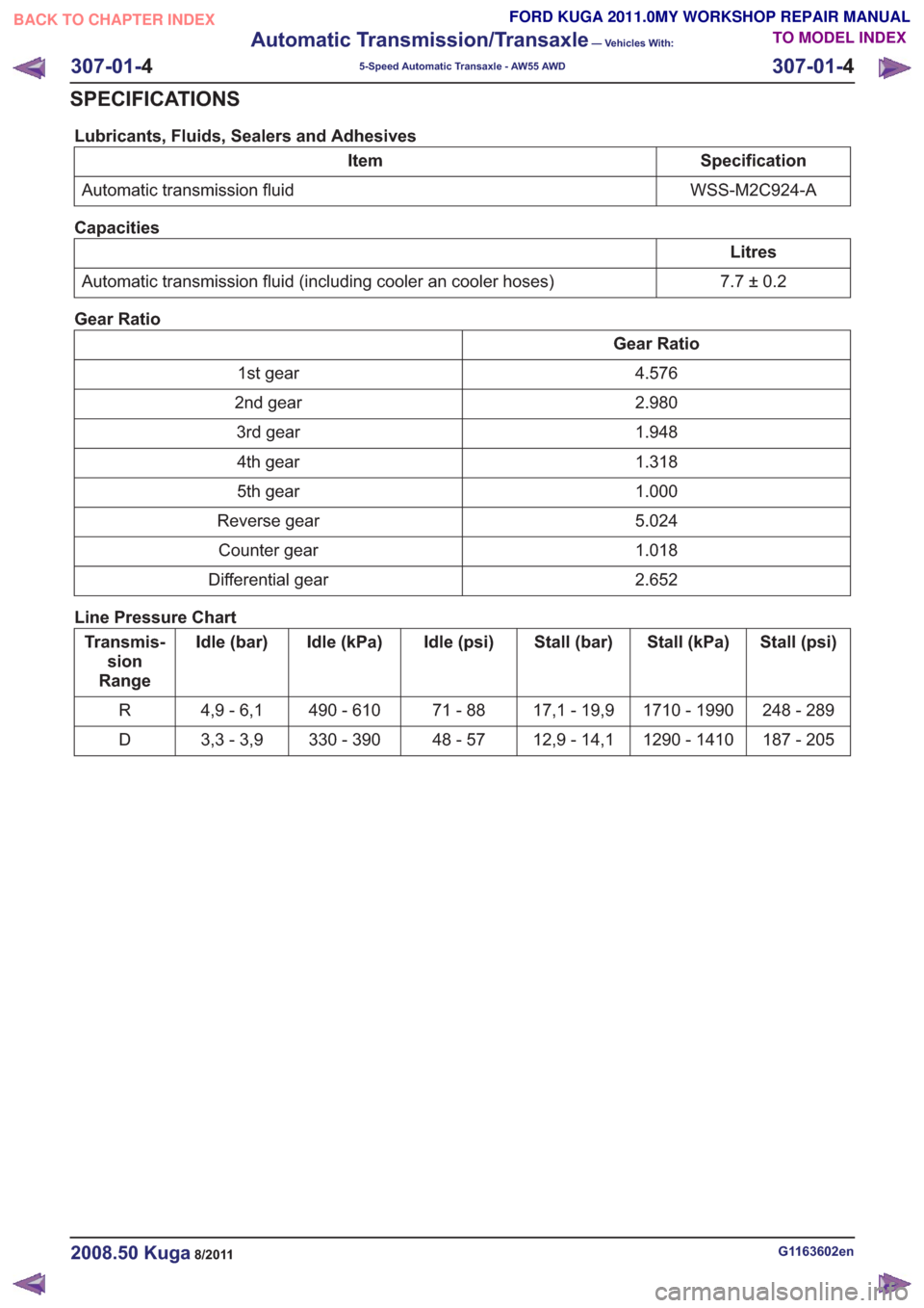
Lubricants, Fluids, Sealers and Adhesives
Specification
Item
WSS-M2C924-A
Automatic transmission fluid
Capacities
Litres
7.7±0.2
Automatic transmission fluid (including cooler an cooler hoses)
Gear Ratio
Gear Ratio 4.576
1st gear
2.980
2nd gear
1.948
3rd gear
1.318
4th gear
1.000
5th gear
5.024
Reverse gear
1.018
Counter gear
2.652
Differential gear
Line Pressure Chart
Stall (psi)
Stall (kPa)
Stall (bar)
Idle (psi)
Idle (kPa)
Idle (bar)
Transmis-
sion
Range
248 - 289
1710 - 1990
17,1 - 19,9
71 - 88
490 - 610
4,9 - 6,1
R
187 - 205
1290 - 1410
12,9 - 14,1
48 - 57
330 - 390
3,3 - 3,9
D
G1163602en2008.50 Kuga8/2011
307-01- 4
Automatic Transmission/Transaxle
— Vehicles With:
5-Speed Automatic Transaxle - AW55 AWD
307-01- 4
SPECIFICATIONS
TO MODEL INDEX
BACK TO CHAPTER INDEX
FORD KUGA 2011.0MY WORKSHOP REPAIR MANUAL
Page 1826 of 2057
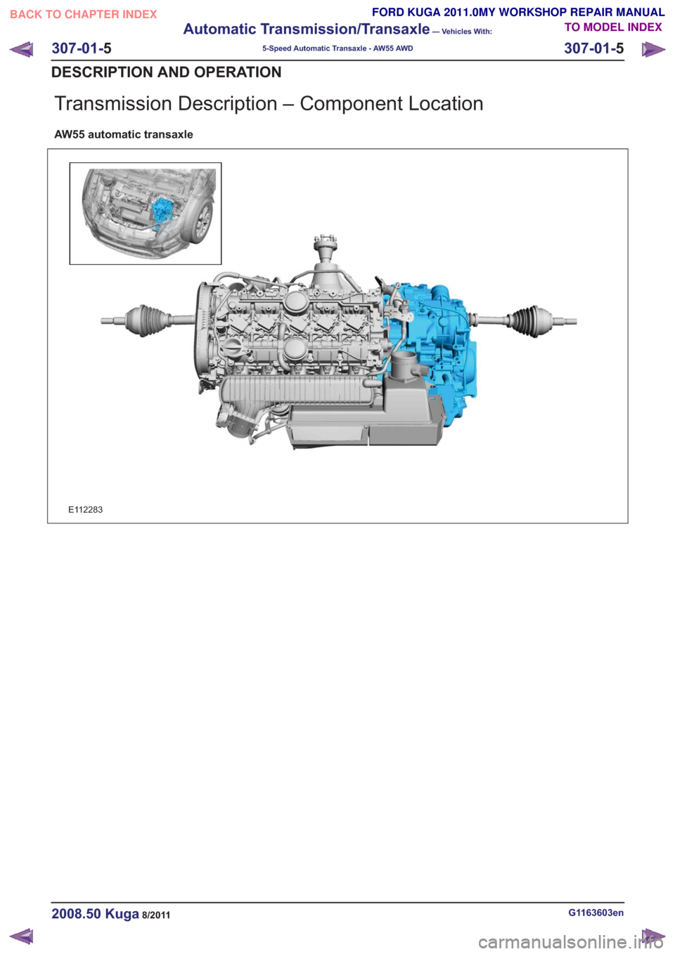
Transmission Description – Component Location
AW55 automatic transaxle
E112283
G1163603en2008.50 Kuga8/2011
307-01-5
Automatic Transmission/Transaxle
— Vehicles With:
5-Speed Automatic Transaxle - AW55 AWD
307-01- 5
DESCRIPTION AND OPERATION
TO MODEL INDEX
BACK TO CHAPTER INDEX
FORD KUGA 2011.0MY WORKSHOP REPAIR MANUAL
Page 1827 of 2057
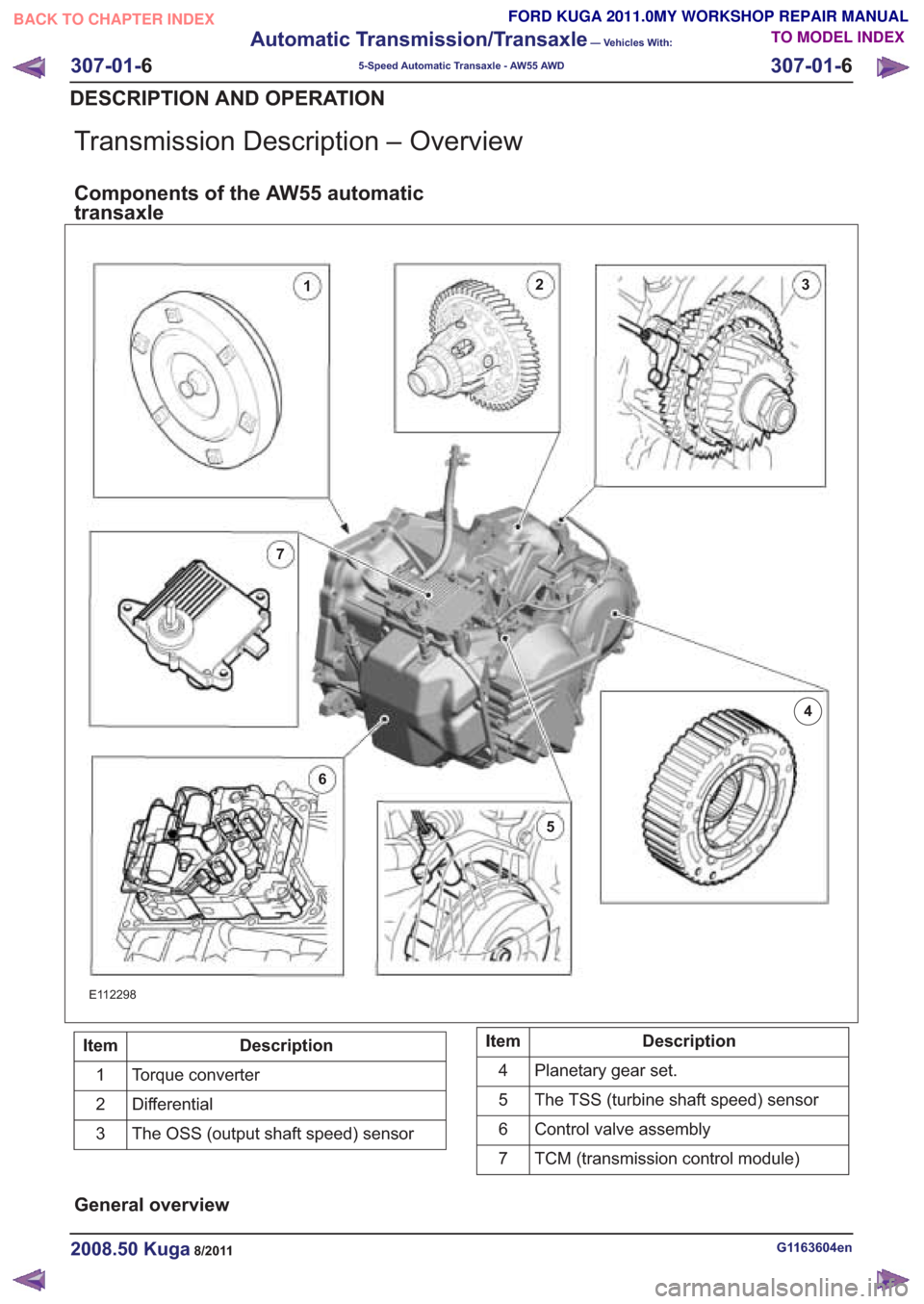
Transmission Description – Overview
Components of the AW55 automatic
transaxle
E112298
Description
Item
Torque converter
1
Differential
2
The OSS (output shaft speed) sensor
3Description
Item
Planetary gear set.
4
The TSS (turbine shaft speed) sensor
5
Control valve assembly
6
TCM (transmission control module)
7
General overview
G1163604en2008.50 Kuga8/2011
307-01- 6
Automatic Transmission/Transaxle
— Vehicles With:
5-Speed Automatic Transaxle - AW55 AWD
307-01- 6
DESCRIPTION AND OPERATION
TO MODEL INDEX
BACK TO CHAPTER INDEX
FORD KUGA 2011.0MY WORKSHOP REPAIR MANUAL
23
4
5
6
7
1
Page 1828 of 2057
E125525
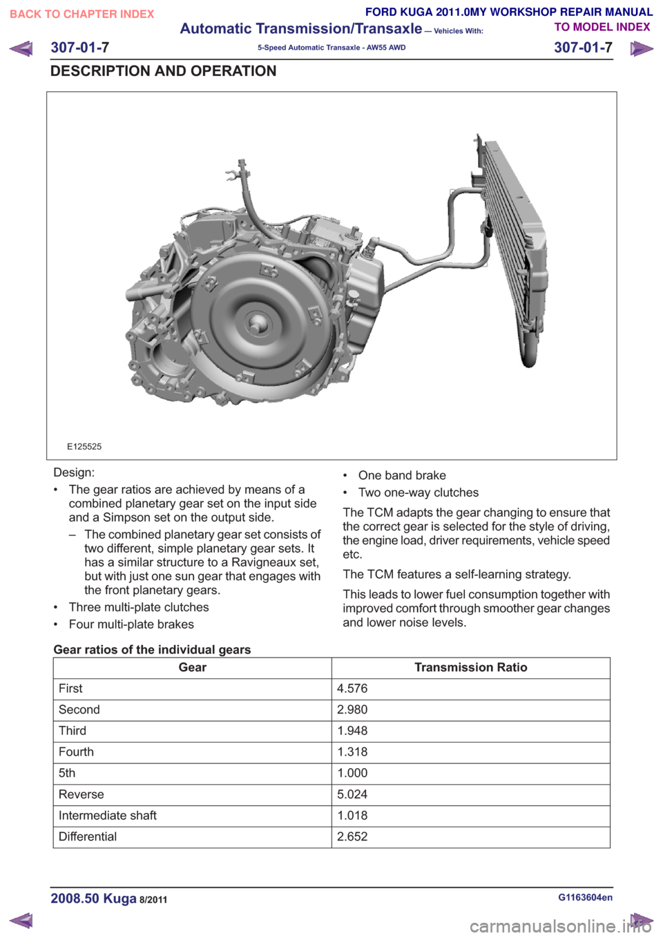
Design:
• The gear ratios are achieved by means of acombined planetary gear set on the input side
and a Simpson set on the output side.
– The combined planetary gear set consists oftwo different, simple planetary gear sets. It
has a similar structure to a Ravigneaux set,
but with just one sun gear that engages with
the front planetary gears.
• Three multi-plate clutches
• Four multi-plate brakes • One band brake
• Two one-way clutches
The TCM adapts the gear changing to ensure that
the correct gear is selected for the style of driving,
the engine load, driver requirements, vehicle speed
etc.
The TCM features a self-learning strategy.
This leads to lower fuel consumption together with
improved comfort through smoother gear changes
and lower noise levels.
Gear ratios of the individual gears
Transmission Ratio
Gear
4.576
First
2.980
Second
1.948
Third
1.318
Fourth
1.000
5th
5.024
Reverse
1.018
Intermediate shaft
2.652
Differential
G1163604en2008.50 Kuga8/2011
307-01- 7
Automatic Transmission/Transaxle
— Vehicles With:
5-Speed Automatic Transaxle - AW55 AWD
307-01- 7
DESCRIPTION AND OPERATION
TO MODEL INDEX
BACK TO CHAPTER INDEX
FORD KUGA 2011.0MY WORKSHOP REPAIR MANUAL