Page 1816 of 2057
Mass Air Flow (MAF) Sensor(29 226 0)
Removal
NOTE:Removal steps in this procedure may
contain installation details.
1. Torque: 10
Nm
E106250
x2
Installation
1.To install, reverse the removal.
G1079138en2008.50 Kuga8/2011
303-14- 42
Electronic Engine Controls— 2.5L Duratec (147kW/200PS) - VI5303-14-
42
REMOVAL AND INSTALLATION
TO MODEL INDEX
BACK TO CHAPTER INDEX
FORD KUGA 2011.0MY WORKSHOP REPAIR MANUAL
Page 1817 of 2057

Powertrain Control Module (PCM)(29 200 0)
General Equipment3.5 mm Drill Bit
Center Punch
Ford Diagnostic Equipment
Removal
NOTE: Removal steps in this procedure may
contain installation details.
1. NOTE: This step is only necessary when
installing a new component.
Download the PCM and throttle body
configuration information into the diagnostic tool,
using the Programmable Modules Installation
routine.
General Equipment: Ford Diagnostic Equipment
2. Refer to: Battery Disconnect and Connect
(414-01 Battery, Mounting and Cables,
General Procedures).
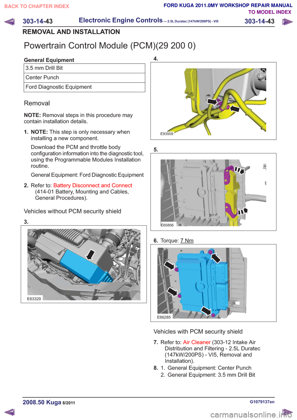
Vehicles without PCM security shield
3.
E63329
4.
E93509
5.
E65856
6. Torque: 7Nm
E66285
Vehicles with PCM security shield
7.Refer to: Air Cleaner (303-12 Intake Air
Distribution and Filtering - 2.5L Duratec
(147kW/200PS) - VI5, Removal and
Installation).
8. General Equipment: Center Punch
1.
2. General Equipment: 3.5 mm Drill Bit
G1079137en2008.50 Kuga8/2011
303-14- 43
Electronic Engine Controls— 2.5L Duratec (147kW/200PS) - VI5303-14-
43
REMOVAL AND INSTALLATION
TO MODEL INDEX
BACK TO CHAPTER INDEX
FORD KUGA 2011.0MY WORKSHOP REPAIR MANUAL
Page 1818 of 2057
E923483
1
2
4
x2
9.
E65361
Installation
1.To install, reverse the removal.
Vehicles with PCM security shield
2.Tighten the shear bolt until the shear bolt head
is sheared off.
E92350
All vehicles
3. NOTE: This step is only necessary when
installing a new component.
Upload the PCM and throttle body configuration
information into the PCM, using the
Programmable Modules Installation routine.
General Equipment: Ford Diagnostic Equipment
G1079137en2008.50 Kuga8/2011
303-14- 44
Electronic Engine Controls— 2.5L Duratec (147kW/200PS) - VI5303-14-
44
REMOVAL AND INSTALLATION
TO MODEL INDEX
BACK TO CHAPTER INDEX
FORD KUGA 2011.0MY WORKSHOP REPAIR MANUAL
Page 1819 of 2057
Variable Valve Timing (VVT) Oil Control Solenoid(29 233 0)
Removal
NOTE:Removal steps in this procedure may
contain installation details.
1. Torque: 10
Nm
x2x2
E92954
2.Torque: 10Nm
E67949
Installation
1.To install, reverse the removal procedure.
G970800en2008.50 Kuga8/2011
303-14- 45
Electronic Engine Controls— 2.5L Duratec (147kW/200PS) - VI5303-14-
45
REMOVAL AND INSTALLATION
TO MODEL INDEX
BACK TO CHAPTER INDEX
FORD KUGA 2011.0MY WORKSHOP REPAIR MANUAL
Page 1820 of 2057
Brake Pedal Position (BPP) Switch(33 502 0)
Removal
1. CAUTION: Make sure that the brakepedal remains in the rest position.
E101878
Installation
1.CAUTION: Make sure that the brake
pedal remains in the rest position.
To install, reverse the removal procedure.
G1065472en2008.50 Kuga8/2011
303-14- 46
Electronic Engine Controls— 2.5L Duratec (147kW/200PS) - VI5303-14-
46
REMOVAL AND INSTALLATION
TO MODEL INDEX
BACK TO CHAPTER INDEX
FORD KUGA 2011.0MY WORKSHOP REPAIR MANUAL
Page 1821 of 2057
Clutch Pedal Position (CPP) Switch(33 503 0)
Removal
1. CAUTION: Make sure that the clutchpedal remains in the rest position.
2
451
E101866
Installation
1.CAUTION: Make sure that the clutch
pedal remains in the rest position.
To install, reverse the removal procedure.
G1065474en2008.50 Kuga8/2011
303-14- 47
Electronic Engine Controls— 2.5L Duratec (147kW/200PS) - VI5303-14-
47
REMOVAL AND INSTALLATION
TO MODEL INDEX
BACK TO CHAPTER INDEX
FORD KUGA 2011.0MY WORKSHOP REPAIR MANUAL
Page 1830 of 2057

1
234
5
6
8
9
7
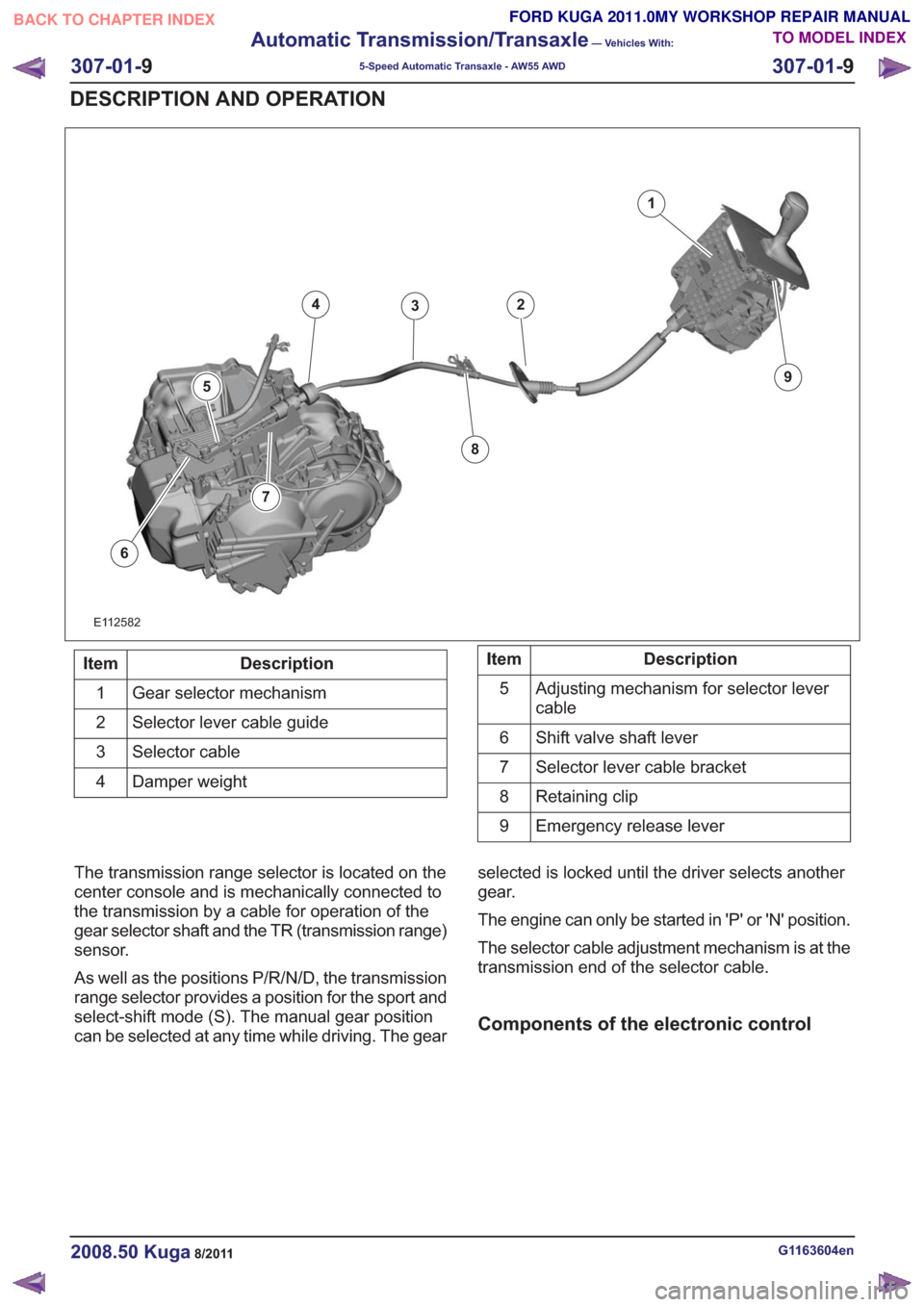
E112582
Description
Item
Gear selector mechanism
1
Selector lever cable guide
2
Selector cable
3
Damper weight
4Description
Item
Adjusting mechanism for selector lever
cable
5
Shift valve shaft lever
6
Selector lever cable bracket
7
Retaining clip
8
Emergency release lever
9
The transmission range selector is located on the
center console and is mechanically connected to
the transmission by a cable for operation of the
gear selector shaft and the TR (transmission range)
sensor.
As well as the positions P/R/N/D, the transmission
range selector provides a position for the sport and
select-shift mode (S). The manual gear position
can be selected at any time while driving. The gear selected is locked until the driver selects another
gear.
The engine can only be started in 'P' or 'N' position.
The selector cable adjustment mechanism is at the
transmission end of the selector cable.
Components of the electronic control
G1163604en2008.50 Kuga8/2011
307-01-
9
Automatic Transmission/Transaxle
— Vehicles With:
5-Speed Automatic Transaxle - AW55 AWD
307-01- 9
DESCRIPTION AND OPERATION
TO MODEL INDEX
BACK TO CHAPTER INDEX
FORD KUGA 2011.0MY WORKSHOP REPAIR MANUAL
Page 1831 of 2057

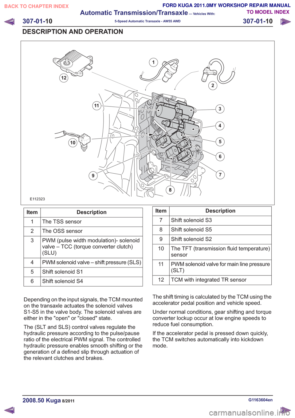
E112323
1
2
7
6
4
5
3
10
9
11
12
Description
Item
The TSS sensor
1
The OSS sensor
2
PWM (pulse width modulation)- solenoid
valve – TCC (torque converter clutch)
(SLU)
3
PWM solenoid valve – shift pressure (SLS)
4
Shift solenoid S1
5
Shift solenoid S4
6Description
Item
Shift solenoid S3
7
Shift solenoid S5
8
Shift solenoid S2
9
The TFT (transmission fluid temperature)
sensor
10
PWM solenoid valve for main line pressure
(SLT)
11
TCM with integrated TR sensor
12
Depending on the input signals, the TCM mounted
on the transaxle actuates the solenoid valves
S1-S5 in the valve body. The solenoid valves are
either in the "open" or "closed" state.
The (SLT and SLS) control valves regulate the
hydraulic pressure according to the pulse/pause
ratio of the electrical PWM signal. The controlled
hydraulic pressure enables smooth shifting or the
generation of a defined slip through actuation of
the relevant clutches and brakes. The shift timing is calculated by the TCM using the
accelerator pedal position and vehicle speed.
Under normal conditions, gear shifting and torque
converter lockup occur at low engine speeds to
reduce fuel consumption.
If the accelerator pedal is pressed down quickly,
the TCM switches automatically into kickdown
mode.
G1163604en2008.50 Kuga8/2011
307-01-
10
Automatic Transmission/Transaxle
— Vehicles With:
5-Speed Automatic Transaxle - AW55 AWD
307-01- 10
DESCRIPTION AND OPERATION
TO MODEL INDEX
BACK TO CHAPTER INDEX
FORD KUGA 2011.0MY WORKSHOP REPAIR MANUAL