Page 170 of 2057
Auxiliary Coolant Flow Pump
General Equipment
Hose Clamp(s) General Equipment
Hose Clamp Remover/Installer
Removal
1. Refer to: Engine Cooling System Health and
Safety Precautions (100-00 General
Information, Description and Operation).
2. Refer to: Jacking(100-02 Jacking and Lifting,
Description and Operation).
3. General Equipment: Hose Clamp(s)
General Equipment: Hose Clamp
Remover/Installer Installation
1.
To install, reverse the removal procedure.
2. Check the coolant level.
Refer to: Cooling System Draining and Vacuum
Filling (303-03 Engine Cooling, General
Procedures). G1163562en
2008.50 Kuga 8/2011 412-02-17
Auxiliary Climate Control
412-02-17
REMOVAL AND INSTALLATIONTO MODEL INDEX
BACK TO CHAPTER INDEX
FORD KUGA 2011.0MY WORKSHOP REPAIR MANUAL11E112651
Page 174 of 2057
Fuel Fired Booster Heater — 2.5L Duratec (147kW/200PS) - VI5
General Equipment
Hose Clamp(s) General Equipment
Hose Clamp Remover/Installer
Removal
NOTE: Removal steps in this procedure may
contain installation details. 1.
Refer to: Engine Cooling System Health and
Safety Precautions (100-00 General
Information, Description and Operation).
Refer to: Petrol and Petrol-Ethanol Fuel
Systems Health and Safety Precautions
(100-00 General Information, Description and
Operation).
2. Refer to: Lifting(100-02 Jacking and Lifting,
Description and Operation).
3. G1163563en
2008.50 Kuga 8/2011 412-02-21
Auxiliary Climate Control
412-02-21
REMOVAL AND INSTALLATIONTO MODEL INDEX
BACK TO CHAPTER INDEX
FORD KUGA 2011.0MY WORKSHOP REPAIR MANUALE112641
Page 178 of 2057
Fuel Fired Booster Heater Fuel Pump
Removal
1.
Refer to: Petrol and Petrol-Ethanol Fuel
Systems Health and Safety Precautions
(100-00 General Information, Description and
Operation).
2. Refer to: Fuel Tank - 2.5L Duratec
(147kW/200PS) - VI5 (310-01 Fuel Tank and
Lines, Removal and Installation).
3. Refer to: Quick Release Coupling (310-00 Fuel
System - General Information, General
Procedures). Installation
1.
To install, reverse the removal procedure. G1163564en
2008.50 Kuga 8/2011 412-02-25
Auxiliary Climate Control
412-02-25
REMOVAL AND INSTALLATIONTO MODEL INDEX
BACK TO CHAPTER INDEX
FORD KUGA 2011.0MY WORKSHOP REPAIR MANUALE112750
Page 179 of 2057
Fuel Fired Booster Heater
General Equipment
Flat-bladed screwdriver
Disassembly
NOTE: Removal steps in this procedure may
contain installation details.
1. Refer to: Engine Cooling System Health and
Safety Precautions (100-00 General
Information, Description and Operation).
2. 3. 4.
5.
6.
G1163567en
2008.50 Kuga 8/2011 412-02-26
Auxiliary Climate Control
412-02-26
DISASSEMBLY AND ASSEMBLYTO MODEL INDEX
BACK TO CHAPTER INDEX
FORD KUGA 2011.0MY WORKSHOP REPAIR MANUALx4E112695 E112696x4 E112697 E112698x4 E112699
Page 192 of 2057
Instrument Cluster
General Equipment
Ford Diagnostic Equipment General Equipment
Round-Ended Steel Rule
Removal
1. NOTE: This step is only necessary when
installing a new component.
Upload the instrument cluster configuration
information using the Programmable Modules
Installation Routine.
General Equipment: Ford Diagnostic Equipment
2. NOTE: This step is only necessary when
installing a new component.
Record the odometer value from the original
instrument cluster. If the odometer value cannot
be obtained from the instrument cluster (display
failure), the customer should supply the
approximate odometer value.
3. 4.
5.
General Equipment: Round-Ended Steel Rule G1065570en
2008.50 Kuga 8/2011 413-01-9
Instrument Cluster
413-01-9
REMOVAL AND INSTALLATIONTO MODEL INDEX
BACK TO CHAPTER INDEX
FORD KUGA 2011.0MY WORKSHOP REPAIR MANUAL12E101806 E100832
Page 270 of 2057

Battery Disconnect and Connect
Disconnect
WARNINGS:
Batteries normally produce explosive
gases which may cause personal injury,
therefore do not allow flames, sparks or
lighted substances to come near the
battery. When charging or working near
the battery always shield your face and
protect your eyes. Always provide
adequate ventilation. Failure to follow
these instructions may result in personal
injury.
The supplemental restraint system (SRS)
is active for a certain length of time after
the power supply has been disconnected.
Wait for a minimum of 3 minutes before
disconnecting or removing any SRS
components.
Audio unit key code saving devices must
not be used when working on
supplemental restraint or fuel systems.
When using these devices the vehicle
electrical system is still live but with a
reduced current flow. Failure to follow this
instruction may result in personal injury.
CAUTION: Make sure the engine is not
running before disconnecting the battery
ground cable to avoid damage to the
vehicle electrical system.
NOTE: Disconnecting the battery will erase fault
codes, drive values and customer data stored in
the modules.
NOTE: This procedure should be used to
disconnect the battery while carrying out repairs
that refer to the battery being disconnected.
1. Refer to: Battery and Battery Charging Health
and Safety Precautions (100-00 General
Information, Description and Operation).
2. Obtain and record the audio unit keycode and
preset radio frequencies. 3.
G1062389en
2008.50 Kuga 8/2011 414-01-2
Battery, Mounting and Cables
414-01-2
GENERAL PROCEDURESTO MODEL INDEX
BACK TO CHAPTER INDEX
FORD KUGA 2011.0MY WORKSHOP REPAIR MANUALE103137
Page 272 of 2057
Battery
Removal
1.
Refer to: Battery and Battery Charging Health
and Safety Precautions (100-00 General
Information, Description and Operation).
2. Refer to: Battery Disconnect and Connect
(414-01 Battery, Mounting and Cables,
General Procedures).
3. Installation
1.
Torque:
• 1 15 Nm
• 2 10 Nm
• 3 12 Nm
2.
Refer to: Battery Disconnect and Connect
(414-01 Battery, Mounting and Cables,
General Procedures). G1065713en
2008.50 Kuga 8/2011 414-01-4
Battery, Mounting and Cables
414-01-4
REMOVAL AND INSTALLATIONTO MODEL INDEX
BACK TO CHAPTER INDEX
FORD KUGA 2011.0MY WORKSHOP REPAIR MANUALE102716123 E102716123
Page 411 of 2057
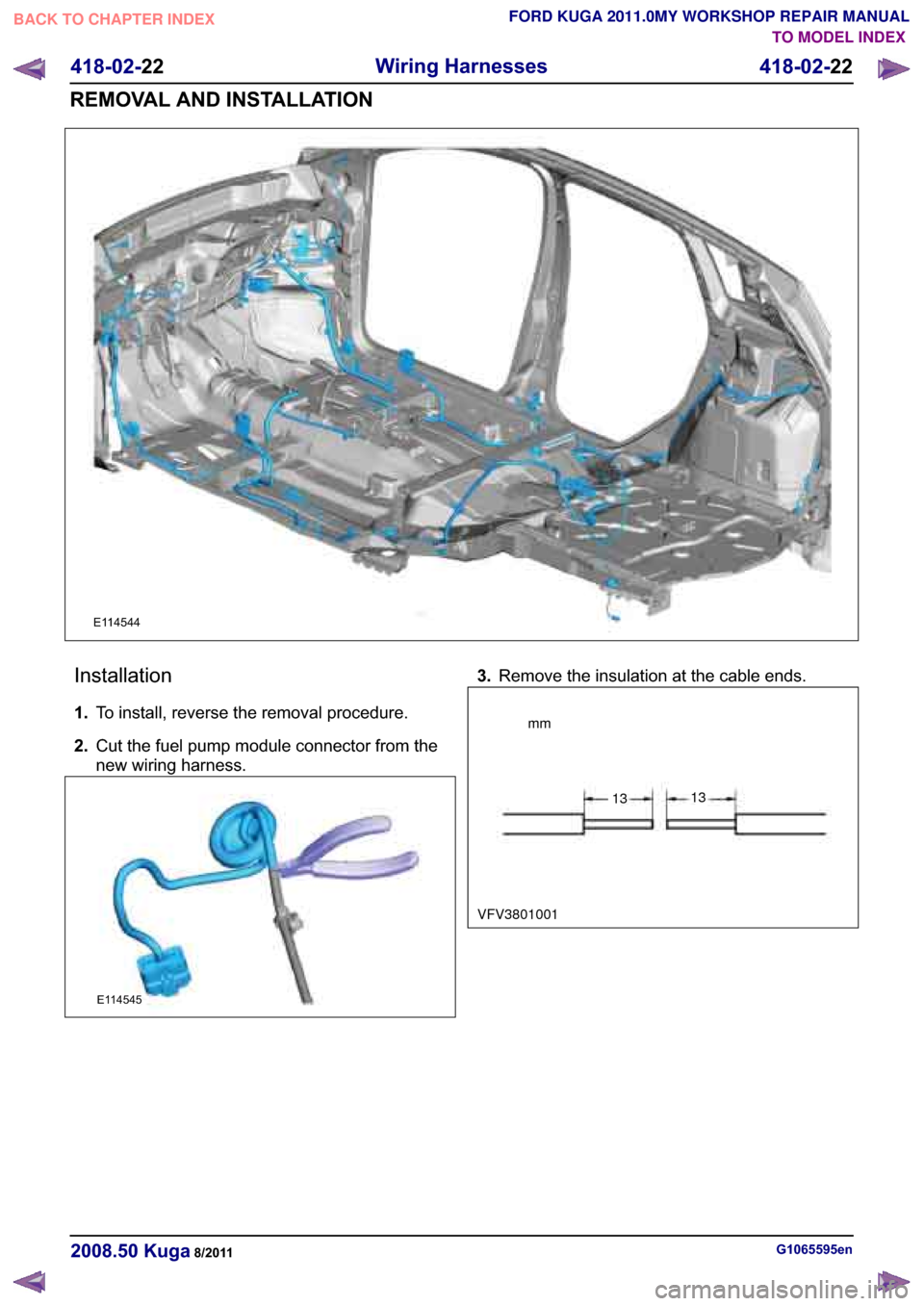
�(������������
�����5�H�P�R�Y�H �W�K�H �L�Q�V�X�O�D�W�L�R�Q �D�W �W�K�H �F�D�E�O�H �H�Q�G�V��
�*���������������H�Q�������������� �.�X�J�D������������
�������������� ����
�:�L�U�L�Q�J �+�D�U�Q�H�V�V�H�V
�������������� ����
�5�(�0�2�9�$�/ �$�1�' �,�1�6�7�$�/�/�$�7�,�2�1
FORD KUGA 2011.0MY WORKSHOP REPAIR MANUAL
TO MODEL INDEX
BACK TO CHAPTER INDEX
VFV3801001
�(������������
�,�Q�V�W�D�O�O�D�W�L�R�Q
���� �7�R �L�Q�V�W�D�O�O�� �U�H�Y�H�U�V�H �W�K�H �U�H�P�R�Y�D�O �S�U�R�F�H�G�X�U�H��
���� �&�X�W �W�K�H �I�X�H�O �S�X�P�S �P�R�G�X�O�H �F�R�Q�Q�H�F�W�R�U �I�U�R�P �W�K�H
�Q�H�Z �Z�L�U�L�Q�J �K�D�U�Q�H�V�V��mm
1313
 General Equipment
Hose Clamp Remover/Installer
Removal
1. Refer to: Engine Cooling System Health and
Safety Precautions (100-00 General
Info")
 - VI5
General Equipment
Hose Clamp(s) General Equipment
Hose Clamp Remover/Installer
Removal
NOTE: Removal steps in this procedure may
contain")
.
2. Refer to: Fuel")


.
2. Refer to: Battery Disconnect and Connect
(414-01 Bat")