Page 1402 of 2057
Brake Master Cylinder — 2.5L Duratec (147kW/200PS) -VI5(12 343 0)
Removal
NOTE: Removal steps in this procedure may
contain installation details.
1. Refer to: Brake System Health and Safety
Precautions (100-00 General Information,
Description and Operation).
2. Connect one end of a suitable piece of clear
plastic pipe to the brake caliper bleed nipple
1.
and place the other end into a suitable
container.
2. Loosen the bleed nipple.
3. Depress the brake pedal until no more brake fluid comes through the bleed nipple.
4. Tighten the bleed nipple.
5. Repeat the draining procedure on the opposite side brake caliper.
E86914
Left-hand drive vehicles
3. CAUTION: Make sure that all openings are sealed.
1. Torque: 18Nm
2.NOTE: Make sure that new components are
installed.
Torque: 25
Nm
G1174985en2008.50 Kuga8/2011
206-06- 5
Hydraulic Brake Actuation
206-06- 5
REMOVAL AND INSTALLATION
TO MODEL INDEX
BACK TO CHAPTER INDEX
FORD KUGA 2011.0MY WORKSHOP REPAIR MANUAL
Page 1404 of 2057
E114811
2
1
Installation
1.To install, reverse the removal procedure.
2. Refer to: Brake System Bleeding (206-00 Brake
System - General Information, General
Procedures).
Refer to: Brake System Pressure Bleeding
(206-00 Brake System - General Information,
General Procedures).
G1174985en2008.50 Kuga8/2011
206-06- 7
Hydraulic Brake Actuation
206-06- 7
REMOVAL AND INSTALLATION
TO MODEL INDEX
BACK TO CHAPTER INDEX
FORD KUGA 2011.0MY WORKSHOP REPAIR MANUAL
Page 1406 of 2057
Brake Booster — 2.5L Duratec (147kW/200PS) - VI5, RHD4WD/RHD FWD(12 451 0)
Removal
NOTE: Removal steps in this procedure may
contain installation details.
1. Refer to: Brake System Health and Safety
Precautions (100-00 General Information,
Description and Operation).
2. Torque: 24
Nm
E69829
x4
1
2
3.Refer to: Air Conditioning (A/C) System
Recovery, Evacuation and Charging (412-00
Climate Control System - General Information,
General Procedures).
Refer to: Brake Master Cylinder - 2.5L Duratec
(147kW/200PS) - VI5 (206-06 Hydraulic Brake
Actuation, Removal and Installation).
Refer to: Lifting(100-02 Jacking and Lifting,
Description and Operation).
4.
E65299
5. Torque:
• Stage 1: 10
Nm
• Stage 2: 25Nm
E99866
x6
6.
G1185955en2008.50 Kuga8/2011
206-07- 2
Power Brake Actuation
206-07- 2
REMOVAL AND INSTALLATION
TO MODEL INDEX
BACK TO CHAPTER INDEX
FORD KUGA 2011.0MY WORKSHOP REPAIR MANUAL
Page 1414 of 2057

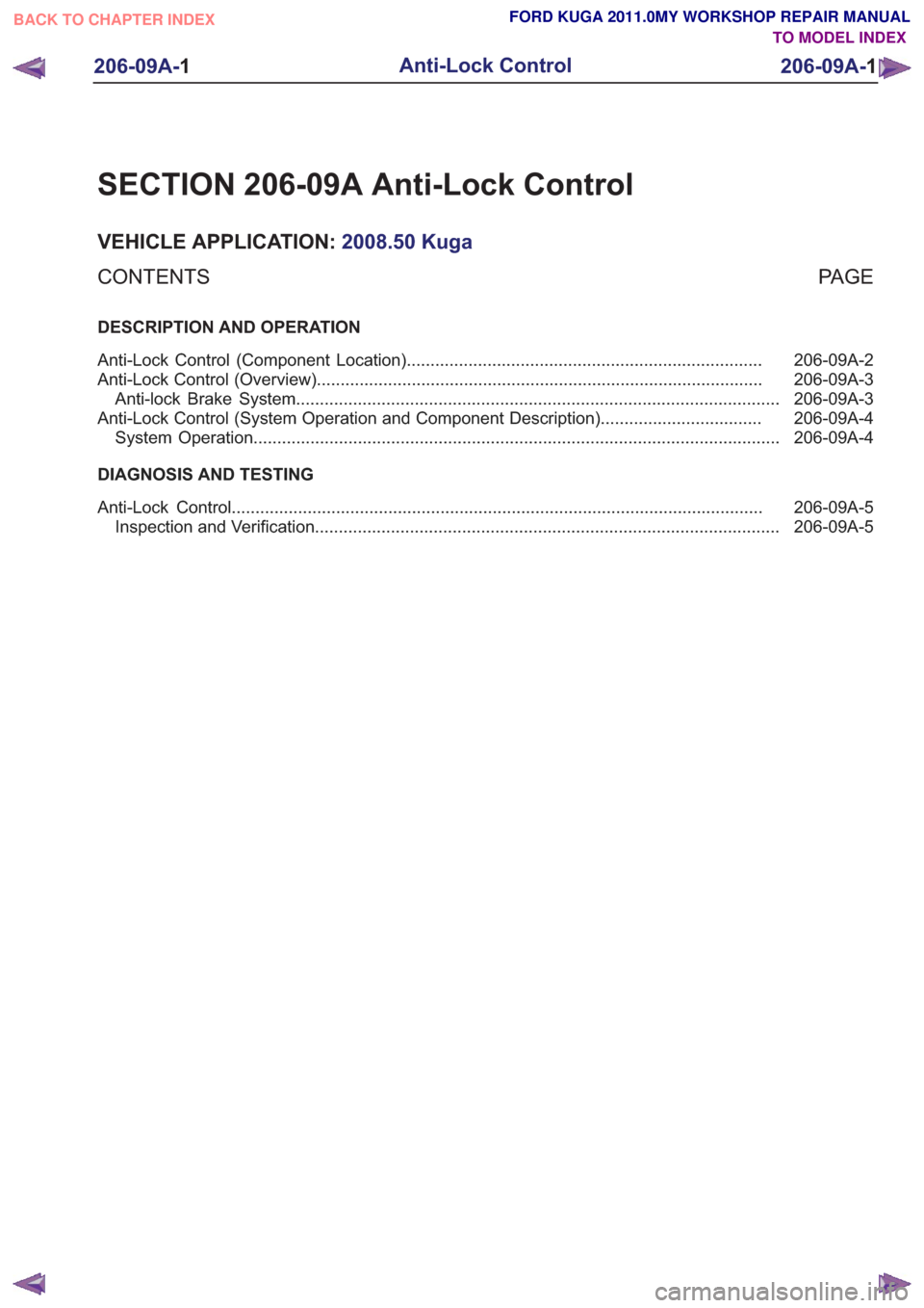
SECTION 206-09A Anti-Lock Control
VEHICLE APPLICATION:2008.50 Kuga
PA G E
CONTENTS
DESCRIPTION AND OPERATION
206-09A-2
Anti-Lock Control (Component Location) ........................................................................\
...
206-09A-3
Anti-Lock Control (Overview) ........................................................................\
......................
206-09A-3
Anti-lock Brake System ........................................................................\
..............................
206-09A-4
Anti-Lock Control (System Operation and Component Description) ..................................
206-09A-4
System Operation ........................................................................\
.......................................
DIAGNOSIS AND TESTING 206-09A-5
Anti-Lock Control ........................................................................\
........................................
206-09A-5
Inspection and Verification ........................................................................\
..........................
206-09A-1
Anti-Lock Control
206-09A- 1
.
TO MODEL INDEX
BACK TO CHAPTER INDEX
FORD KUGA 2011.0MY WORKSHOP REPAIR MANUAL
Page 1415 of 2057
Anti-Lock Control – Component Location
NOTE:
Refer to:Brake System (206-00 Brake System -
General Information, Description and Operation).
E96610
G1001298en2008.50 Kuga8/2011
206-09A- 2
Anti-Lock Control
206-09A- 2
DESCRIPTION AND OPERATION
TO MODEL INDEX
BACK TO CHAPTER INDEX
FORD KUGA 2011.0MY WORKSHOP REPAIR MANUAL
Page 1416 of 2057
Anti-Lock Control – Overview
Anti-lock Brake System
Refer to:Anti-Lock Control - Stability Assist (206-09
Anti-Lock Control - Stability Assist, Description
and Operation).
G1001218en2008.50 Kuga8/2011
206-09A- 3
Anti-Lock Control
206-09A- 3
DESCRIPTION AND OPERATION
TO MODEL INDEX
BACK TO CHAPTER INDEX
FORD KUGA 2011.0MY WORKSHOP REPAIR MANUAL
Page 1418 of 2057
Anti-Lock Control
schematic
and connector information.
General Equipment
The Ford approved diagnostic tool
Inspection and Verification
1. Verify the customer concern.
2. Visually inspect for obvious signs of mechanical or electrical damage.
Visual Inspection Chart
Electrical
Mechanical
• Fuse(s)
• Electricalconnector(s)
• Wiring harness(s).
• Anti-lock brake system (ABS)
module
• Wheel speed
sensor(s)
• Wheel speed sensor ring(s)
3. If an obvious cause for an observed or reported concern is found, correct the cause (if possible)
before proceeding to the next step.
4. If the cause is not visually evident, verify the symptom and refer to the diagnostic tab within
the Ford approved diagnostic tool.
G1058976en2008.50 Kuga8/2011
206-09A- 5
Anti-Lock Control
206-09A- 5
DIAGNOSIS AND TESTING
TO MODEL INDEX
BACK TO CHAPTER INDEX
FORD KUGA 2011.0MY WORKSHOP REPAIR MANUAL
Refer to
Wiring Diagrams Section 206-09A, for
Page 1419 of 2057

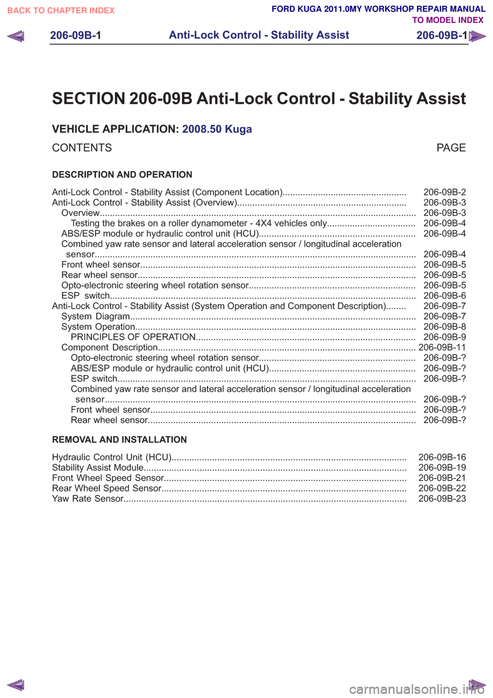
SECTION 206-09B Anti-Lock Control - Stability Assist
VEHICLE APPLICATION:2008.50 Kuga
PA G E
CONTENTS
DESCRIPTION AND OPERATION
206-09B-2
Anti-Lock Control - Stability Assist (Component Location) .................................................
206-09B-3
Anti-Lock Control - Stability Assist (Overview) ...................................................................
206-09B-3
Overview ........................................................................\
.....................................................
206-09B-4
Testing the brakes on a roller dynamometer - 4X4 vehicles only ...................................
206-09B-4
ABS/ESP module or hydraulic control unit (HCU) ..............................................................
206-09B-4
Combined yaw rate sensor and lateral acceleration sensor / longitudinal acceleration
sensor ........................................................................\
.......................................................
206-09B-5
Front wheel sensor ........................................................................\
.....................................
206-09B-5
Rear wheel sensor ........................................................................\
......................................
206-09B-5
Opto-electronic steering wheel rotation sensor ..................................................................
206-09B-6
ESP switch ........................................................................\
.................................................
206-09B-7
Anti-Lock Control - Stability Assist (System Operation and Component Description) ........
206-09B-7
System Diagram ........................................................................\
.........................................
206-09B-8
System Operation ........................................................................\
.......................................
206-09B-9
PRINCIPLES OF OPERATION ........................................................................\
...............
206-09B-11
Component Description ........................................................................\
..............................
206-09B-?
Opto-electronic steering wheel rotation sensor ..............................................................
206-09B-?
ABS/ESP module or hydraulic control unit (HCU) ..........................................................
206-09B-?
ESP switch ........................................................................\
..............................................
206-09B-?
Combined yaw rate sensor and lateral acceleration sensor / longitudinal acceleration
sensor........................................................................\
................................................... 206-09B-?
Front wheel sensor ........................................................................\
.................................
206-09B-?
Rear wheel sensor ........................................................................\
..................................
REMOVAL AND INSTALLATION 206-09B-16
Hydraulic Control Unit (HCU) ........................................................................\
.....................
206-09B-19
Stability Assist Module ........................................................................\
................................
206-09B-21
Front Wheel Speed Sensor ........................................................................\
........................
206-09B-22
Rear Wheel Speed Sensor ........................................................................\
.........................
206-09B-23
Yaw Rate Sensor ........................................................................\
........................................
206-09B-1
Anti-Lock Control - Stability Assist
206-09B- 1
.
TO MODEL INDEX
BACK TO CHAPTER INDEX
FORD KUGA 2011.0MY WORKSHOP REPAIR MANUAL