2011 FORD KUGA Sensor
[x] Cancel search: SensorPage 1467 of 2057
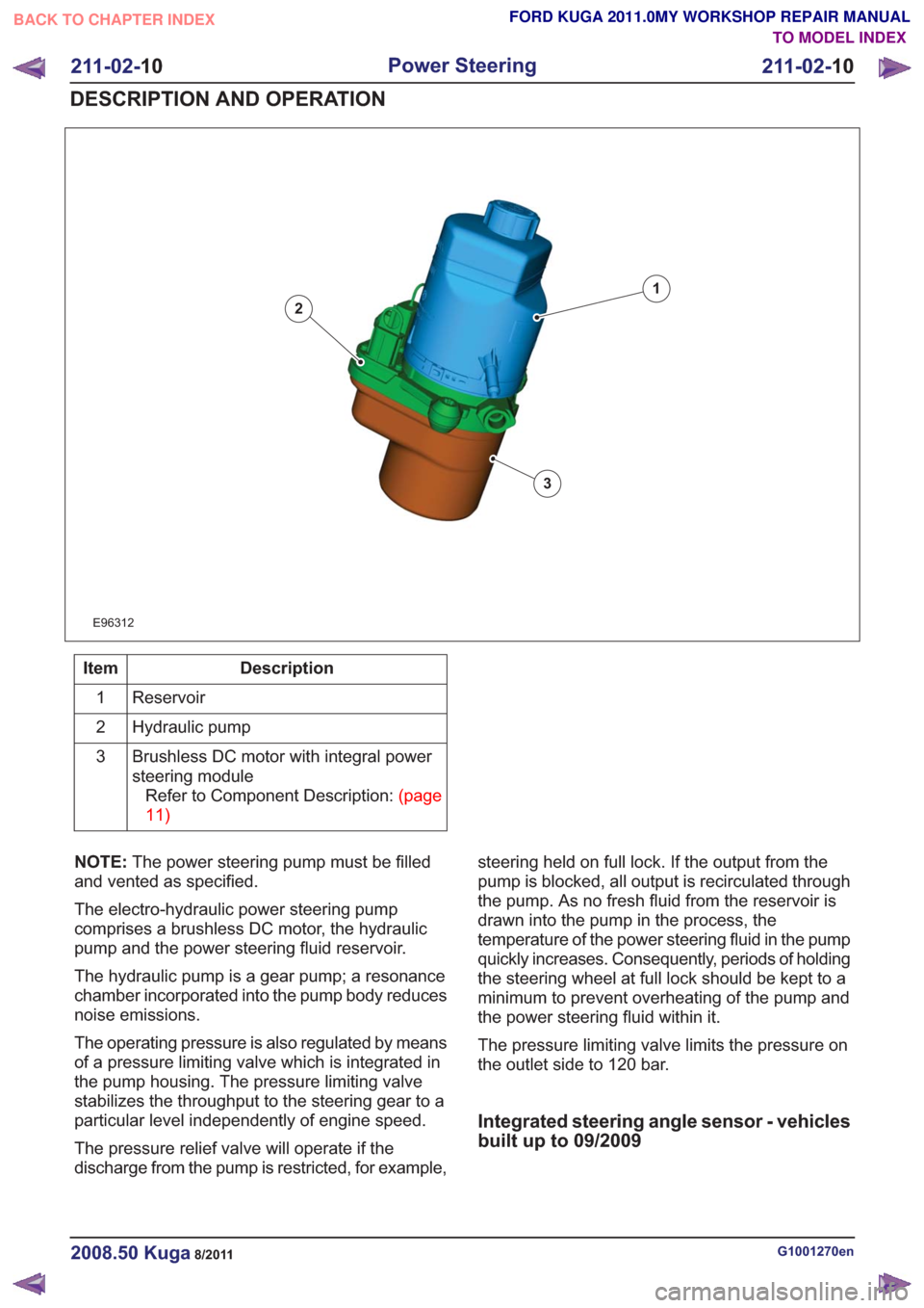
E96312
1
2
3
Description
Item
Reservoir
1
Hydraulic pump
2
Brushless DC motor with integral power
steering moduleRefertoComponentDescription:(page
11)
3
NOTE: The power steering pump must be filled
and vented as specified.
The electro-hydraulic power steering pump
comprises a brushless DC motor, the hydraulic
pump and the power steering fluid reservoir.
The hydraulic pump is a gear pump; a resonance
chamber incorporated into the pump body reduces
noise emissions.
The operating pressure is also regulated by means
of a pressure limiting valve which is integrated in
the pump housing. The pressure limiting valve
stabilizes the throughput to the steering gear to a
particular level independently of engine speed.
The pressure relief valve will operate if the
discharge from the pump is restricted, for example, steering held on full lock. If the output from the
pump is blocked, all output is recirculated through
the pump. As no fresh fluid from the reservoir is
drawn into the pump in the process, the
temperature of the power steering fluid in the pump
quickly increases. Consequently, periods of holding
the steering wheel at full lock should be kept to a
minimum to prevent overheating of the pump and
the power steering fluid within it.
The pressure limiting valve limits the pressure on
the outlet side to 120 bar.
Integrated steering angle sensor - vehicles
built up to 09/2009
G1001270en2008.50 Kuga8/2011
211-02-
10
Power Steering
211-02- 10
DESCRIPTION AND OPERATION
TO MODEL INDEX
BACK TO CHAPTER INDEX
FORD KUGA 2011.0MY WORKSHOP REPAIR MANUAL
Page 1468 of 2057
E96430
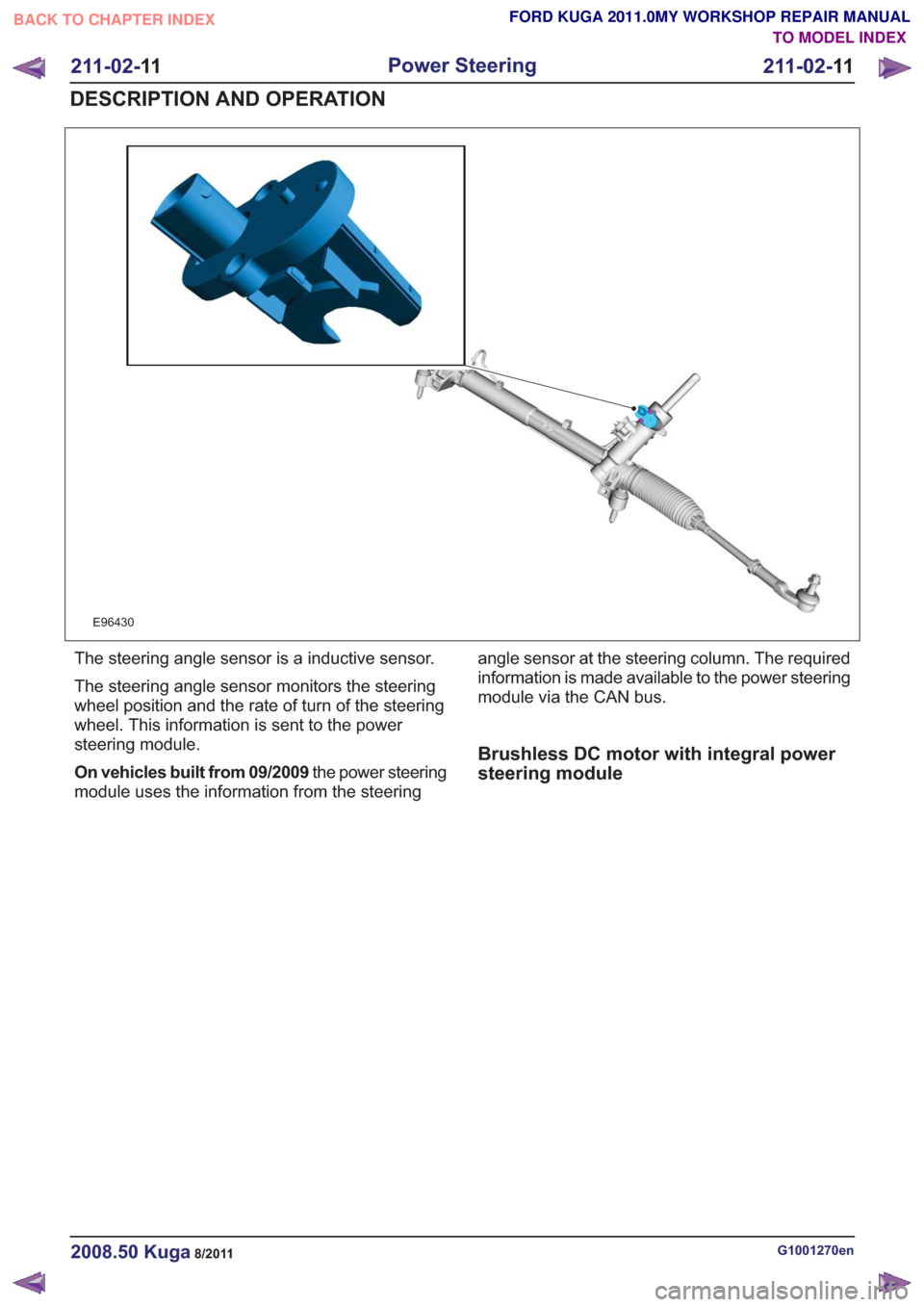
The steering angle sensor is a inductive sensor.
The steering angle sensor monitors the steering
wheel position and the rate of turn of the steering
wheel. This information is sent to the power
steering module.
On vehicles built from 09/2009the power steering
module uses the information from the steering angle sensor at the steering column. The required
information is made available to the power steering
module via the CAN bus.
Brushless DC motor with integral power
steering module
G1001270en2008.50 Kuga8/2011
211-02-
11
Power Steering
211-02- 11
DESCRIPTION AND OPERATION
TO MODEL INDEX
BACK TO CHAPTER INDEX
FORD KUGA 2011.0MY WORKSHOP REPAIR MANUAL
Page 1511 of 2057

Steering Column Switches – Overview
Switch unit, steering column
E98629
1
2
3
4
5
Description
Item
Left-hand switch, steering column
1
Switch unit carrier, steering column
2
Right-hand switch, steering column
3Description
Item
Steering wheel rotation sensor
Refer to: Anti-Lock Control - Stability
Assist (206-09 Anti-Lock Control -
Stability Assist, Description and
Operation).
4
Clockspring
5
Clockspring
The clockspring is designed to carry signals
between the RCM and the driver air bag module.
The clockspring is installed on the steering column,
and consists of fixed and moving parts connected
by a coiled Mylar tape with internal conducting
tracks. The Mylar tape is able to 'wind up' and
'unwind' as the steering wheel is rotated,
maintaining electrical contact at all times between
the RCM and the driver air bag module. During removal and installation or renewal of the
clockspring, pay attention to the following:
• Before installation of the clockspring, it must be
aligned according to the installation instructions.
• Make sure that the vehicle electrical system is fully depowered and no other power source is
connected.
• Secure the clockspring rotor with adhesive tape to the clockspring outer.
• The clockspring rotor must not be turned during removal or installation of the steering wheel or
the steering column switch unit.
G1030755en2008.50 Kuga8/2011
211-05- 3
Steering Column Switches
211-05- 3
DESCRIPTION AND OPERATION
TO MODEL INDEX
BACK TO CHAPTER INDEX
FORD KUGA 2011.0MY WORKSHOP REPAIR MANUAL
Page 1539 of 2057
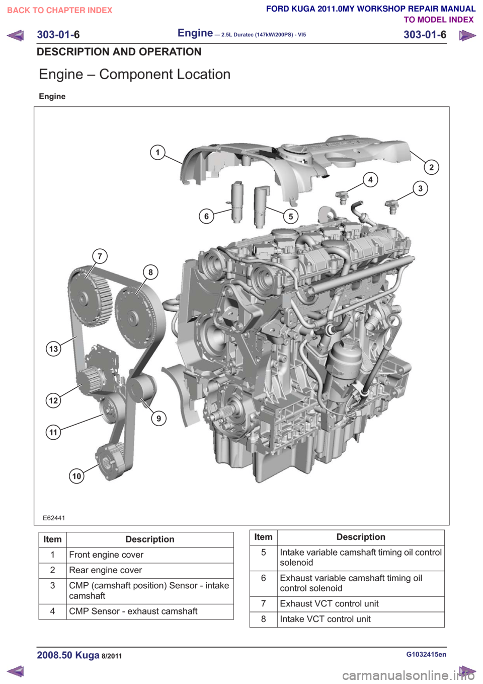
Engine – Component Location
Engine
E62441
1
65
4
3
2
9
10
13
12
11
8
7
Description
Item
Front engine cover
1
Rear engine cover
2
CMP (camshaft position) Sensor - intake
camshaft
3
CMP Sensor - exhaust camshaft
4Description
Item
Intake variable camshaft timing oil control
solenoid
5
Exhaust variable camshaft timing oil
control solenoid
6
Exhaust VCT control unit
7
Intake VCT control unit
8
G1032415en2008.50 Kuga8/2011
303-01- 6
Engine— 2.5L Duratec (147kW/200PS) - VI5303-01-
6
DESCRIPTION AND OPERATION
TO MODEL INDEX
BACK TO CHAPTER INDEX
FORD KUGA 2011.0MY WORKSHOP REPAIR MANUAL
Page 1546 of 2057
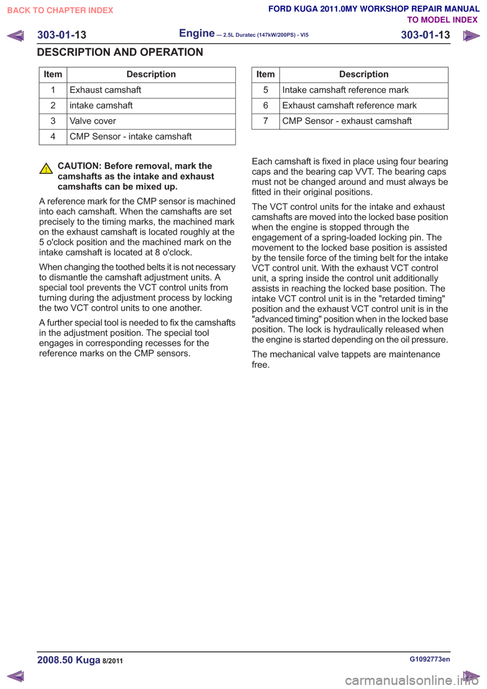
Description
Item
Exhaust camshaft
1
intake camshaft
2
Valve cover
3
CMP Sensor - intake camshaft
4Description
Item
Intake camshaft reference mark
5
Exhaust camshaft reference mark
6
CMP Sensor - exhaust camshaft
7
CAUTION: Before removal, mark the
camshafts as the intake and exhaust
camshafts can be mixed up.
A reference mark for the CMP sensor is machined
into each camshaft. When the camshafts are set
precisely to the timing marks, the machined mark
on the exhaust camshaft is located roughly at the
5 o'clock position and the machined mark on the
intake camshaft is located at 8 o'clock.
When changing the toothed belts it is not necessary
to dismantle the camshaft adjustment units. A
special tool prevents the VCT control units from
turning during the adjustment process by locking
the two VCT control units to one another.
A further special tool is needed to fix the camshafts
in the adjustment position. The special tool
engages in corresponding recesses for the
reference marks on the CMP sensors. Each camshaft is fixed in place using four bearing
caps and the bearing cap VVT. The bearing caps
must not be changed around and must always be
fitted in their original positions.
The VCT control units for the intake and exhaust
camshafts are moved into the locked base position
when the engine is stopped through the
engagement of a spring-loaded locking pin. The
movement to the locked base position is assisted
by the tensile force of the timing belt for the intake
VCT control unit. With the exhaust VCT control
unit, a spring inside the control unit additionally
assists in reaching the locked base position. The
intake VCT control unit is in the "retarded timing"
position and the exhaust VCT control unit is in the
"advanced timing" position when in the locked base
position. The lock is hydraulically released when
the engine is started depending on the oil pressure.
The mechanical valve tappets are maintenance
free.
G1092773en2008.50 Kuga8/2011
303-01-
13
Engine— 2.5L Duratec (147kW/200PS) - VI5303-01-
13
DESCRIPTION AND OPERATION
TO MODEL INDEX
BACK TO CHAPTER INDEX
FORD KUGA 2011.0MY WORKSHOP REPAIR MANUAL
Page 1675 of 2057
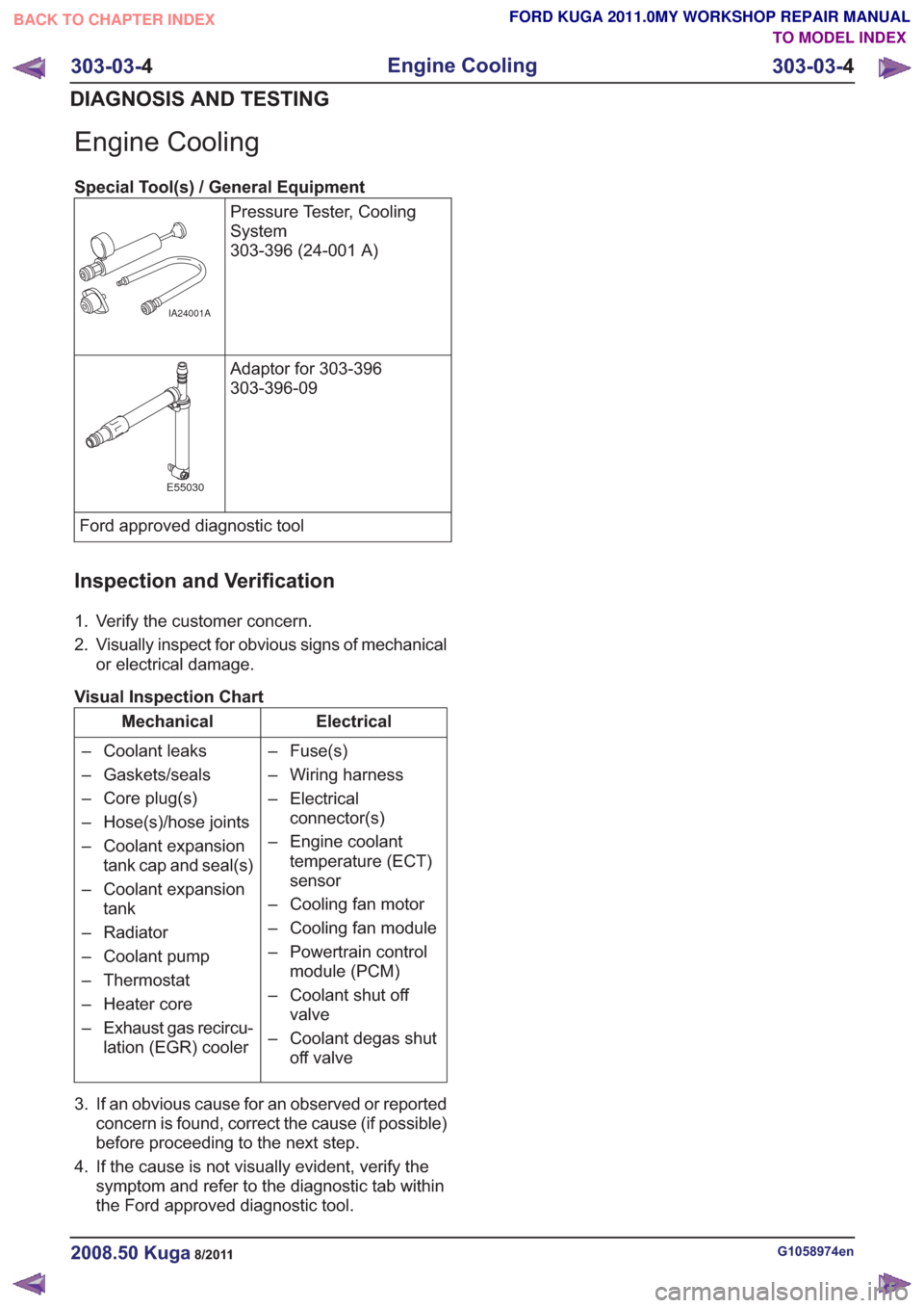
Engine Cooling
Special Tool(s) / General EquipmentPressure Tester, Cooling
System
303-396 (24-001 A)
IA24001A
Adaptor for 303-396
303-396-09
E55030
Ford approved diagnostic tool
Inspection and Verification
1. Verify the customer concern.
2. Visually inspect for obvious signs of mechanicalor electrical damage.
Visual Inspection Chart
Electrical
Mechanical
– Fuse(s)
– Wiring harness
– Electricalconnector(s)
– Engine coolant temperature (ECT)
sensor
– Cooling fan motor
– Cooling fan module
– Powertrain control module (PCM)
– Coolant shut off valve
– Coolant degas shut off valve
– Coolant leaks
– Gaskets/seals
– Core plug(s)
– Hose(s)/hose joints
– Coolant expansion
tank cap and seal(s)
– Coolant expansion tank
– Radiator
– Coolant pump
– Thermostat
– Heater core
– Exhaust gas recircu- lation (EGR) cooler
3. If an obvious cause for an observed or reported concern is found, correct the cause (if possible)
before proceeding to the next step.
4. If the cause is not visually evident, verify the symptom and refer to the diagnostic tab within
the Ford approved diagnostic tool.
G1058974en2008.50 Kuga8/2011
303-03- 4
Engine Cooling
303-03- 4
DIAGNOSIS AND TESTING
TO MODEL INDEX
BACK TO CHAPTER INDEX
FORD KUGA 2011.0MY WORKSHOP REPAIR MANUAL
Page 1695 of 2057
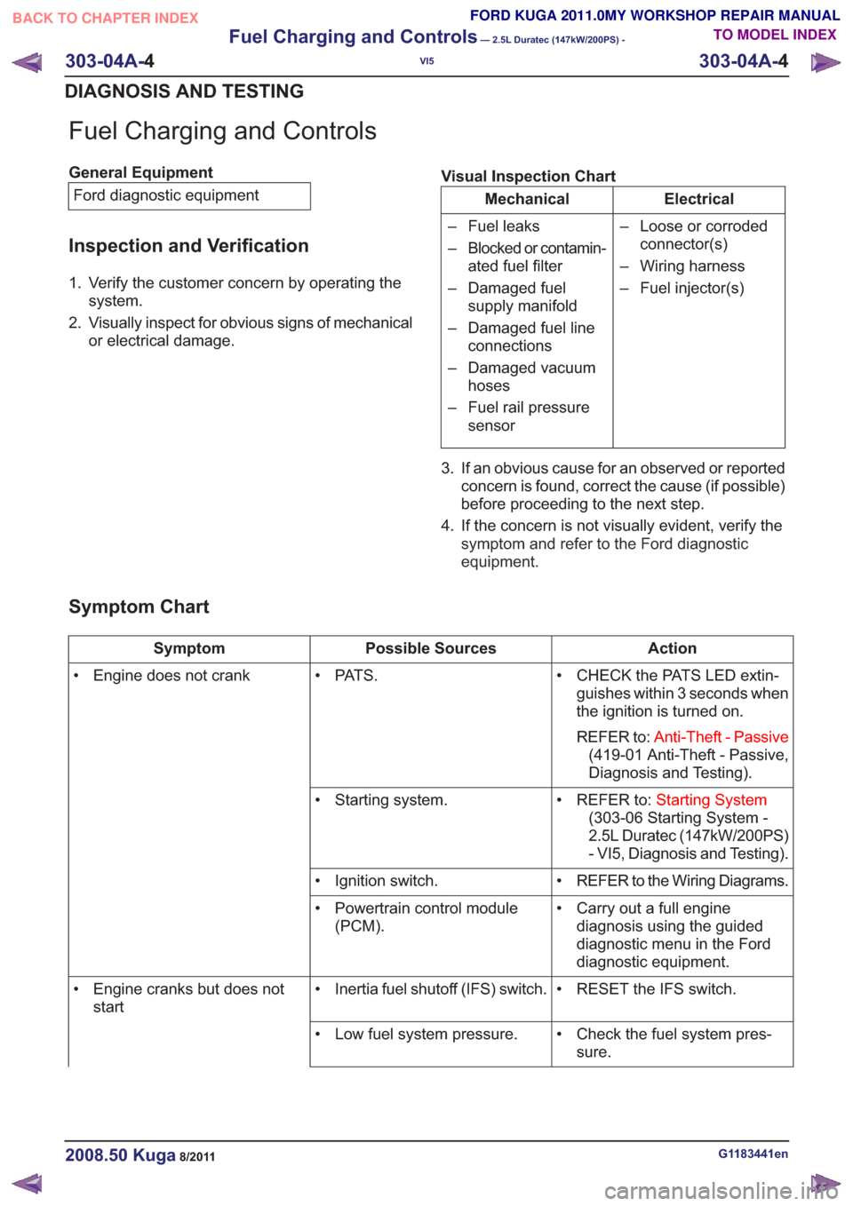
Fuel Charging and Controls
General EquipmentFord diagnostic equipment
Inspection and Verification
1. Verify the customer concern by operating the system.
2. Visually inspect for obvious signs of mechanical or electrical damage. Visual Inspection Chart
Electrical
Mechanical
– Loose or corrodedconnector(s)
– Wiring harness
– Fuel injector(s)
– Fuel leaks
– Blocked or contamin-
ated fuel filter
– Damaged fuel supply manifold
– Damaged fuel line connections
– Damaged vacuum hoses
– Fuel rail pressure sensor
3. If an obvious cause for an observed or reported concern is found, correct the cause (if possible)
before proceeding to the next step.
4. If the concern is not visually evident, verify the symptom and refer to the Ford diagnostic
equipment .
Symptom Chart
Action
Possible Sources
Symptom
• CHECK the PATS LED extin-guishes within 3 seconds when
the ignition is turned on.
REFER to: Anti-Theft - Passive
(419-01 Anti-Theft - Passive,
Diagnosis and Testing).
• PAT S .
• Engine does not crank
• REFER to:Starting System
(303-06 Starting System -
2.5L Duratec (147kW/200PS)
- VI5, Diagnosis and Testing).
• Starting system.
• REFER to the Wiring Diagrams.
• Ignition switch.
• Carry out a full enginediagnosis using the guided
diagnostic menu in the Ford
diagnostic equipment.
• Powertrain control module
(PCM).
• RESET the IFS switch.
• Inertia fuel shutoff (IFS) switch.
• Engine cranks but does not
start
• Check the fuel system pres-sure.
• Low fuel system pressure.
G1183441en2008.50 Kuga8/2011
303-04A-
4
Fuel Charging and Controls
— 2.5L Duratec (147kW/200PS) -
VI5
303-04A- 4
DIAGNOSIS AND TESTING
TO MODEL INDEX
BACK TO CHAPTER INDEX
FORD KUGA 2011.0MY WORKSHOP REPAIR MANUAL
Page 1696 of 2057
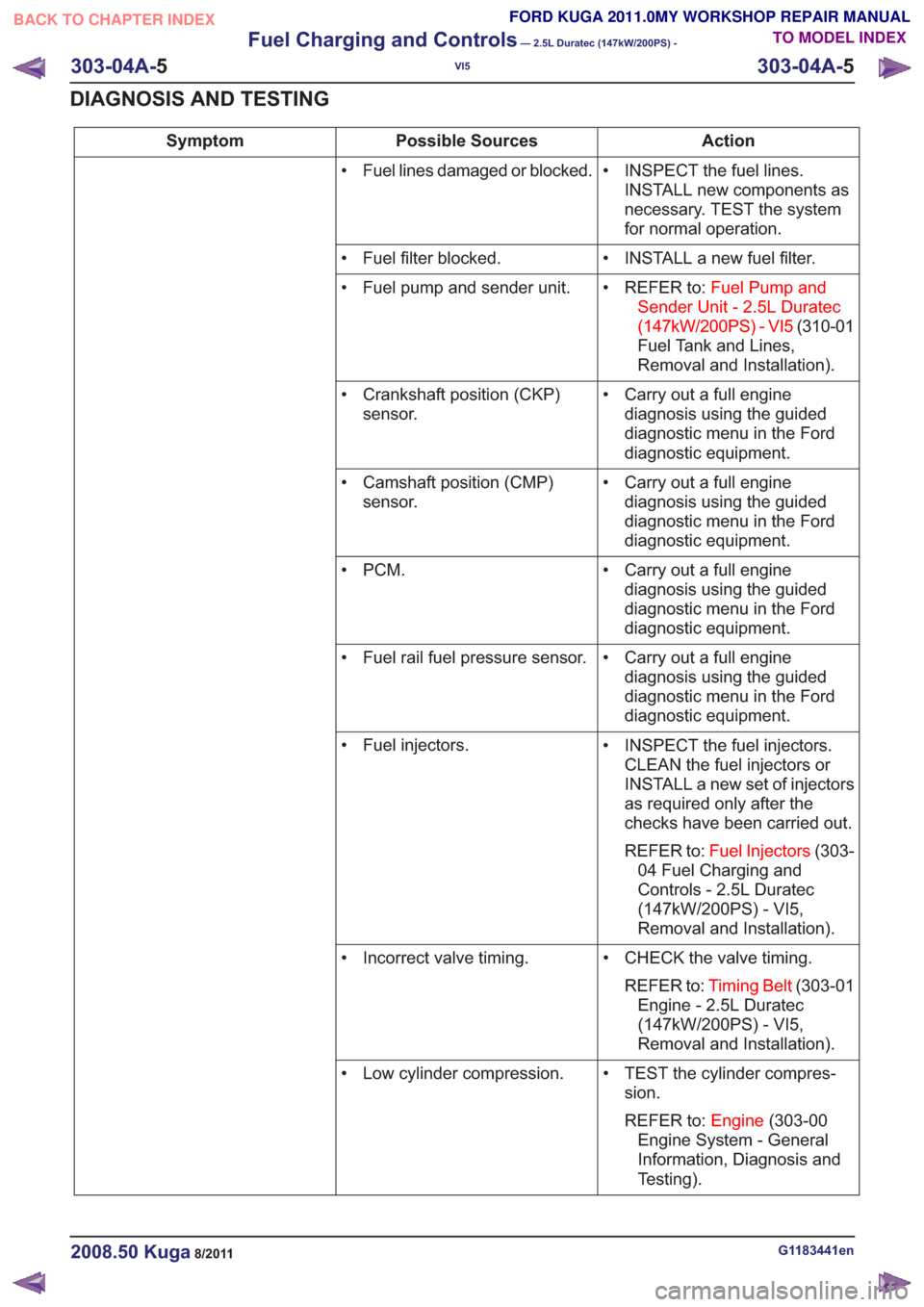
Action
Possible Sources
Symptom
• INSPECT the fuel lines.INSTALL new components as
necessary. TEST the system
for normal operation.
• Fuel lines damaged or blocked.
• INSTALL a new fuel filter.
• Fuel filter blocked.
• REFER to:Fuel Pump and
Sender Unit - 2.5L Duratec
(147kW/200PS) - VI5 (310-01
Fuel Tank and Lines,
Removal and Installation).
• Fuel pump and sender unit.
• Carry out a full enginediagnosis using the guided
diagnostic menu in the Ford
diagnostic equipment.
• Crankshaft position (CKP)
sensor.
• Carry out a full enginediagnosis using the guided
diagnostic menu in the Ford
diagnostic equipment.
• Camshaft position (CMP)
sensor.
• Carry out a full enginediagnosis using the guided
diagnostic menu in the Ford
diagnostic equipment.
•PCM.
• Carry out a full enginediagnosis using the guided
diagnostic menu in the Ford
diagnostic equipment.
• Fuel rail fuel pressure sensor.
• INSPECT the fuel injectors.CLEAN the fuel injectors or
INSTALL a new set of injectors
as required only after the
checks have been carried out.
REFER to: Fuel Injectors (303-
04 Fuel Charging and
Controls - 2.5L Duratec
(147kW/200PS) - VI5,
Removal and Installation).
• Fuel injectors.
• CHECK the valve timing.REFER to: Timing Belt (303-01
Engine - 2.5L Duratec
(147kW/200PS) - VI5,
Removal and Installation).
• Incorrect valve timing.
• TEST the cylinder compres-sion.
REFER to: Engine(303-00
Engine System - General
Information, Diagnosis and
Testing).
• Low cylinder compression.
G1183441en2008.50 Kuga8/2011
303-04A-
5
Fuel Charging and Controls
— 2.5L Duratec (147kW/200PS) -
VI5
303-04A- 5
DIAGNOSIS AND TESTING
TO MODEL INDEX
BACK TO CHAPTER INDEX
FORD KUGA 2011.0MY WORKSHOP REPAIR MANUAL