Page 1 of 655
To the best of our knowledge, the illustrations, technical information, data and descriptions in
this issue were correct at the time of going to print. The right to change prices, specifications,
equipment and maintenance instructions at any time without notice is reserved as part of FORD
policy of continuous development and improvement for the benefit of our customers.
No part of this publication may be reproduced, stored in a data processing system or transmitted
in any form, electronic, mechanical, photocopy, recording, translation or by any other means
withoutpriorpermissionofFord Motor Company.Noliabilitycanbeacceptedforany
inaccuracies in this publication, although every possible care has been taken to make it as
complete and accurate as possible.2011.0 Kuga
Copyright © FOREWORD
BACK TO FRONT PAGE
FORD KUGA 2011.0MY WIRING DIAGRAMS
VIEW MAIN INDEX
Page 10 of 655
Description
Sub-system Code
System Code
Fog lamps
D
L
Headlamps
E
L
Exterior lighting
F
L
Turn signal and hazard lamps
G
L
Instrument cluster and panel illumination
H
L
Instrument panel illumination
K
L
Communication, cellular phone, voice control
C
M
Information and entertainment
D
M
Ambulance
A
N
Police
B
N
Ta x i
C
N
Trailer tow
D
N
Engine cooling
A
P
Speed control
G
P
Connectors
A
R
Destination notes
B
R
Powertrain controller, diode, driver, monitor, pump
D
R
PCM (powertrain control module)
E
R
Motors
G
R
Relays
H
R
Sensors
J
R
Solenoids
L
R
Splices or busbars
N
R
Switches
P
R
Engine ignition
R
R
Powertrain controller, diode, driver, monitor, pump
S
R
Transmission/transaxle, differential, axle
A
T
Automatic transmission
C
T
Transmission/transaxle, differential, axle
D
T
Temporary functions for any sub-system
L
X
2011.0 Kuga 100-00-6
100-00- 6
General Information
100-00- 6
DESCRIPTION AND OPERATION
BACK TO CHAPTER INDEX TO MODEL INDEXFORD KUGA 2011.0MY WIRING DIAGRAMS
Page 25 of 655

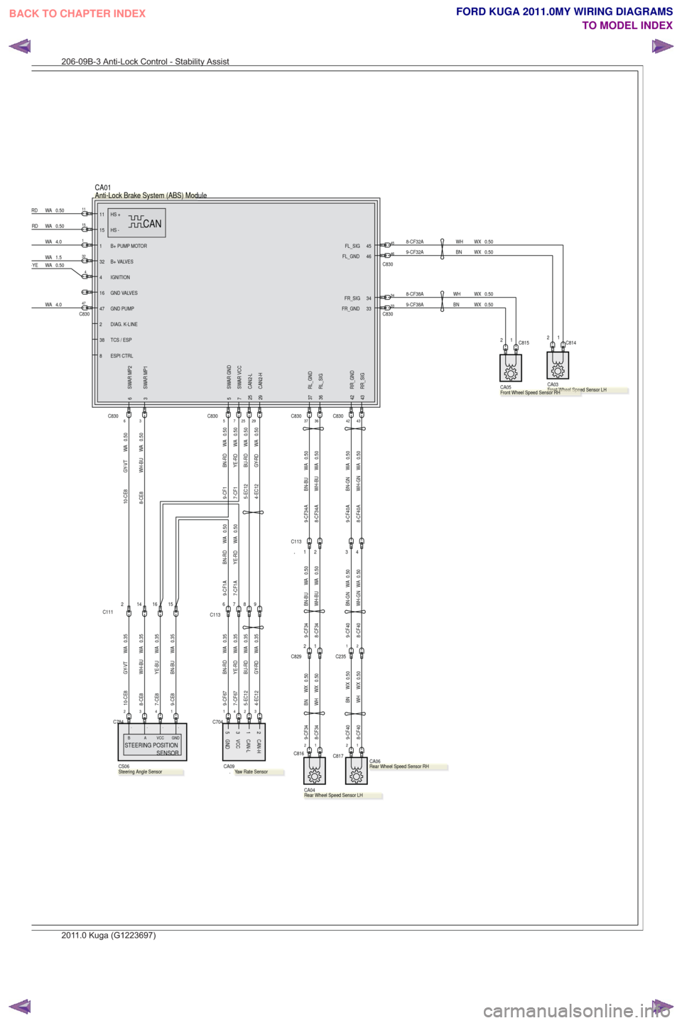
1 B+ PUMP MOTOR
34
FR_SIG
32 B+ VALVES
IGNITION
4
GND VALVES
16
FR_GND 33
45
FL_SIG46
FL_GND
36 RL_SIG
RL_GND
37
43 RR_SIG42 RR_GND
47 GND PUMP
CAN2-L
25CAN2-H
29
3 SWAR MP1
SWAR GND
5
6 SWAR MP27 SWAR VCC
TCS / ESP
38
ESPI CTRL
8
HS -15
HS +11
2 DIAG. K-LINE
CAN
CA01
4
1
32
474.0
WA
37C8303642C83043
4-EC12 GY-RD WA 0.355-EC12 BU-RD WA 0.359-CF67 BN-RD WA 0.357-CF67 YE-RD WA 0.35
C704
3241
44
GND53 VCCCAN-L1CAN-H2
.
CA09
0.50
WA
GY-RD
4-EC120.50
WA
BU-RD
5-EC12
2925
9-CE8 BN-BU WA 0.357-CE8 YE-BU WA 0.358-CE8 WH-BU WA 0.3510-CE8 GY-VT WA 0.35
0.50
WA
GY-VT
10-CE80.50
WA
WH-BU
8-CE8
3C8306
0.50
WA
BN-RD
9-CF1
7-CF1 YE-RD WA 0.50
7C8305
7-CF1A YE-RD WA 0.509-CF1A BN-RD WA 0.50
234
C784
1
784784
STEERING POSITION
SENSORVCC GNDA
B
CS06
.
....
15
C830
11
WA 4.0
WA 1.5
6
C113789
8-CF40A WH-GN WA 0.508-CF34A WH-BU WA 0.509-CF34A BN-BU WA 0.509-CF40A BN-GN WA 0.50
8-CF38A WH WX 0.509-CF38ABN WX 0.50
0.50WX
BN
9-CF32A0.50WX
WH
8-CF32A4546
C830
34
C83033
.
RD WA 0.50
RD WA 0.50
2
2
C817
1
.
CA06
4
1
C235
3
9-CF40 BN-GN WA 0.508-CF40 WH-GN WA 0.50
8-CF40
WH WX 0.509-CF40BN WX 0.501C8162
CA04
.
1
C1132
2
C8291
0.50
WA
BN-BU
9-CF340.50
WA
WH-BU
8-CF34
0.50WXBN
9-CF340.50WXWH
8-CF34
CA03
.
2 C81411
CA05.
2 C815
0.50
WA-YE
2
C111141615
Anti-Lock Brake System (ABS) Module
Yaw Rate Sensor.Steering Angle Sensor.Rear Wheel Speed Sensor RH
.Rear Wheel Speed Sensor LH
Front Wheel Speed Sensor LHeeeeeeFFFrontWheelSpeeFFFront..WheelSpeeFFFront..WheelSpee.rontWheelpSpeeFront Wheel Speed Sensor RH
206-09B-3 Anti-Lock Control - Stability Assist
2011.0 Kuga (G1223697)
BACK TO CHAPTER INDEX TO MODEL INDEXFORD KUGA 2011.0MY WIRING DIAGRAMS
Page 32 of 655
E7 RD WK 10.0
2
C793
C793
1
C794
1
10.0WK
BKE73
1
0.50
WA
BN-WH
9-CE10
0.50
WA
WH-VT
8-CE10
7-CE10 YE-VT WA 0.50
2
C792
A2 HS CAN -A3 HS CAN +
IGNITION
A1
B1 B+
B-B2
C15V +
S1 C3
GND C2
MOTOR EHPASM
CAN
CS05
.
3
1
C788
2GND
C1-2
POWER
C1-3
S1 (PWM) OUT
C1-1
CS06
1G
3G
2
C795 G
7-CE10 YE-VT WK 0.50
0.50WK
WH-VT
8-CE10
0.50WK
BN-WH
9-CE10
0.50
WA
GN-BUE7
GND
.Power Steering Control (PSC) ModuleSteering Angle Sensor
211-02-3 Power Steering—LHD 4WD/LHD FWD
2011.0 Kuga (G1223701)
BACK TO CHAPTER INDEX
TO MODEL INDEXFORD KUGA 2011.0MY WIRING DIAGRAMS
Page 34 of 655
E7 RD WK 10.0
2
C793
C793
1
C794
1
10.0WK
BKE7
A2 HS CAN -A3 HS CAN +
IGNITION
A1
B1 B+
B-B2
C15V +
S1 C3
GND C2
MOTOR EHPASM
CAN
CS05
.
GND
C1-2
POWER
C1-3
S1 (PWM) OUT
C1-1
CS06
1G
3G
2
C795 G
0.50
WA
BN-WH
9-CE10A
0.50
WA
WH-VT
8-CE10A
7-CE10A YE-VT WA 0.501
3
C792
2
0.50
WA
GN-BUE7
GND
.Power Steering Control (PSC) ModuleSteering Angle Sensor
211-02-5 Power Steering—RHD 4WD/RHD FWD
2011.0 Kuga (G1223702)
BACK TO CHAPTER INDEX
TO MODEL INDEXFORD KUGA 2011.0MY WIRING DIAGRAMS
Page 42 of 655
SECTION 303-03 Engine Cooling
VEHICLE APPLICATION:2011.0 Kuga
PA G E
CONTENTS
ELECTRICAL CONNECTORS
303-03-2
Cooling Fan Motor ........................................................................\
......................................
303-03-2
Cooling Fan Relay ........................................................................\
......................................
303-03-1
Engine Cooling
303-03- 1
.
BACK TO CHAPTER INDEX TO MODEL INDEXFORD KUGA 2011.0MY WIRING DIAGRAMS
Page 43 of 655
Cooling Fan Motor (G1239830)
4
1
2
3M5T-14A464-NCB
C281
TO COOLING FAN MODULE
HARNESS 14K733
49-PA6BUWA0.50
30-PA1BRDWA6.0
31-PA1BKWA6.0
Cooling Fan Relay (G1313031)
201
1.0 Kuga
303-03- 2
Engine Cooling
303-03-2
.
BACK TO CHAPTER INDEX TO MODEL INDEXFORD KUGA 2011.0MY WIRING DIAGRAMS
Page 59 of 655

SECTION 303-06A Starting System— 2.5L Duratec (147kW/200PS) - VI5
VEHICLE APPLICATION:2011.0 Kuga
PA G E
CONTENTS
ELECTRICAL SCHEMATICS
303-06A-2
Starting System — LHD 4WD ........................................................................\
....................
303-06A-4
Starting System — RHD 4WD ........................................................................\
....................
ELECTRICAL CONNECTORS 303-06A-6
Starter Motor ........................................................................\
...............................................
303-06A-6
Starter Motor ........................................................................\
...............................................
303-06A-6
Starter Relay ........................................................................\
...............................................
303-06A-1
Starting System— 2.5L Duratec (147kW/200PS) - VI5303-06A-
1
.
BACK TO CHAPTER INDEX TO MODEL INDEXFORD KUGA 2011.0MY WIRING DIAGRAMS