Page 2 of 655

2011.0 Kuga
Wiring Diagrams
Table of Contents
GROUP 1 General Information
Service InformationGeneral Information 100-00
GROUP 2 Chassis
Brake System
Parking Brake and Actuation 206-05
Hydraulic Brake Actuation 206-06
Power Brake Actuation 206-07
Anti-Lock Control 206-09A
Anti-Lock Control - Stability Assist 206-09B
Anti-Lock Brake System (ABS) and Stability Control 206-09C
Steering System Power Steering 211-02
Steering Column Switches 211-05
GROUP 3 Powertrain
Engine
Engine Cooling 303-03
Fuel Charging and Controls - 2.5L Duratec (147kW/200PS) -
VI5 303-04A
Fuel Charging and Controls - Turbocharger - 2.5L Duratec
(147kW/200PS) - VI5 303-04B
Fuel Charging and Controls - 2.0L Duratorq-TDCi (100kW/136PS) - DW,
Emission Requirements: Stage
IV 303-04C
Fuel Charging and Controls - 2.0L Duratorq-TDCi (100kW/136PS) -
DW/2.0L Duratorq-TDCi
(103kW/140PS) - DW/2.0L Duratorq-TDCi (120kW/163PS) - DW,
Emission Requirements: Stage
V
303-04D
Fuel Charging and Controls - Turbocharger - 2.0L Duratorq-TDCi
(100kW/136PS) - DW, Emission
Requirements: Stage IV 303-04E
Fuel Charging and Controls - Turbocharger - 2.0L Duratorq-TDCi
(100kW/136PS) - DW/2.0L
Duratorq-TDCi (103kW/140PS) -
DW/2.0L Duratorq-TDCi
(120kW/163PS) - DW, Emission
Requirements: Stage V 303-04F
Starting System - 2.5L Duratec (147kW/200PS) - VI5 303-06A
Starting System - 2.0L Duratorq-TDCi (100kW/136PS) - DW, Emission
Requirements: Stage IV 303-06B
Starting System - 2.0L Duratorq-TDCi (100kW/136PS) - DW/2.0L
Duratorq-TDCi (103kW/140PS) -
DW/2.0L Duratorq-TDCi
(120kW/163PS) - DW, Emission
Requirements: Stage V 303-06C
Engine Ignition - 2.5L Duratec (147kW/200PS) - VI5 303-07A
Glow Plug System - 2.0L Duratorq-TDCi (100kW/136PS) - DW, Emission
Requirements: Stage IV 303-07B
Engine Emission Control - 2.5L Duratec (147kW/200PS) - VI5 303-08A
Engine Emission Control - 2.0L Duratorq-TDCi (100kW/136PS) - DW,
Emission Requirements: Stage IV,
2.0L Duratorq-TDCi (DW)
Diesel 303-08B
Evaporative Emissions 303-13
Electronic Engine Controls - 2.5L Duratec (147kW/200PS) -
VI5 303-14A
201
1.0 Kuga
TO MODEL INDEX
BACK TO FOREWORD & FRONT PAGE
PAGE 1 OF 2
Page 6 of 655

About This Manual
How to Use This Manual
This manual is structured into Systems, Groups
and Sections. A System covers a specific portion
of the vehicle. The manual is divided into six
Systems: General Information, Chassis,
Powertrain, Electrical, Body and Paint and General
Wiring Information. Each System contains a
number of Groups that contain a number ofSections relating to specific vehicle systems. Each
Section contains a wiring diagram containing all of
the information relating to the specific vehicle
system. Some Sections contain a number of wiring
diagrams that cover a number of different vehicle
variants. Connector location information and
connector face views are provided through links
within the wiring diagram for each vehicle system.
Example:
Chassis > Brake System > Anti-Lock
Control (System > Group > Section)
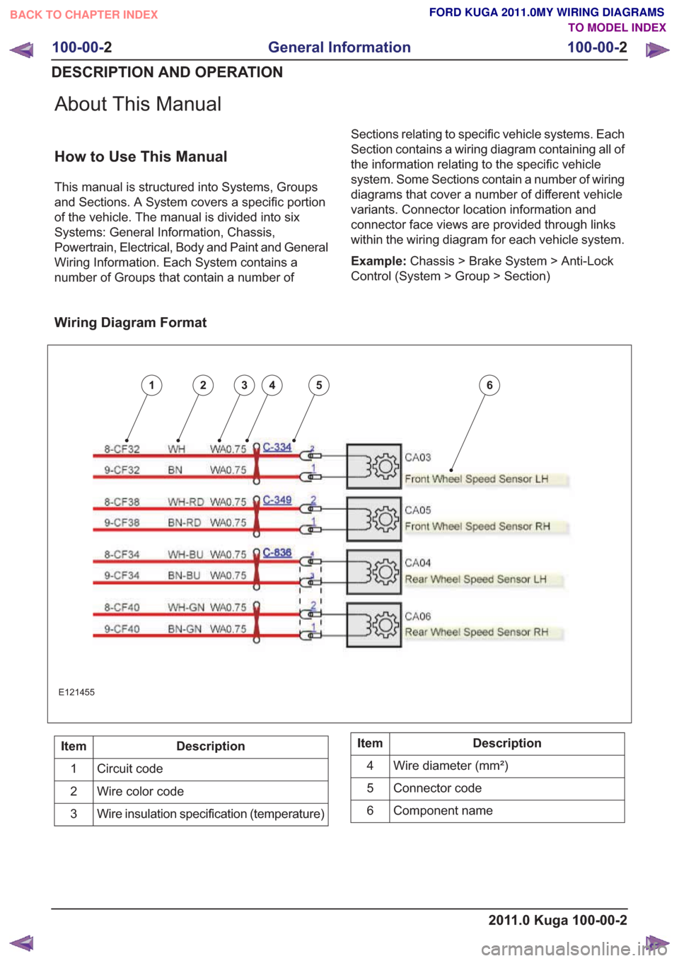
Wiring Diagram Format
123456
E121455
Description
Item
Circuit code
1
Wire color code
2
Wire insulation specification (temperature)
3Description
Item
Wire diameter (mm²)
4
Connector code
5
Component name
6
2011.0 Kuga 100-00-2
100-00- 2
General Information
100-00- 2
DESCRIPTION AND OPERATION
BACK TO CHAPTER INDEX TO MODEL INDEXFORD KUGA 2011.0MY WIRING DIAGRAMS
Page 8 of 655

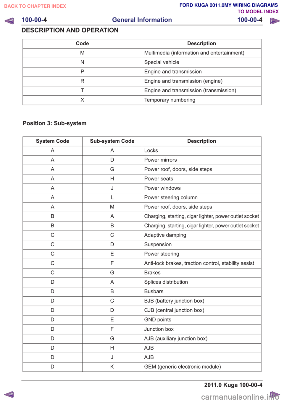
Description
Code
Multimedia (information and entertainment)
M
Special vehicle
N
Engine and transmission
P
Engine and transmission (engine)
R
Engine and transmission (transmission)
T
Temporary numbering
X
Position 3: Sub-system
Description
Sub-system Code
System Code
Locks
A
A
Power mirrors
D
A
Power roof, doors, side steps
G
A
Power seats
H
A
Power windows
J
A
Power steering column
L
A
Power roof, doors, side steps
M
A
Charging, starting, cigar lighter, power outlet socket
A
B
Charging, starting, cigar lighter, power outlet socket
B
B
Adaptive damping
C
C
Suspension
D
C
Power steering
E
C
Anti-lock brakes, traction control, stability assist
F
C
Brakes
G
C
Splices distribution
A
D
Busbars
B
D
BJB (battery junction box)
C
D
CJB (central junction box)
D
D
GND points
E
D
Junction box
F
D
AJB (auxiliary junction box)
G
D
AJB
H
D
AJB
J
D
GEM (generic electronic module)
K
D
2011.0 Kuga 100-00-4
100-00- 4
General Information
100-00- 4
DESCRIPTION AND OPERATION
BACK TO CHAPTER INDEX TO MODEL INDEXFORD KUGA 2011.0MY WIRING DIAGRAMS
Page 13 of 655

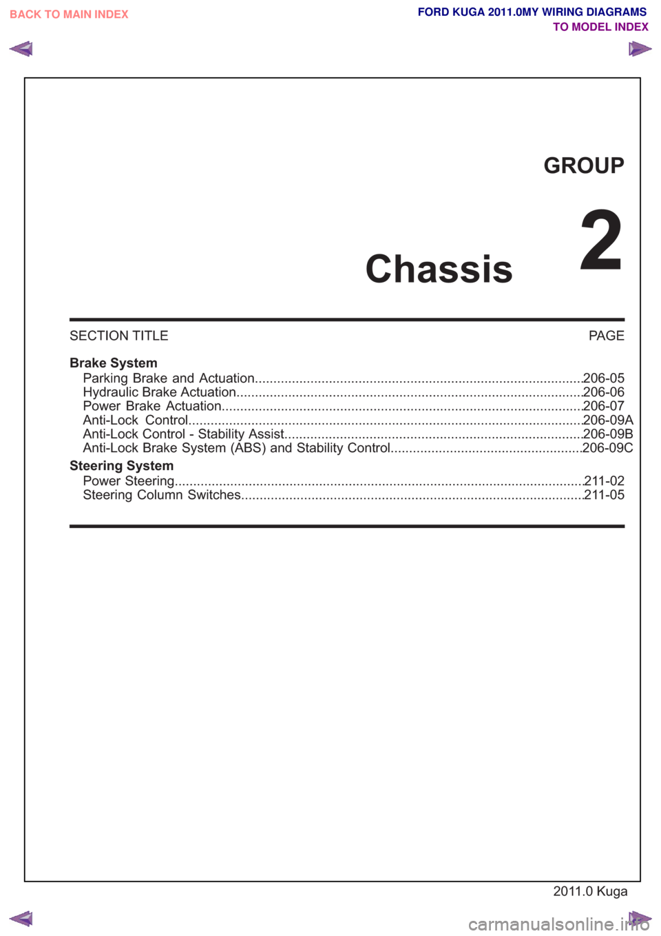
GROUP
Chassis
2
SECTION TITLEPAGE
Brake System Parking Brake and Actuation...............................................................\
..........................206-05
Hydraulic Brake Actuation...............................................................\
...............................206-06
Power Brake Actuation...............................................................\
...................................206-07
Anti-Lock Control.................................................................\
..........................................206- 09A
Anti-Lock Control - Stability Assist..................................................................\
...............206-09B
Anti-Lock Brake System (ABS) and Stability Control....................................................206-09C
Steering System Power Steering................................................................\
...............................................211 -02
Steering Column Switches................................................................\
.............................211-05
2011.0 Kuga
BACK TO MAIN INDEX
TO MODEL INDEXFORD KUGA 2011.0MY WIRING DIAGRAMS
Page 14 of 655
SECTION 206-05 Parking Brake and Actuation
VEHICLE APPLICATION:2011.0 Kuga
PA G E
CONTENTS
ELECTRICAL CONNECTORS
206-05-2
Parking Brake Switch ........................................................................\
..................................
206-05-2
Parking Brake Switch ........................................................................\
..................................
206-05-1
Parking Brake and Actuation
206-05- 1
.
BACK TO CHAPTER INDEX TO MODEL INDEXFORD KUGA 2011.0MY WIRING DIAGRAMS
Page 15 of 655
Parking Brake Switch (G1240673)
Parking Brake Switch (G1226596)
12
4S7T-14489-VAA
C931
TO Z-HANDBRAKE SWITCH
HARNESS 14014 PIN 1 => 31S-GE44C BK-RD 0.75 WA
31S-GE44ABK-RDWA0.75
201
1.0 Kuga
206-05- 2
Parking Brake and Actuation
206-05-2
.
BACK TO CHAPTER INDEX TO MODEL INDEXFORD KUGA 2011.0MY WIRING DIAGRAMS
Page 16 of 655
SECTION 206-06 Hydraulic Brake Actuation
VEHICLE APPLICATION:2011.0 Kuga
PA G E
CONTENTS
ELECTRICAL CONNECTORS
206-06-2
Low Brake Fluid Warning Indicator Switch ........................................................................\
.
206-06-1
Hydraulic Brake Actuation
206-06- 1
.
BACK TO CHAPTER INDEX TO MODEL INDEXFORD KUGA 2011.0MY WIRING DIAGRAMS
Page 17 of 655
Low Brake Fluid Warning Indicator Switch (G1226597)
12
XR3T-14A464-AA
C810
TO BRAKE FLUID LEVEL SWITCH
HARNESS 14K733 PIN 1 => 91-GC7B BK-BU 1.0 WA
PIN 1 => 91-GC7A BK-BU 1.0 WA
91-GC7BK-BUWA0.50
31S-GC6BK-YEWA0.50
201
1.0 Kuga
206-06- 2
Hydraulic Brake Actuation
206-06-2
.
BACK TO CHAPTER INDEX TO MODEL INDEXFORD KUGA 2011.0MY WIRING DIAGRAMS