Page 312 of 461

The ELD is designed for off-road use only and is not intended for use on
dry pavement.
Activating the electronic locking differential (ELD)
The ELD can be turned on by
pulling the knob on the 4WD control
toward you while the control is in
either 4H (4X4 high) or 4L (4X4
low) mode.
Once the knob is pulled, the
light located on the control will
blink for approximately two seconds
and then it will remain solid. The
indicator light will also display in
the message center.
Once the
light on the control
remains solid and the
indicator
light is displayed in the message
center, both rear wheel axle shafts
will be locked together providing
added traction.
If the
light blinks for 10 seconds, then turns off, and theindicator
light in the message center turns off, one of the following has occurred:
•The vehicle speed is too high.
•The left and right rear wheel speed difference is too high during an
engagement attempt.
•The system has malfunctioned and will be accompanied by aCHECK
LOCKING DIFFERENTIALmessage in the message center.
Note:If the ELD has difficulty disengaging, release the accelerator pedal
and turn the steering wheel in the opposite direction while rolling.
Driving off-road with truck and utility vehicles
4WD vehicles are specially equipped for driving on sand, snow, mud and
rough terrain and have operating characteristics that are somewhat
different from conventional vehicles, both on and off the road.
Your vehicle may be equipped with a front air dam that can become
damaged (due to reduced ground clearance) when taking your vehicle
off-road. This air dam can be taken off by removing two bolts.
Driving
312
2011 F-150(f12)
Owners Guide, 1st Printing
USA(fus)
Page 321 of 461

ROADSIDE ASSISTANCE
Getting roadside assistance
To fully assist you should you have a vehicle concern, Ford Motor
Company offers a complimentary roadside assistance program. This
program is separate from the New Vehicle Limited Warranty. The service
is available:
•24-hours, seven days a week
•for the coverage period listed on the Roadside Assistance Card
included in your Owner Guide portfolio.
Roadside assistance will cover:
•a flat tire change with a good spare (except vehicles that have been
supplied with a tire inflation kit)
•battery jump start
•lock-out assistance (key replacement cost is the customer’s
responsibility)
•fuel delivery – Independent Service Contractors, if not prohibited by
state, local or municipal law shall deliver up to 2.0 gallons (7.5L) of
gasoline or 5.0 gallons (18.9L) of diesel fuel to a disabled vehicle. Fuel
delivery service is limited to two no-charge occurrences within a
12-month period.
•winch out – available within 100 feet (30.5 meters) of a paved or
county maintained road, no recoveries.
•towing – Ford and Lincoln eligible vehicles towed to an authorized
dealer within 35 miles (56 km) of the disablement location or to the
nearest authorized dealer. If a member requests to be towed to an
authorized dealer more than 35 miles (56 km) from the disablement
location, the member shall be responsible for any mileage costs in
excess of 35 miles (56 km).
Trailers shall be covered up to $200 if the disabled eligible vehicle
requires service at the nearest authorized dealer. If the trailer is disabled,
but the towing vehicle is operational, the trailer does not qualify for any
roadside services.
Roadside Emergencies
321
2011 F-150(f12)
Owners Guide, 1st Printing
USA(fus)
Page 322 of 461

Canadian customers refer to your Warranty Guide or visit our
website at www.ford.ca for information on:
Using roadside assistance
Complete the roadside assistance identification card and place it in your
wallet for quick reference. In the United States, this card is found in the
Owner Guide portfolio in the glove compartment. In Canada, the card is
found in theWarranty Guidein the glove compartment.
U.S. Ford and Lincoln vehicle customers who require Roadside
Assistance, call 1-800-241-3673.
Canadian customers who require roadside assistance, call
1-800-665-2006.
If you need to arrange roadside assistance for yourself, Ford Motor
Company will reimburse a reasonable amount for towing to the nearest
dealership within 35 miles (56 km). To obtain reimbursement
information, U.S. Ford and Lincoln vehicle customers call
1-800-241-3673. Customers will be asked to submit their original
receipts.
Canadian customers who need to obtain reimbursement information, call
1-800-665-2006 or visit our website at www.ford.ca.
HAZARD FLASHER CONTROL
The hazard flasher control is located
on the instrument panel by the
radio. The hazard flashers will
operate when the ignition is in any
position or if the key is not in the
ignition.
•Press the flasher control and all front and rear direction signals will
flash.
•Press the flasher control again to turn them off.
Use it when your vehicle is disabled and is creating a safety hazard for
other motorists.
Note:With extended use, the flasher may run down your battery.
Roadside Emergencies
322
2011 F-150(f12)
Owners Guide, 1st Printing
USA(fus)
Page 324 of 461

Standard fuse amperage rating and color
COLOR
Fuse
ratingMini
fusesStandard
fusesMaxi
fusesCartridge
maxi
fusesFuse link
cartridge
2A Grey Grey — — —
3A Violet Violet — — —
4A Pink Pink — — —
5A Tan Tan — — —
7.5A Brown Brown — — —
10A Red Red — — —
15A Blue Blue — — —
20A Yellow Yellow Yellow Blue Blue
25A Natural Natural — Natural Natural
30A Green Green Green Pink Pink
40A — — Orange Green Green
50A — — Red Red Red
60A — — Blue Yellow Yellow
70A — — Tan — Brown
80A — — Natural Black Black
Passenger compartment fuse panel
The fuse panel is located under the right-hand side of the instrument
panel.
To remove the trim panel for access
to the fuse box, pull the panel
toward you and swing it out away
from the side and remove it. To
reinstall it, line up the tabs with the
grooves on the panel, then push it
shut.
To remove the fuse box cover, press in the tabs on both sides of the
cover, then pull the cover off.
Roadside Emergencies
324
2011 F-150(f12)
Owners Guide, 1st Printing
USA(fus)
Page 328 of 461
If the battery has been disconnected and reconnected, refer to the
Batterysection of theMaintenance and Specificationschapter.
The high-current fuses are coded as follows:
Fuse/Relay
LocationFuse Amp
RatingProtected Circuits
1 — Powertrain control module (PCM)
relay (3.7L, 5.0L and 6.2L engines)
2 — Starter relay
3 — Blower motor relay
4 — Rear window defroster relay
5 — Electric fan relay (high speed)
6 — Trailer tow (TT) park lamp relay
7 — Run/start relay
8 — Fuel pump relay
9 — TT Battery charger relay
10 — PCM relay (3.5L engine)
11 30A** Power running board motors
1240A** Electric fan
50A** Electric fan (6.2L with max trailer
tow, SVT Raptor)
13 30A** Starter relay power
Roadside Emergencies
328
2011 F-150(f12)
Owners Guide, 1st Printing
USA(fus)
Page 329 of 461

Fuse/Relay
LocationFuse Amp
RatingProtected Circuits
14 30A** Passenger power seat
1540A** Electric fan
50A** Electric fan (6.2L with max trailer
tow, SVT Raptor)
16 — Not used
17 30A** Trailer brake control
18 30A** Upfitter 1 (SVT Raptor)
19 30A** Upfitter 2 (SVT Raptor)
20 20A** 4x4 module (electronic shift)
21 30A** TT battery charge relay power
22 20A** Cigar lighter
23 — A/C clutch relay
24 — Not used
25 — Vacuum pump relay (3.5L engine)
26 10A* PCM – keep alive power, PCM relay
coil, canister vent solenoid (3.7L,
5.0L and 6.2L engines)
27 20A* Fuel pump relay power
28 10A* Upfitter 4 (SVT Raptor)
29 10A* 4x4 IWE solenoid
30 10A* A/C clutch
31 15A* Run/start relay power
32 40A** Rear window defroster relay power
33 40A** 110V AC power point
34 40A** PCM relay power (3.7L, 5.0L and
6.2L engines)
50A** PCM relay power (3.5L engine)
35 — Not used
36 30A** Roll stability control (RSC)/Anti-lock
brake system (ABS)
37 — TT left stop/turn relay
38 — TT right stop/turn relay
Roadside Emergencies
329
2011 F-150(f12)
Owners Guide, 1st Printing
USA(fus)
Page 334 of 461

When driving with one of the dissimilar spare tires listed above,do not:
•Exceed 50 mph (80 km/h)
•Load the vehicle beyond maximum vehicle load rating listed on the
Safety Compliance Label
•Tow a trailer
•Use snow chains on the end of the vehicle with the dissimilar spare
tire
•Use more than one dissimilar spare tire at a time
•Use commercial car washing equipment
•Try to repair the dissimilar spare tire
Use of one of the dissimilar spare tires listed above at any one wheel
location can lead to impairment of the following:
•Handling, stability and braking performance
•Comfort and noise
•Ground clearance and parking at curbs
•Winter weather driving capability
•Wet weather driving capability
•All-wheel driving capability (if applicable)
3.Full-size dissimilar spare without label on wheel
When driving with the full-size dissimilar spare tire/wheel,do not:
•Exceed 70 mph (113 km/h)
•Use more than one dissimilar spare tire/wheel at a time
•Use commercial car washing equipment
•Use snow chains on the end of the vehicle with the dissimilar spare
tire/wheel
The usage of a full-size dissimilar spare tire/wheel can lead to
impairment of the following:
•Handling, stability and braking performance
•Comfort and noise
•Ground clearance and parking at curbs
•Winter weather driving capability
•Wet weather driving capability
•All-wheel driving capability (if applicable)
Roadside Emergencies
334
2011 F-150(f12)
Owners Guide, 1st Printing
USA(fus)
Page 335 of 461

•Load leveling adjustment (if applicable)
When driving with the full-size dissimilar spare tire/wheel additional
caution should be given to:
•Towing a trailer
•Driving vehicles equipped with a camper body
•Driving vehicles with a load on the cargo rack
Drive cautiously when using a full-size dissimilar spare tire/wheel and
seek service as soon as possible.
Stopping and securing the vehicle
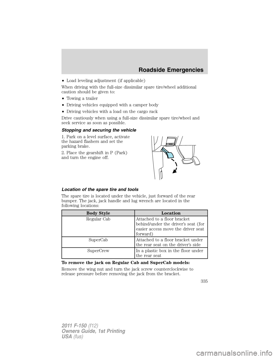
1. Park on a level surface, activate
the hazard flashers and set the
parking brake.
2. Place the gearshift in P (Park)
and turn the engine off.
Location of the spare tire and tools
The spare tire is located under the vehicle, just forward of the rear
bumper. The jack, jack handle and lug wrench are located in the
following locations:
Body Style Location
Regular Cab Attached to a floor bracket
behind/under the driver’s seat (for
easier access move the driver seat
forward)
SuperCab Attached to a floor bracket under
the rear seat on the driver’s side
SuperCrew In a plastic box in the floor under
the rear seat
To remove the jack on Regular Cab and SuperCab models:
Remove the wing nut and turn the jack screw counterclockwise to
release pressure before removing the jack from the bracket.
Roadside Emergencies
335
2011 F-150(f12)
Owners Guide, 1st Printing
USA(fus)