Page 71 of 339

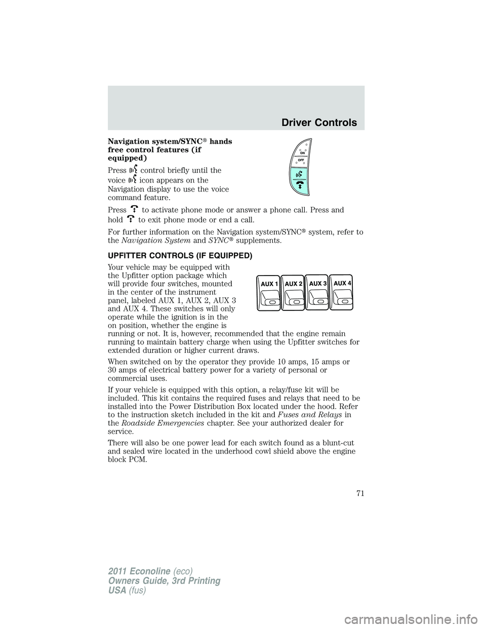
Navigation system/SYNC�hands
free control features (if
equipped)
Press
control briefly until the
voice
icon appears on the
Navigation display to use the voice
command feature.
Press
to activate phone mode or answer a phone call. Press and
hold
to exit phone mode or end a call.
For further information on the Navigation system/SYNC�system, refer to
theNavigation SystemandSYNC�supplements.
UPFITTER CONTROLS (IF EQUIPPED)
Your vehicle may be equipped with
the Upfitter option package which
will provide four switches, mounted
in the center of the instrument
panel, labeled AUX 1, AUX 2, AUX 3
and AUX 4. These switches will only
operate while the ignition is in the
on position, whether the engine is
running or not. It is, however, recommended that the engine remain
running to maintain battery charge when using the Upfitter switches for
extended duration or higher current draws.
When switched on by the operator they provide 10 amps, 15 amps or
30 amps of electrical battery power for a variety of personal or
commercial uses.
If your vehicle is equipped with this option, a relay/fuse kit will be
included. This kit contains the required fuses and relays that need to be
installed into the Power Distribution Box located under the hood. Refer
to the instruction sketch included in the kit andFuses and Relaysin
theRoadside Emergencieschapter. See your authorized dealer for
service.
There will also be one power lead for each switch found as a blunt-cut
and sealed wire located in the underhood cowl shield above the engine
block PCM.
Driver Controls
71
2011 Econoline(eco)
Owners Guide, 3rd Printing
USA(fus)
Page 72 of 339
They are coded as follows:
Switch Circuit number Wire color Fuse
AUX 1 CAC05 Yellow 30A
AUX 2 CAC06 Green with
Brown Trace30A
AUX 3 CAC07 Violet with
Green Trace10A
AUX 4 CAC08 Brown 15A
More detailed information about Upfitter switches can be found at
https://www.fleet.ford.com/truckbbas/.
POSITIVE RETENTION FLOOR MAT (IF EQUIPPED)
WARNING:Do not install additional floor mats on top of the
factory installed floor mats as they may interfere with the
accelerator or the brake pedals.
Position the floor mat so that the
eyelets are over the retention posts
and press down to lock in. Make
sure that the mat does not interfere
with the operation of the accelerator
or the brake pedal. To remove the
floor mat, reverse the installation
procedure.
Driver Controls
72
2011 Econoline(eco)
Owners Guide, 3rd Printing
USA(fus)
Page 214 of 339

VEHICLE USED AS A STATIONARY POWER SOURCE
Auxiliary equipment called power take-off or PTO, is often added to the
engine or transmission to operate utility equipment. Examples include a
wheel-lift for tow trucks, cranes, tools for construction or tire service and
pumping fluids. PTO applications draw auxiliary horsepower from the
powertrain, often while the vehicle is stationary. In this condition, there
is limited cooling air flow through the radiator and around the vehicle
that normally occurs when a vehicle is moving. The aftermarket PTO
system installer, having the most knowledge of the final application, is
responsible for determining whether additional chassis heat protection or
powertrain cooling is required, and alerting the user to the safe and
proper operation.
Your vehicle is qualified for use as a stationary power source, within
limits detailed in theFord Truck Body Builders Layout Book,found at
www.fleet.ford.com/truckbbas, and through the Ford Truck Body Builders
Advisory Service.
Gas engine vehicles are qualified for up to 10 minutes of continuous
operation as a stationary power source, due to the potential for the
normal venting of fuel vapors. Further consult your aftermarket PTO
installer, since the duration of operation limit for the aftermarket PTO
may be less than the vehicle is capable of.
DRIVING THROUGH WATER
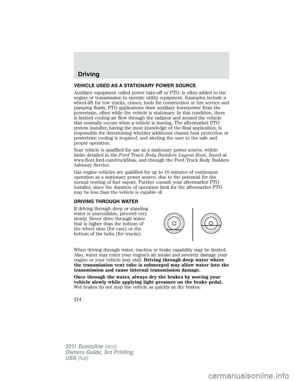
If driving through deep or standing
water is unavoidable, proceed very
slowly. Never drive through water
that is higher than the bottom of
the wheel rims (for cars) or the
bottom of the hubs (for trucks).
When driving through water, traction or brake capability may be limited.
Also, water may enter your engine’s air intake and severely damage your
engine or your vehicle may stall.Driving through deep water where
the transmission vent tube is submerged may allow water into the
transmission and cause internal transmission damage.
Once through the water, always dry the brakes by moving your
vehicle slowly while applying light pressure on the brake pedal.
Wet brakes do not stop the vehicle as quickly as dry brakes.
Driving
214
2011 Econoline(eco)
Owners Guide, 3rd Printing
USA(fus)
Page 219 of 339

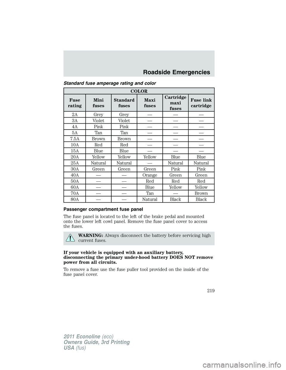
Standard fuse amperage rating and color
COLOR
Fuse
ratingMini
fusesStandard
fusesMaxi
fusesCartridge
maxi
fusesFuse link
cartridge
2A Grey Grey — — —
3A Violet Violet — — —
4A Pink Pink — — —
5A Tan Tan — — —
7.5A Brown Brown — — —
10A Red Red — — —
15A Blue Blue — — —
20A Yellow Yellow Yellow Blue Blue
25A Natural Natural — Natural Natural
30A Green Green Green Pink Pink
40A — — Orange Green Green
50A — — Red Red Red
60A — — Blue Yellow Yellow
70A — — Tan — Brown
80A — — Natural Black Black
Passenger compartment fuse panel
The fuse panel is located to the left of the brake pedal and mounted
onto the lower left cowl panel. Remove the fuse panel cover to access
the fuses.
WARNING:Always disconnect the battery before servicing high
current fuses.
If your vehicle is equipped with an auxiliary battery,
disconnecting the primary under-hood battery DOES NOT remove
power from all circuits.
To remove a fuse use the fuse puller tool provided on the inside of the
fuse panel cover.
Roadside Emergencies
219
2011 Econoline(eco)
Owners Guide, 3rd Printing
USA(fus)
Page 222 of 339

Fuse/Relay
LocationFuse Amp
RatingProtected Circuits
40 20A Amplifier
41 15A Radio, Switch illumination,
Reverse camera mirror, Automatic
dimming rear view mirror
42 10A Upfitter switch
43 10A Stripped chassis IP connector #1
44 10A Auxiliary battery relay/Trailer tow
battery charger relay
45 5A Wipers, Stripped chassis Engine
connector 3
46 7.5A Passenger airbag deactivation
indicator (PADI)
47 30A circuit
breakerWindows accessory delay
48 Relay Delayed accessory
Power distribution box
The power distribution box is located in the engine compartment. The
power distribution box contains high-current fuses that protect your
vehicle’s main electrical systems from overloads.
WARNING:Always disconnect the battery before servicing high
current fuses.
WARNING:To reduce risk of electrical shock, always replace
the cover to the Power Distribution Box before reconnecting the
battery or refilling fluid reservoirs.
If your vehicle is equipped with an auxiliary battery,
disconnecting the primary under-hood battery DOES NOT remove
power from all circuits.
If the battery has been disconnected and reconnected, refer to the
Batterysection of theMaintenance and Specificationschapter.
Roadside Emergencies
222
2011 Econoline(eco)
Owners Guide, 3rd Printing
USA(fus)
Page 223 of 339
The high-current fuses are coded as follows.
Fuse/Relay
LocationFuse Amp
RatingProtected Circuits
1 HC Micro Relay Powertrain control module (PCM)
2 HC Micro Relay Starter solenoid
3 HC Micro Relay Wiper
4 HC Micro Relay Trailer tow battery charge
5 HC Micro Relay Fuel pump
6 HC Micro Relay Trailer tow park lamp
7 HC Micro Relay Upfitter #4
8 HC Micro Relay Upfitter #3
9 HC Micro Relay Modified vehicle and stripped
chassis run/start
10 — Not used
11 — Not used
12 40A** Modified vehicle and stripped
chassis run/start
13 30A** Starter solenoid relay
14 40A** Run start relay
15 40A** Modified vehicle and stripped
chassis battery
16 50A** Auxiliary A/C blower
Roadside Emergencies
223
2011 Econoline(eco)
Owners Guide, 3rd Printing
USA(fus)
Page 225 of 339
Fuse/Relay
LocationFuse Amp
RatingProtected Circuits
44 10A* Upfitter #3
45 15A* Upfitter #4
46 10A* PCM keep alive power, Canister
vent, PCM relay coil
47 40A** ABS coil
48 20A** Trailer tow stop lamp/turn signal
49 30A** Wiper motor
50 — Not used
51 20A** Cutaway
52 10A* Stripped chassis and modified
vehicle run/start relay coil
53 10A* ABS run/start feed
54 10A* Fuel pump relay coil
55 — Not used
56 — Not used
57 20A* Trailer tow park lamp
58 15A* Trailer tow backup lamp
59 — Not used
60 — One touch integrated start (OTIS)
(diode)
61 — Auxiliary battery (diode)
62 HC Micro relay Upfitter #2
63 30A** Trailer tow battery charge
64 — Not used
65 20A** Power point 2 (glove box)
66 20A** Power point 3 (left-hand B-pillar)
67 20A** Power point 1 (instrument panel)
68 50A** Modified vehicle
69 — Not used
70 30A** Stripped chassis
71 — Not used
Roadside Emergencies
225
2011 Econoline(eco)
Owners Guide, 3rd Printing
USA(fus)
Page 260 of 339
OPENING THE HOOD
1. Inside the vehicle, pull the hood
release handle located under the
bottom left corner of the instrument
panel.
2. Go to the front of the vehicle and push the auxiliary latch, located in
the center top of the grille, to the left to release the hood.
3. Lift the hood and secure it with the prop rod.
HOOD
Maintenance and Specifications
260
2011 Econoline(eco)
Owners Guide, 3rd Printing
USA(fus)