Page 256 of 562

Your vehicle has also been equipped with a TPMS
malfunction indicator to indicate when the system is not
operating properly. The TPMS malfunction indicator is
combined with the low tire pressure telltale. When the
system detects a malfunction, the telltale will flash for
approximately one minute and then remain continuously
illuminated. This sequence will continue upon subse-
quent vehicle start-ups as long as the malfunction exists.
When the malfunction indicator is illuminated, the sys-
tem may not be able to detect or signal low tire pressure
as intended. TPMS malfunctions may occur for a variety
of reasons, including the installation of replacement or
alternate tires or wheels on the vehicle that prevent the
TPMS from functioning properly. Always check the
TPMS malfunction telltale after replacing one or more
tires or wheels on your vehicle, to ensure that the
replacement or alternate tires and wheels allow the TPMS
to continue to function properly.CAUTION!
The TPMS has been optimized for the original
equipment tires and wheels. TPMS pressures and
warning have been established for the tire size
equipped on your vehicle. Undesirable system opera-
tion or sensor damage may result when using re-
placement equipment that is not of the same size,
type, and/or style. Aftermarket wheels can cause
sensor damage. Do not use tire sealant from a can or
balance beads if your vehicle is equipped with a
TPMS, as damage to the sensors may result.
9. Malfunction Indicator Light (MIL) The Malfunction Indicator Light (MIL) is part of
an onboard diagnostic system, called OBD, that
monitors engine and automatic transmission con-
trol systems. The light will illuminate when the key is in
the ON/RUN position, before engine start. If the bulb
254 UNDERSTANDING YOUR INSTRUMENT PANEL
Page 265 of 562

CMTC Reset Buttons
CMTC Reset Button
Press the STEP button located on the steering wheel to
scroll through sub menus (i.e., Trip Functions: AVG Fuel
Economy, DTE, Elapsed Time, and Units).
To reset the display shown, turn the ignition switch to the
ON position, then press and hold the RESET button for
approximately two seconds.
When the appropriate conditions exist, the following
messages will display:
NE....... Eight-point compass headings are displayed
(N, S, E, W, NE, NW, SE, SW)
14°F ............ T emperature (Fahrenheit or Celsius)
AV G ......... Average Fuel Economy (U.S. or Metric)
DTE ....................... Distance to Empty
ET ............................ Elapsed Time
P .......................... Park Assist On/OffShould this wrench symbol display with the
letter
Pnext to it, your Park Assist System
needs servicing. Contact an authorized dealer.
CMTC Trip Odometer (ODO)
This display shows the distance traveled since the last
reset. Press and release the STEP button on the steering
wheel to switch from odometer to Trip A or Trip B or to
ECO. Press and hold the RESET button while the
odometer/trip odometer is displayed to reset.
Trip A
Shows the total distance traveled for Trip A since the last
reset.
Trip B
Shows the total distance traveled for Trip B since the last
reset.
4
UNDERSTANDING YOUR INSTRUMENT PANEL 263
Page 268 of 562
This system conveniently allows the driver to select a
variety of useful information by pressing the switches
mounted on the steering wheel. The EVIC consists of the
following:
•Radio Information
•Fuel Economy
•Vehicle Speed
•Trip Info
•Tire PSI
•Vehicle Info
•Messages
•Units
•System Setup (Personal Settings)
•Turn Menu OffElectronic Vehicle Information Center (EVIC)
266 UNDERSTANDING YOUR INSTRUMENT PANEL
Page 269 of 562
The system allows the driver to select information by
pressing the following buttons mounted on the steering
wheel:UP Button
Press and release the UP button to scroll up-
ward through the main menus (Fuel Economy,
Vehicle Info, Tire PSI, Cruise, Messages, Units,
System Setup) and sub-menus.
DOWN Button Press and release the DOWN button to scroll
downward through the main menus and sub-
menus.
SELECT Button The SELECT button allows access to informa-
tion in EVIC submenus, selects some feature
settings, and resets some EVIC features. The
EVIC prompts the driver when the SELECT
button can be used by displaying the right arrow graphic.
EVIC Steering Wheel Buttons
4
UNDERSTANDING YOUR INSTRUMENT PANEL 267
Page 316 of 562

SCANbutton again. During Scan mode, pressing the
<< SEEK andSEEK >> buttons will select the previ-
ous and next tracks.
•RND button (available on sales code RES radio only):
Pressing this button toggles between Shuffle ON and
Shuffle OFF modes for the iPod� or external USB
device, or press the VR button and say �Shuffle ON�or
�Shuffle Off�.IftheRND icon is showing on the radio
display, then the shuffle mode is ON.
List Or Browse Mode
During Play mode, pressing any of the buttons described
below, will bring up List mode. List mode enables
scrolling through the list of menus and tracks on the
audio device.
•TUNE control knob: The TUNEcontrol knob functions
in a similar manner as the scroll wheel on the audio
device or external USB device.
•Turning it clockwise (forward) and counterclock-
wise (backward) scrolls through the lists, displaying
the track detail on the radio display. Once the track
to be played is highlighted on the radio display,
press the TUNEcontrol knob to select and start
playing the track. Turning the TUNEcontrol knob
fast will scroll through the list faster. During fast
scroll, a slight delay in updating the information on
the radio display may be noticeable.
•During all List modes, the iPod� displays all lists in
“wrap-around” mode. So if the track is at the
bottom of the list, just turn the wheel backward
(counterclockwise) to get to the track faster.
•In List mode, the radio PRESETbuttons are used as
shortcuts to the following lists on the iPod� or
external USB device.
•Preset 1 – Playlists
314 UNDERSTANDING YOUR INSTRUMENT PANEL
Page 321 of 562

STEERING WHEEL AUDIO CONTROLS — IF
EQUIPPED
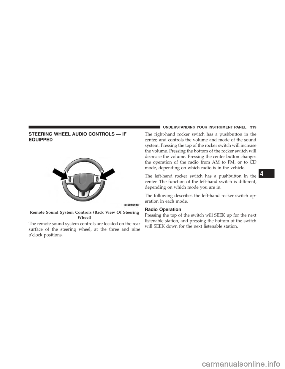
The remote sound system controls are located on the rear
surface of the steering wheel, at the three and nine
o’clock positions.The right-hand rocker switch has a pushbutton in the
center, and controls the volume and mode of the sound
system. Pressing the top of the rocker switch will increase
the volume. Pressing the bottom of the rocker switch will
decrease the volume. Pressing the center button changes
the operation of the radio from AM to FM, or to CD
mode, depending on which radio is in the vehicle.
The left-hand rocker switch has a pushbutton in the
center. The function of the left-hand switch is different,
depending on which mode you are in.
The following describes the left-hand rocker switch op-
eration in each mode.
Radio Operation
Pressing the top of the switch will SEEK up for the next
listenable station, and pressing the bottom of the switch
will SEEK down for the next listenable station.Remote Sound System Controls (Back View Of Steering
Wheel)
4
UNDERSTANDING YOUR INSTRUMENT PANEL 319
Page 350 of 562

▫Flowing/Rising Water ................. 363
▫ Shallow Standing Water ............... 364
� Power Steering ....................... 365
▫ Power Steering Fluid Check ............. 366
� Parking Brake ........................ 367
� Anti-Lock Brake System (ABS) ............ 369
▫ Anti-Lock Brake Warning Light .......... 371
� Electronic Brake Control System ........... 371
▫ Traction Control System (TCS) ........... 371
▫ Brake Assist System (BAS) .............. 372
▫ Electronic Stability Control (ESC) ......... 373
� Tire Safety Information ................. 377
▫ Tire Markings ....................... 377 ▫
Tire Identification Number (TIN) ......... 380
▫ Tire Terminology And Definitions ......... 381
▫ Tire Loading And Tire Pressure .......... 382
� Tires — General Information ............. 386
▫ Tire Pressure ....................... 386
▫ Tire Inflation Pressures ................ 387
▫ Tire Pressures For High-Speed Operation . . . 388
▫ Radial-Ply Tires ..................... 389
▫ Spare Tire Matching Original Equipped Tire
And Wheel – If Equipped .............. 389
▫ Compact Spare Tire – If Equipped ........ 390
▫ Full Size Spare – If Equipped ............ 391
▫ Limited-Use Spare – If Equipped ......... 391
348 STARTING AND OPERATING
Page 360 of 562

The transmission shift lever has only PARK, REVERSE,
NEUTRAL, and DRIVE shift positions. Manual down-
shifts can be made using the Electronic Range Select
(ERS) shift control (refer to “Electronic Range Select (ERS)
Operation” in this section). Moving the lever to the left or
right (–/ +) while in the DRIVE position will select the
highest available transmission gear, and will display that
gear in the instrument cluster as 6, 5, 4, 3, 2, 1.
Gear Ranges
Do not race the engine when moving the shift lever from
PARK or NEUTRAL positions into another gear range.
PARK
This range supplements the parking brake by locking the
transmission. The engine can be started in this gear.
Never attempt to use PARK while the vehicle is in
motion. Apply the parking brake when leaving the
vehicle in this gear.When parking on a flat surface, place the shift lever in the
PARK position first, and then apply the parking brake.
When parking on a hill, it is important to set the parking
brake before placing the shift lever in PARK, otherwise
the load on the transmission locking mechanism may
make it difficult to move the shift lever out of PARK. As
an added precaution, turn the front wheels toward the
curb on a downhill grade, and away from the curb on an
uphill grade.
WARNING!
•Never use the PARK position as a substitute for
the parking brake. Always apply the parking
brake fully when parked to guard against vehicle
movement and possible injury or damage.
(Continued)
358 STARTING AND OPERATING