Page 334 of 562

CAUTION!
Interior air enters the Rear Manual Climate Control
system through an intake grille, located in the right
side trim panel behind the third row seats. The
heater outlets are located in the right side trim panel,
just behind the sliding door. Do not block or place
objects directly in front of the inlet grille or heater
outlets. The electrical system could overload, causing
damage to the blower motor.
Rear Temperature Control
The rear mode selectionREAR,allows the settings to be
controlled by the rear mode control knob.
To change the temperature in the rear of the vehicle,
rotate the temperature control knob counterclockwise for
cold air, and clockwise for heated air. When rear controls are locked by the front system, the
lock symbol on the temperature knob is illuminated, and
the rear overhead adjustments are inoperable.
Rear Mode Control
Headliner Mode
Air comes from the outlets in the headliner. Each of
these outlets can be individually adjusted to direct
the flow of air. Moving the air vanes of the outlets to one
side will shut off the airflow.
Bi-Level Mode Air comes from both the headliner outlets and the
floor outlets.
NOTE: In many temperature positions, the BI-LEVEL
mode is designed to provide cooler air out of the head-
liner outlets and warmer air from the floor outlets.
332 UNDERSTANDING YOUR INSTRUMENT PANEL
Page 344 of 562

CAUTION!
Interior air enters the Rear Automatic Temperature
Control System through an intake grille, located in
the right side trim panel behind the third row seats.
The heater outlets are located in the right side trim
panel, just behind the sliding door. Do not block or
place objects directly in front of the inlet grille or
heater outlets. The electrical system could overload
causing damage to the blower motor.
Rear Temperature Control
To change the temperature in the rear of the vehicle,
rotate the temperature knob counterclockwise to lower
the temperature, and clockwise to increase the tempera-
ture. The rear temperature settings are displayed in the
front ATC panel.When rear controls are locked by the front system, the
Rear Temperature Lock symbol on the temperature knob
is illuminated and any rear overhead adjustments are
ignored.
Rear Mode Control
Auto Mode
The rear system automatically maintains the correct
mode and comfort level desired by the rear seat occu-
pants.
Headliner Mode
Air comes from the outlets in the headliner. Each of
these outlets can be individually adjusted to direct
the flow of air. Moving the air vanes of the outlets to one
side will shut off the airflow.
Bi-Level Mode Air comes from both the headliner outlets and the
floor outlets.
342 UNDERSTANDING YOUR INSTRUMENT PANEL
Page 440 of 562

HAZARD WARNING FLASHERS
The Hazard Warning flasher switch is located in the
lower center area of the instrument panel.Press the switch to turn on the Hazard Warning
flasher. When the switch is activated, all directional
turn signals will flash on and off to warn oncoming
traffic of an emergency. Press the switch a second time to
turn off the Hazard Warning flashers.
This is an emergency warning system and it should not
be used when the vehicle is in motion. Use it when your
vehicle is disabled and it is creating a safety hazard for
other motorists.
When you must leave the vehicle to seek assistance, the
Hazard Warning flashers will continue to operate even
though the ignition is placed in the OFF position.
NOTE: With extended use the Hazard Warning flashers
may wear down your battery.
IF YOUR ENGINE OVERHEATS
In any of the following situations, you can reduce the
potential for overheating by taking the appropriate ac-
tion.
•On the highways — slow down.
•In city traffic — while stopped, place the transmission
in NEUTRAL, but do not increase engine idle speed.
NOTE: There are steps that you can take to slow down
an impending overheat condition:
•If your air conditioner (A/C) is on, turn it off. The A/C
system adds heat to the engine cooling system and
turning the A/C off can help remove this heat.
•You can also turn the temperature control to maximum
heat, the mode control to floor and the blower control
to high. This allows the heater core to act as a
supplement to the radiator and aids in removing heat
from the engine cooling system.
438 WHAT TO DO IN EMERGENCIES
Page 508 of 562

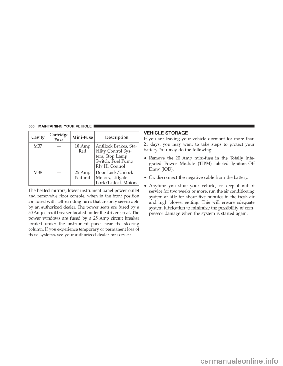
CavityCartridge
Fuse Mini-Fuse Description
M37 — 10 Amp RedAntilock Brakes, Sta-
bility Control Sys-
tem, Stop Lamp
Switch, Fuel Pump
Rly Hi Control
M38 — 25 Amp NaturalDoor Lock/Unlock
Motors, Liftgate
Lock/Unlock Motors
The heated mirrors, lower instrument panel power outlet
and removable floor console, when in the front position
are fused with self-resetting fuses that are only serviceable
by an authorized dealer. The power seats are fused by a
30 Amp circuit breaker located under the driver’s seat. The
power windows are fused by a 25 Amp circuit breaker
located under the instrument panel near the steering
column. If you experience temporary or permanent loss of
these systems, see your authorized dealer for service.
VEHICLE STORAGE
If you are leaving your vehicle dormant for more than
21 days, you may want to take steps to protect your
battery. You may do the following:
•Remove the 20 Amp mini-fuse in the Totally Inte-
grated Power Module (TIPM) labeled Ignition-Off
Draw (IOD).
•Or, disconnect the negative cable from the battery.
•Anytime you store your vehicle, or keep it out of
service for two weeks or more, run the air conditioning
system at idle for about five minutes in the fresh air
and high blower setting. This will ensure adequate
system lubrication to minimize the possibility of com-
pressor damage when the system is started again.
506 MAINTAINING YOUR VEHICLE