Page 375 of 566

power may also be reduced to assist in counteracting the
condition of oversteer or understeer and help the vehicle
maintain the desired path.
The ESC uses sensors in the vehicle to determine the path
that the driver intends to steer the vehicle and compares
it to the actual path of the vehicle. When the actual path
does not match the intended path, the ESC applies the
brake of the appropriate wheel to assist in counteracting
the condition of oversteer or understeer.
•Oversteer - when the vehicle is turning more than
appropriate for the steering wheel position.
•Understeer - when the vehicle is turning less than
appropriate for the steering wheel position.
ESC Operating Modes
The ESC system has two available operating modes:ESC On
This is the normal operating mode for the ESC. When-
ever the vehicle is started, the ESC system will be in this
mode. This mode should be used for most driving
conditions. The ESC should only be turned OFF for
specific reasons as noted in the following paragraphs.
Partial Off
The “Partial Off” mode is intended for times when a
more spirited driving experience is desired. It is also
intended for driving in deep snow, sand, or gravel. This
mode disables the TCS portion of the ESC and raises the
threshold for ESC activation, which allows for more
wheel spin than what ESC normally allows.
5
STARTING AND OPERATING 373
Page 380 of 566

Malfunction Indicator Light” begins to flash during ac-
celeration, ease up on the accelerator and apply as little
throttle as possible. Be sure to adapt your speed and
driving to the prevailing road conditions.
NOTE:
•The “ESC Activation/Malfunction Indicator Light”
and the “ESC OFF Indicator Light” come on momen-
tarily each time the ignition switch is turned ON.
•Each time the ignition is turned ON, the ESC system
will be ON even if it was turned off previously.
•The ESC system will make buzzing or clicking sounds
when it is active. This is normal; the sounds will stop
when ESC becomes inactive following the maneuver
that caused the ESC activation.The “ESC OFF Indicator Light” indicates the
Electronic Stability Control (ESC) is off.
Synchronizing ESC
If the power supply is interrupted (battery
disconnected or discharged), the “ESC
Activation/Malfunction Indicator Light” may
illuminate with the engine running. If this
should occur, turn the steering wheel completely to the
left and then to the right. The “ESC Activation/
Malfunction Indicator Light” should go out. However, if
the light remains on, have the ESC and BAS checked at
your authorized dealer as soon as possible.
378 STARTING AND OPERATING
Page 468 of 566

MAINTENANCE PROCEDURES
The pages that follow contain therequiredmaintenance
services determined by the engineers who designed your
vehicle.
Besides those maintenance items specified in the fixed
maintenance schedule, there are other components which
may require servicing or replacement in the future.
CAUTION!
•Failure to properly maintain your vehicle or per-
form repairs and service when necessary could
result in more costly repairs, damage to other
components or negatively impact vehicle perfor-
mance. Immediately have potential malfunctions
examined by an authorized Chrysler Group LLC
dealership or qualified repair center.
(Continued)
CAUTION! (Continued)
•Your vehicle has been built with improved fluids
that protect the performance and durability of
your vehicle and also allow extended maintenance
intervals. Do not use chemical flushes in these
components as the chemicals can damage your
engine, transmission, power steering or air condi-
tioning. Such damage is not covered by the New
Vehicle Limited Warranty. If a flush is needed
because of component malfunction, use only the
specified fluid for the flushing procedure.
466 MAINTAINING YOUR VEHICLE
Page 499 of 566
CAUTION!
•When installing the integrated power module
cover, it is important to ensure the cover is prop-
erly positioned and fully latched. Failure to do so
may allow water to get into the integrated power
module and possibly result in an electrical system
failure.
•When replacing a blown fuse, it is important to
use only a fuse having the correct amperage rating.
The use of a fuse with a rating other than indicated
may result in a dangerous electrical system over-
load. If a properly rated fuse continues to blow, it
indicates a problem in the circuit that must be
corrected.
Cavity CartridgeFuseMini-
Fuse Description
1 — — Fuse – Spare
2 40 Amp Green — Radiator Fan #1
3 50 Amp Red — Power Steering #1
4 30 Amp Pink — Starter
5 40 Amp Green — Anti-Lock Brakes
6 — — Fuse – Spare
7 — — Fuse – Spare
8 — — Fuse – Spare
9 — 20 Amp YellowAll-Wheel Drive
Module – If Equipped
10 — 10 Amp RedSecurity
7
MAINTAINING YOUR VEHICLE 497
Page 500 of 566
Cavity CartridgeFuseMini-
Fuse Description
11 — 20 Amp YellowHorns
12 — 10 Amp RedAir Conditioning
Clutch
13 — — Fuse – Spare
14 — 25 Amp NaturalAnti-Lock Brakes
15 — 25 Amp NaturalTransmission
16 — — Fuse – Spare
18 50 Amp Red — Radiator Fan #2
19 50 Amp Red — Power Steering #2
20 30 Amp Pink — Wiper MotorCavity Cartridge
FuseMini-
Fuse Description
21 30 Amp Pink — Headlamp Washers
22 — — Fuse – Spare
23 — — Fuse – Spare
24 — — Fuse – Spare
28 — 25 Amp NaturalFuel Pump
29 — 15 Amp BlueTransmission Shifter
30 — — Fuse – Spare
31 — 25 Amp NaturalEngine Module
32 — — Fuse – Spare
33 — — Fuse – Spare
34 — 25 Amp NaturalPowertrain #1
498 MAINTAINING YOUR VEHICLE
Page 501 of 566
Cavity CartridgeFuseMini-
Fuse Description
35 — 20 Amp YellowPowertrain #2
36 — 10 Amp RedAnti-Lock Brake
Module
37 — 10 Amp RedEngine Controller/
Rad Fan Relays
38 — 10 Amp RedAirbag Module
39 — 10 Amp RedPower Steering
Module/AC Clutch
RelayCavity Cartridge
FuseMini-
Fuse Description
48 — 10 Amp RedAWD Module/Front
Axle Disconnect
49 — — Fuse – Spare
50 — — Fuse – Spare
51 — 20 Amp YellowVacuum Pump
52 — — Fuse – Spare
53 — — Fuse – Spare
7
MAINTAINING YOUR VEHICLE 499
Page 505 of 566
Cavity CartridgeFuseMini-
Fuse Description
34 — 10 Amp RedSteering Column
Module/Clock
35 — 10 Amp RedBattery Sensor
36 — — Fuse — Spare
37 — 15 Amp BlueRadio
38 — 20 Amp YellowPower Outlet Inside
Arm Rest
40 — — Fuse — Spare
41 — — Fuse — Spare
42 30 Amp Pink — Rear Defrost
43 — 25 Amp NaturalRear Heated Seats/
Steering WheelCavity Cartridge
FuseMini-
Fuse Description
44 — 10 Amp RedPark Assist/Blind
Spot/Camera
45 — 15 Amp BlueCluster/Rearview
Mirror/Compass
46 — 10 Amp RedAdaptive Cruise Con-
trol
47 — 10 Amp RedAdaptive Front Light-
ing
48 — 20 Amp YellowActive Suspension
49 — — Fuse — Spare
50 — — Fuse — Spare
51 — 20 Amp YellowFront Heated Seats
7
MAINTAINING YOUR VEHICLE 503
Page 514 of 566
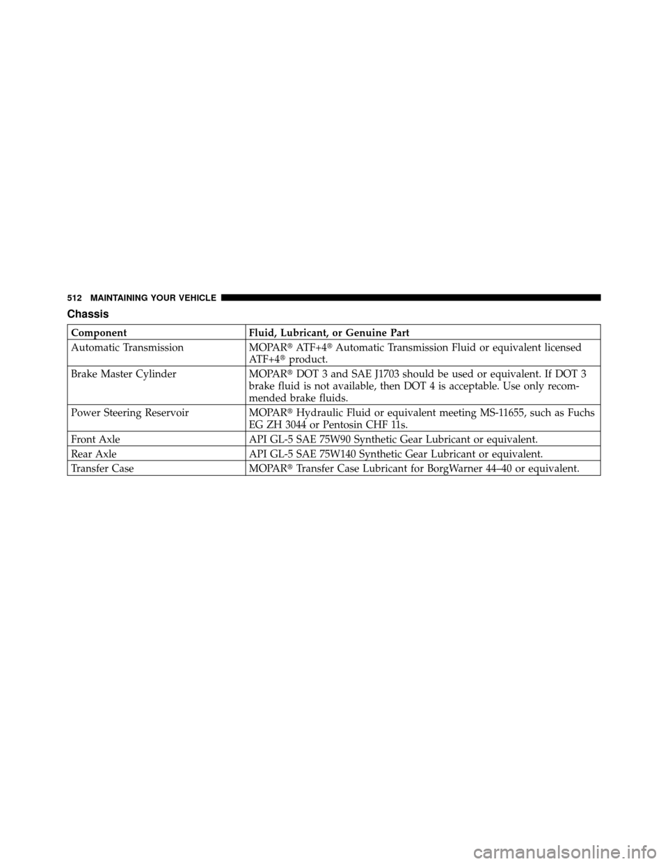
Chassis
ComponentFluid, Lubricant, or Genuine Part
Automatic Transmission MOPAR�ATF+4�Automatic Transmission Fluid or equivalent licensed
ATF+4� product.
Brake Master Cylinder MOPAR�DOT 3 and SAE J1703 should be used or equivalent. If DOT 3
brake fluid is not available, then DOT 4 is acceptable. Use only recom-
mended brake fluids.
Power Steering Reservoir MOPAR�Hydraulic Fluid or equivalent meeting MS-11655, such as Fuchs
EG ZH 3044 or Pentosin CHF 11s.
Front Axle API GL-5 SAE 75W90 Synthetic Gear Lubricant or equivalent.
Rear Axle API GL-5 SAE 75W140 Synthetic Gear Lubricant or equivalent.
Transfer Case MOPAR�Transfer Case Lubricant for BorgWarner 44–40 or equivalent.
512 MAINTAINING YOUR VEHICLE