Page 164 of 573
5. Pull release strap marked “4” and tumble the seat
rearward into the storage bin.
To Unfold Third Row Seats
1. Pull up on the assist strap to lift the seat out of the
storage bin and push the seat forward until the anchors
latch.
2. Pull release strap marked “2” to unlock the recliner.Release Strap “4”
Stowed Third Row Seat
3
UNDERSTANDING THE FEATURES OF YOUR VEHICLE 161
Page 177 of 573

•Headlight Beams Low/High
•Flash-To-Pass (Optical Horn)
•Front and Rear Wipers — Washer Functions
Turn Signals
Move the multifunction lever up or down and the arrows
on each side of the instrument cluster flash to show
proper operation of the front and rear turn signal lights.
NOTE:If either light remains on and does not flash, or
there is a very fast flash rate, check for a defective outside
light bulb. If an indicator fails to light when the lever is
moved, it would suggest that the indicator bulb is
defective.
Lane Change Assist
Tap the lever up or down once, without moving beyond
the detent, and the turn signal (right or left) will flash
three times then automatically turn off.
Turn Signal Warning
If the vehicle electronics sense that the vehicle has
traveled at over 18 mph (29 km/h) for approximately
1 mile (1.6 km) with the turn signals on, a chime will
sound to alert the driver.
High/Low Beam Switch
When the headlights are turned on, pushing the multi-
function lever toward the instrument panel will switch
from low beams to high beams. Pulling back to the
neutral position returns the headlights to the low beam
operation.
Flash-To-Pass
You can signal another vehicle with your headlights by
lightly pulling the multifunction lever toward you. This
will turn on the high beam headlights until the lever is
released.
174 UNDERSTANDING THE FEATURES OF YOUR VEHICLE
Page 178 of 573

SmartBeam™ — If Equipped
The SmartBeam™ system provides increased forward
lighting at night by automating high beam control
through the use of a digital camera mounted on the
inside rearview mirror. This camera detects vehicle spe-
cific light and automatically switches from high beams to
low beams until the approaching vehicle is out of view.
To Activate
1. Select “Automatic High Beams — ON” through the
EVIC. Refer to “Electronic Vehicle Information Center
(EVIC)/Customer-Programmable Features” in “Under-
standing Your Instrument Panel” for further information.
2. Rotate the headlight switch counterclockwise to the
AUTO (A) position.
3. Push the multifunction lever away from you to switch
the headlights to the high beam position. Refer to “Mul-
tifunction Lever” in this section for further information.NOTE:
This system will not activate until the vehicle is
at, or above, 25 mph (40 km/h).
To Deactivate
Perform either of the following steps to deactivate the
SmartBeam™ system.
1. Select “Automatic High Beams — OFF” through the
EVIC. Refer to “Electronic Vehicle Information Center
(EVIC)/Customer-Programmable Features” in “Under-
standing Your Instrument Panel” for further information.
2. Pull the multifunction lever toward you to switch the
headlights from the high beam to the low beam position.
3. Rotate the headlight switch clockwise from the AUTO
(A) to the on position.
NOTE: Broken, muddy or obstructed headlights and
taillights of vehicles in the field of view will cause
headlights to remain on longer (closer to the vehicle).
3
UNDERSTANDING THE FEATURES OF YOUR VEHICLE 175
Page 179 of 573
Also, dirt, film and other obstructions on the windshield
or camera lens will cause the system to function
improperly.
WINDSHIELD WIPERS AND WASHERS
The wipers and washers are operated by a switch within
the multifunction lever. Rotate the end of the multifunc-
tion lever to select the desired wiper speed.
NOTE:Always remove any buildup of snow that pre-
vents the windshield wiper blades from returning to the
off position. If the windshield wiper switch is turned off
and the blades cannot return to the off position, damage
to the wiper motor may occur.
Mist, Front Wiper And Washer
Use the Mist feature when weather conditions make
occasional usage of the wipers necessary.
Press the end of the multifunction lever inward (toward
the steering column) to the first detent and release for a
single wiping cycle. To use the Washer, push on the end
Washer And Wiper Controls
176 UNDERSTANDING THE FEATURES OF YOUR VEHICLE
Page 183 of 573

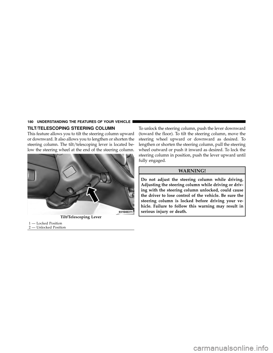
TILT/TELESCOPING STEERING COLUMN
This feature allows you to tilt the steering column upward
or downward. It also allows you to lengthen or shorten the
steering column. The tilt/telescoping lever is located be-
low the steering wheel at the end of the steering column.
To unlock the steering column, push the lever downward
(toward the floor). To tilt the steering column, move the
steering wheel upward or downward as desired. To
lengthen or shorten the steering column, pull the steering
wheel outward or push it inward as desired. To lock the
steering column in position, push the lever upward until
fully engaged.
WARNING!
Do not adjust the steering column while driving.
Adjusting the steering column while driving or driv-
ing with the steering column unlocked, could cause
the driver to lose control of the vehicle. Be sure the
steering column is locked before driving your ve-
hicle. Failure to follow this warning may result in
serious injury or death.
Tilt/Telescoping Lever
1 — Locked Position
2 — Unlocked Position
180 UNDERSTANDING THE FEATURES OF YOUR VEHICLE
Page 185 of 573
WARNING! (Continued)
•Do not place anything on the steering wheel that
insulates against heat, such as a blanket or cush-
ion. This may cause the steering wheel heater to
overheat.
ADJUSTABLE PEDALS — IF EQUIPPED
The adjustable pedals system is designed to allow a
greater range of driver comfort for steering wheel tilt and
seat position. This feature allows the brake, accelerator,
and clutch pedals (if equipped) to move toward or away
from the driver to provide improved position with the
steering wheel.
The switch is located on the left side of the steering
column.Press the switch forward to move the pedals forward
(toward the front of the vehicle).
Press the switch rearward to move the pedals rearward
(toward the driver).
•The pedals can be adjusted with the ignition OFF.
Adjustable Pedal Switch
182 UNDERSTANDING THE FEATURES OF YOUR VEHICLE
Page 198 of 573

WARNING! (Continued)
•Before using the ParkSense�Rear Park Assist
System, it is strongly recommended that the ball
mount and hitch ball assembly is disconnected
from the vehicle when the vehicle is not used for
towing. Failure to do so can result in injury or
damage to vehicles or obstacles because the hitch
ball will be much closer to the obstacle than the
rear fascia when the warning display turns on the
single flashing arc and sounds the continuous
tone. Also, the sensors could detect the ball mount
and hitch ball assembly, depending on its size and
shape, giving a false indication that an obstacle is
behind the vehicle.
PARKVIEW� REAR BACK UP CAMERA —
IF EQUIPPED
Your vehicle may be equipped with the ParkView� Rear
Back Up Camera that allows you to see an on-screen
image of the rear surroundings of your vehicle whenever
the shift lever is put into REVERSE. The image will be
displayed on the Navigation/Multimedia radio display
screen along with a caution note to “check entire sur-
roundings” across the top of the screen. After five sec-
onds this note will disappear. The ParkView� camera is
located on the rear of the vehicle above the rear License
plate.
When the vehicle is shifted out of REVERSE, the rear
camera mode is exited and the navigation or audio screen
appears again.
3
UNDERSTANDING THE FEATURES OF YOUR VEHICLE 195
Page 214 of 573

NOTE:If three consecutive sunroof close attempts re-
sult in Pinch Protect reversals, the fourth close attempt
will be a Manual Close movement with Pinch Protect
disabled.
Pinch Protect Override
If a known obstruction (ice, debris, etc.) prevents closing
the sunroof, press the switch forward and hold for two
seconds after the reversal occurs. This allows the sunroof
to move toward the closed position.
NOTE: Pinch protection is disabled while the switch is
pressed.
Venting Sunroof — Express
Press and release the “Vent” button, and the sunroof will
open to the vent position. This is called “Express Vent”,
and will occur regardless of sunroof position. During
Express Vent operation, any movement of the switch will
stop the sunroof.
Sunshade Operation
The sunshade can be opened manually. However, the
sunshade will open automatically as the sunroof opens.
NOTE: The sunshade cannot be closed if the sunroof is
open.
Wind Buffeting
Wind buffeting can be described as the perception of
pressure on the ears or a helicopter-type sound in the
ears. Your vehicle may exhibit wind buffeting with the
windows down, or the sunroof (if equipped) is in certain
open or partially open positions. This is a normal occur-
rence and can be minimized. If the buffeting occurs with
the rear windows open, open the front and rear windows
together to minimize the buffeting. If the buffeting occurs
with the sunroof open, adjust the sunroof opening to
minimize the buffeting or open any window.
3
UNDERSTANDING THE FEATURES OF YOUR VEHICLE 211