Page 271 of 573
NOTE:The system will display the last known outside
temperature when starting the vehicle and may need to
be driven several minutes before the updated tempera-
ture is displayed. Engine temperature can also affect the
displayed temperature; therefore, temperature readings
are not updated when the vehicle is not moving.
CMTC Reset Buttons
CMTC Reset Button
Press the STEP button located on the steering wheel to
scroll through sub menus (i.e., Trip Functions: AVG Fuel
Economy, DTE, Elapsed Time, and Units).
To reset the display shown, turn the ignition switch to the
ON position, then press and hold the RESET button for
approximately two seconds. When the appropriate conditions exist, the following
messages will display:
NE
.............. Eight-point compass headings are
displayed (N, S, E, W, NE, NW, SE, SW)
14°F ............ T emperature (Fahrenheit or Celsius)
AV G ......... Average Fuel Economy (U.S. or Metric)
DTE ....................... Distance to Empty
ET ............................ Elapsed Time
P .......................... Park Assist On/Off
Should this wrench symbol display with the
letter Pnext to it, your Park Assist System
needs servicing. Contact an authorized dealer.
CMTC Trip Odometer (ODO)
This display shows the distance traveled since the last
reset. Press and release the STEP button on the steering
wheel to switch from odometer to Trip A or Trip B or to
ECO. Press and hold the RESET button while the
odometer/trip odometer is displayed to reset.
268 UNDERSTANDING YOUR INSTRUMENT PANEL
Page 274 of 573
2. Press and hold the RESET button (for approximately
10 seconds) until the current variance zone number is
displayed.
3. Release the RESET button, then press and hold again
for approximately 10 seconds, until the direction is
displayed, with the CAL indicator on continuously in the
display.
4. To complete the compass calibration, drive the vehicle
in one or more complete 360–degree circles, under 5 mph
(8 km/h) in an area free from power lines and large
metallic objects, until the CAL indicator turns off. The
compass will now function normally.
ELECTRONIC VEHICLE INFORMATION CENTER
(EVIC) — IF EQUIPPED
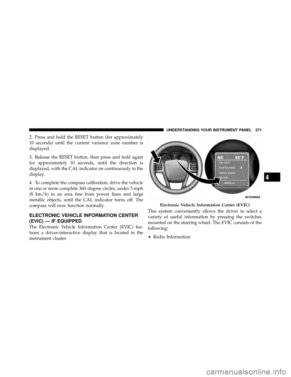
The Electronic Vehicle Information Center (EVIC) fea-
tures a driver-interactive display that is located in the
instrument cluster.This system conveniently allows the driver to select a
variety of useful information by pressing the switches
mounted on the steering wheel. The EVIC consists of the
following:
•Radio Information
Electronic Vehicle Information Center (EVIC)
4
UNDERSTANDING YOUR INSTRUMENT PANEL 271
Page 275 of 573
•Fuel Economy
•Vehicle Speed
•Trip Info
•Tire PSI
•Vehicle Info
•Messages
•Units
•System Setup (Personal Settings)
•Turn Menu OffThe system allows the driver to select information by
pressing the following buttons mounted on the steering
wheel:
EVIC Steering Wheel Buttons
272 UNDERSTANDING YOUR INSTRUMENT PANEL
Page 290 of 573

Entry (RKE) transmitter UNLOCK button. When Driver
Door 1st Press is selected, you must press the RKE
transmitter UNLOCK button twice, to unlock the passen-
ger’s doors. WhenAll Doors 1st Press is selected, all of
the doors will unlock on the first press of the RKE
transmitter UNLOCK button. To make your selection,
press and release the SELECT button until a check-mark
appears next to the feature showing the system has been
activated or the check-mark is removed showing the
system has been deactivated.
RKE Linked To Memory
When this feature is selected the memory seat, mirror,
and radio settings will return to the memory set position
when the RKE transmitter UNLOCK button is pressed. If
this feature is not selected then the memory seat, mirror,
and radio settings can only return to the memory set
position using the door mounted switch. To make your
selection, press and release the SELECT button until a
check-mark appears next to the feature showing the system has been activated or the check-mark is removed
showing the system has been deactivated.
Remote Start Comfort Sys.
When this feature is selected and the remote start is
activated, the heated steering wheel and driver heated
seat features will automatically turn on in cold weather.
In warm weather, the driver vented seat feature will
automatically turn on when the remote start is activated.
These features will stay on through the duration of
remote start or until the key is turned to RUN. To make
your selection, press and release the SELECT button until
a check-mark appears next to the feature showing the
system has been activated or the check-mark is removed
showing the system has been deactivated.
Horn With Remote Lock
When this feature is selected, a short horn sound will
occur when the RKE transmitter LOCK button is pressed.
This feature may be selected with or without the Flash
4
UNDERSTANDING YOUR INSTRUMENT PANEL 287
Page 329 of 573
STEERING WHEEL AUDIO CONTROLS —
IF EQUIPPEDThe remote sound system controls are located on the rear
surface of the steering wheel, at the three and nine
o’clock positions.
The right-hand rocker switch has a pushbutton in the
center, and controls the volume and mode of the sound
system. Pressing the top of the rocker switch will increase
the volume. Pressing the bottom of the rocker switch will
decrease the volume. Pressing the center button changes
the operation of the radio from AM to FM, or to CD
mode, depending on which radio is in the vehicle.
The left-hand rocker switch has a pushbutton in the
center. The function of the left-hand switch is different,
depending on which mode you are in.
The following describes the left-hand rocker switch op-
eration in each mode.
Remote Sound System Controls(Back View Of Steering Wheel)
326 UNDERSTANDING YOUR INSTRUMENT PANEL
Page 357 of 573
�Driving Through Water ................. 372
▫ Flowing/Rising Water ................. 372
▫ Shallow Standing Water ............... 372
� Power Steering ....................... 374
▫ Power Steering Fluid Check ............. 375
� Parking Brake ........................ 375
� Anti-Lock Brake System (ABS) ............ 377
▫ Anti-Lock Brake Warning Light .......... 379
� Electronic Brake Control System ........... 380
▫ Traction Control System (TCS) ........... 380
▫ Brake Assist System (BAS) .............. 381
▫ Electronic Stability Control (ESC) ......... 382�
Tire Safety Information ................. 385
▫ Tire Markings ....................... 385
▫ Tire Identification Number (TIN) ......... 389
▫ Tire Terminology And Definitions ......... 390
▫ Tire Loading And Tire Pressure .......... 391
� Tires — General Information ............. 395
▫ Tire Pressure ....................... 395
▫ Tire Inflation Pressures ................ 396
▫ Tire Pressures For High-Speed Operation . . . 397
▫ Radial-Ply Tires ..................... 398
▫ Spare Tire Matching Original Equipped Tire
And Wheel – If Equipped .............. 398
▫ Compact Spare Tire – If Equipped ........ 399
354 STARTING AND OPERATING
Page 377 of 573
POWER STEERING
The standard power steering system will give you good
vehicle response and increased ease of maneuverability
in tight spaces. The system will provide mechanical
steering capability if power assist is lost.
If for some reason the power assist is interrupted, it will
still be possible to steer your vehicle. Under these condi-
tions, you will observe a substantial increase in steering
effort, especially at very low vehicle speeds and during
parking maneuvers.
NOTE:
•Increased noise levels at the end of the steering wheel
travel are considered normal and do not indicate that
there is a problem with the power steering system.
•Upon initial start-up in cold weather, the power steer-
ing pump may make noise for a short amount of time.
This is due to the cold, thick fluid in the steering
system. This noise should be considered normal, and it
does not in any way damage the steering system.
WARNING!
Continued operation with reduced power steering
assist could pose a safety risk to yourself and others.
Service should be obtained as soon as possible.
CAUTION!
Prolonged operation of the steering system at the end
of the steering wheel travel will increase the steering
fluid temperature and it should be avoided when
possible. Damage to the power steering pump may
occur.
374 STARTING AND OPERATING
Page 385 of 573
WARNING! (Continued)
•The capabilities of a BAS-equipped vehicle must
never be exploited in a reckless or dangerous
manner which could jeopardize the user’s safety
or the safety of others.
Electronic Stability Control (ESC)
The Electronic Stability Control (ESC) enhances direc-
tional control and stability of the vehicle under various
driving conditions. ESC corrects for over/under steering
of the vehicle by applying the brake of the appropriate
wheel to assist in counteracting the over/under steer
condition. Engine power may also be reduced to help the
vehicle maintain the desired path.
ESC uses sensors in the vehicle to determine the vehicle
path intended by the driver and compares it to the actual
path of the vehicle. When the actual path does not matchthe intended path, ESC applies the brake of the appro-
priate wheel to assist in counteracting the oversteer or
understeer condition.
•Oversteer - when the vehicle is turning more than
appropriate for the steering wheel position.
•Understeer - when the vehicle is turning less than
appropriate for the steering wheel position.
WARNING!
•The Electronic Stability Control (ESC) cannot pre-
vent the natural laws of physics from acting on the
vehicle, nor can it increase the traction afforded by
prevailing road conditions.
•ESC cannot prevent collisions, including those
resulting from excessive speed in turns, driving on
very slippery surfaces, or hydroplaning.
(Continued)
382 STARTING AND OPERATING