2011 CHEVROLET HHR Remote
[x] Cancel search: RemotePage 291 of 430

Black plate (15,1)Chevrolet HHR Owner Manual - 2011
A. Windshield Washer Fluid Reservoir. See“Adding
Washer Fluid” underWindshield Washer Fluidon
page 6‑30.
B. Pressure Cap. See Cooling System on page 6‑22.
C. Coolant Recovery Tank. See “Checking Coolant”
under Engine Coolant on page 6‑24.
D. Engine Air Cleaner/Filter. See Engine Air Cleaner/
Filter on page 6‑20.
E. Electric Engine Cooling Fan (Out of View). See Cooling System Cooling System on page 6‑22.
F. Engine Oil Fill Cap. See “When to Add Engine Oil”
under Engine Oil on page 6‑16. G. Engine Oil Dipstick (Out of View). See
“Checking
Engine Oil” underEngine Oil on page 6‑16.
H. Brake Master Cylinder Reservoir. See Brakeson
page 6‑30and Hydraulic Clutch on page 6‑22.
I. Remote Positive (+) Terminal. See Jump Starting
on page 6‑34.
J. Engine Compartment Fuse Block. See Engine
Compartment Fuse Block on page 6‑104.
K. Remote Negative (−) Terminal (Out of View). See Jump Starting on page 6‑34.
6-15
Page 311 of 430
Black plate (35,1)Chevrolet HHR Owner Manual - 2011
4. Open the hood on the other vehicle and locate thepositive (+) and negative (−) terminal locations on
that vehicle.
You will not see the battery of your vehicle under
the hood. It is located in the rear cargo area. You
will not need to access your battery for jump
starting. The vehicle has a remote positive (+) and
a remote negative (−) jump starting terminal.
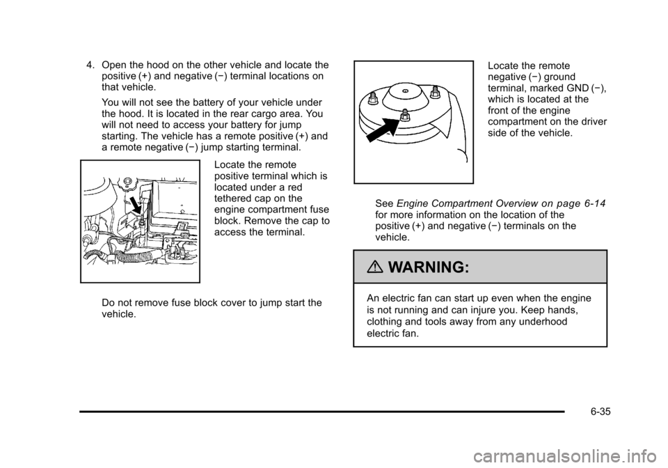
Locate the remote
positive terminal which is
located under a red
tethered cap on the
engine compartment fuse
block. Remove the cap to
access the terminal.
Do not remove fuse block cover to jump start the
vehicle.
Locate the remote
negative (−) ground
terminal, marked GND (−),
which is located at the
front of the engine
compartment on the driver
side of the vehicle.
See Engine Compartment Overview
on page 6‑14for more information on the location of the
positive (+) and negative (−) terminals on the
vehicle.
{WARNING:
An electric fan can start up even when the engine
is not running and can injure you. Keep hands,
clothing and tools away from any underhood
electric fan.
6-35
Page 312 of 430
Black plate (36,1)Chevrolet HHR Owner Manual - 2011
{WARNING:
Using a match near a battery can cause battery
gas to explode. People have been hurt doing this,
and some have been blinded. Use a flashlight if
you need more light.
Be sure the battery has enough water. You do not
need to add water to the battery installed in your
new vehicle. But if a battery has filler caps, be
sure the right amount of fluid is there. If it is low,
add water to take care of that first. If you don't,
explosive gas could be present.
Battery fluid contains acid that can burn you. Do
not get it on you. If you accidentally get it in your
eyes or on your skin, flush the place with water
and get medical help immediately.
{WARNING:
Fans or other moving engine parts can injure you
badly. Keep your hands away from moving parts
once the engine is running.
5. Check that the jumper cables do not have loose or missing insulation. If they do, you could get a
shock. The vehicles could be damaged too.
Before you connect the cables, here are some
basic things you should know. Positive (+) will go to
positive (+) or to a remote positive (+) terminal if
the vehicle has one. Negative (−) will go to a
heavy, unpainted metal engine part or to a remote
negative (−) terminal if the vehicle has one.
Do not connect positive (+) to negative (−) or you
will get a short that would damage the battery and
maybe other parts too. And do not connect the
negative (−) cable to the negative (−) terminal on
the dead battery because this can cause sparks.
6. Connect the red positive (+) cable to the positive (+) terminal location on the vehicle with the
dead battery. Use a remote positive (+) terminal if
the vehicle has one.
6-36
Page 313 of 430
Black plate (37,1)Chevrolet HHR Owner Manual - 2011
7. Do not let the other end touch metal. Connect it tothe positive (+) terminal of the good battery. Use a
remote positive (+) terminal if the vehicle has one.
8. Now connect the black negative (−) cable to the negative (−) terminal of the good battery. Use a
remote negative (−) terminal if the vehicle has one.
Do not let the other end touch anything until the
next step. The other end of the negative (−) cable
does not go to the dead battery. It goes to a heavy,
unpainted metal engine part or to a remote
negative (−) terminal on the vehicle with the dead
battery.
9. Connect the other end of the negative (−) cable to the negative (−) terminal location on the vehicle
with the dead battery. Your vehicle has a remote
negative (−) ground terminal marked GND (−).
10. Now start the vehicle with the good battery and run the engine for a while.
11. Try to start the vehicle that had the dead battery. If it will not start after a few tries, it probably needs
service.
Notice: If the jumper cables are connected or
removed in the wrong order, electrical shorting may
occur and damage the vehicle. The repairs would
not be covered by the vehicle warranty. Always
connect and remove the jumper cables in the
correct order, making sure that the cables do not
touch each other or other metal.
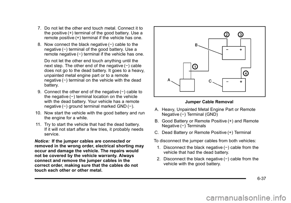
Jumper Cable Removal
A. Heavy, Unpainted Metal Engine Part or Remote Negative (−) Terminal (GND)
B. Good Battery or Remote Positive (+) and Remote Negative (−) Terminals
C. Dead Battery or Remote Positive (+) Terminal
To disconnect the jumper cables from both vehicles: 1. Disconnect the black negative (−) cable from the vehicle that had the dead battery.
2. Disconnect the black negative (−) cable from the vehicle with the good battery.
6-37
Page 335 of 430
Black plate (59,1)Chevrolet HHR Owner Manual - 2011
TPMS Sensor Matching Process
Each TPMS sensor has a unique identification code.
Any time you replace one or more of the TPMS sensors
or rotate the vehicle's tires, the identification codes
need to be matched to the new tire/wheel location. The
sensors are matched, to the tire/wheel locations, in the
following order: driver side front tire, passenger side
front tire, passenger side rear tire, and driver side rear
tire using a TPMS diagnostic tool. See your dealer for
service.
The TPMS sensors can also be matched to each tire/
wheel position by increasing or decreasing the tire's air
pressure. When increasing the tire's pressure, do not
exceed the maximum inflation pressure indicated on the
tire's sidewall. To decrease the tire's air-pressure use
the pointed end of the valve cap, a pencil-style air
pressure gauge, or a key.
You have two minutes to match each tire and wheel
position. If it takes longer than two minutes to match
any tire and wheel position, the matching process stops
and you need to start over.
The TPMS matching process is outlined below:1. Set the parking brake.
2. Turn the ignition switch to ON/RUN with the engine off. 3. Press and hold the Remote Keyless Entry (RKE)
transmitter's LOCK and UNLOCK buttons, at the
same time, for about five seconds to start the
TPMS learn mode. The horn sounds twice
indicating the TPMS receiver is ready and in
learn mode.
4. Start with the driver side front tire. The driver side front turn signal also comes on to indicate that
corner's sensor is ready to be learned.
5. Remove the valve cap from the tire's valve stem. Activate the TPMS sensor by increasing or
decreasing the tire's air pressure for about
eight seconds. The horn chirp, can take up to
30 seconds to sound. It chirps one time and then
all the turn signals flash one time to confirm the
sensor identification code has been matched to the
tire/wheel position.
6. The passenger side front turn signal comes on to indicate that corner sensor is ready to be learned.
Proceed to the passenger side front tire and repeat
the procedure in Step 5.
7. The passenger side rear turn signal comes on to indicate that corner sensor is ready to be learned.
Proceed to the passenger side rear tire and repeat
the procedure in Step 5.
6-59
Page 405 of 430
Black plate (7,1)Chevrolet HHR Owner Manual - 2011
Coverage
Services are provided up to 5 years/160 000 km
(100,000 miles), whichever comes first.
In the U.S., anyone driving the vehicle is covered. In
Canada, a person driving the vehicle without permission
from the owner is not covered.
Roadside Assistance is not a part of the New Vehicle
Limited Warranty. Chevrolet and General Motors of
Canada Limited reserve the right to make any changes
or discontinue the Roadside Assistance program at any
time without notification.
Chevrolet and General Motors of Canada Limited
reserve the right to limit services or payment to an
owner or driver if they decide the claims are made too
often, or the same type of claim is made many times.
Services Provided
.Emergency Fuel Delivery:Delivery of enough
fuel for the vehicle to get to the nearest service
station.
.Lock‐Out Service: Service to unlock the vehicle if
you are locked out. A remote unlock may be
available if you have OnStar
®. For security
reasons, the driver must present identification
before this service is given.
.Emergency Tow From a Public Road or
Highway: Tow to the nearest Chevrolet dealer for
warranty service, or if the vehicle was in a crash
and cannot be driven. Assistance is also given
when the vehicle is stuck in the sand, mud,
or snow.
.Flat Tire Change: Service to change a flat tire
with the spare tire. The spare tire, if equipped,
must be in good condition and properly inflated.
It is the owner's responsibility for the repair or
replacement of the tire if it is not covered by the
warranty.
.Battery Jump Start: Service to jump start a dead
battery.
Services Not Included in Roadside
Assistance
.Impound towing caused by violation of any laws.
.Legal fines.
.Mounting, dismounting, or changing of snow tires,
chains, or other traction devices.
.Towing or services for vehicles driven on a
non-public road or highway.
8-7
Page 415 of 430
Black plate (17,1)Chevrolet HHR Owner Manual - 2011
OnStar®
If your vehicle is equipped with an active OnStar
system, that system may also record data in crash or
near crash‐like situations. The OnStar Terms and
Conditions provides information on data collection and
use and is available in the OnStar glove box kit, at
www.onstar.com (U.S.) or www.onstar.ca (Canada),
or by pressing the
Qbutton and speaking to an
advisor.
Radio Frequency
Identification (RFID)
RFID technology is used in some vehicles for functions
such as tire pressure monitoring and ignition system
security, as well as in connection with conveniences
such as key fobs for remote door locking/unlocking and
starting, and in-vehicle transmitters for garage door
openers. RFID technology in GM vehicles does not use
or record personal information or link with any other
GM system containing personal information.
Radio Frequency Statement
This vehicle has systems that operate on a radio
frequency that comply with Part 15 of the Federal
Communications Commission (FCC) rules and with
Industry Canada Standards RSS‐210/220/310.
Operation is subject to the following two conditions:
1. The device may not cause interference.
2. The device must accept any interference received, including interference that may cause undesired
operation of the device.
Changes or modifications to any of these systems by
other than an authorized service facility could void
authorization to use this equipment.
8-17
Page 423 of 430

Black plate (7,1)Chevrolet HHR Owner Manual - 2011
Heated Seats . . . . . . . . . . . . . . . . . . . . . . . . . . . . . . . . . . . . . . . .2-7
Heater . . . . . . . . . . . . . . . . . . . . . . . . . . . . . . . . . . . . . . . . . . . . . 4-18Engine Coolant . . . . . . . . . . . . . . . . . . . . . . . . . . . . . . . . . . . 3-25
Height Adjuster, Driver Seat . . . . . . . . . . . . . . . . . . . . . . . . .2-5
Hideaway Rear Storage Bins . . . . . . . . . . . . . . . . . . . . . . 3-47
Highbeam On Light . . . . . . . . . . . . . . . . . . . . . . . . . . . . . . . . 4-37
Highway Hypnosis . . . . . . . . . . . . . . . . . . . . . . . . . . . . . . . . . 5-18
Hill and Mountain Roads . . . . . . . . . . . . . . . . . . . . . . . . . . . 5-18
Hood Checking Things Under . . . . . . . . . . . . . . . . . . . . . . . . . . . 6-12
Release . . . . . . . . . . . . . . . . . . . . . . . . . . . . . . . . . . . . . . . . . . 6-13
Horn . . . . . . . . . . . . . . . . . . . . . . . . . . . . . . . . . . . . . . . . . . . . . . . . .4-3
How to Wear Safety Belts Properly . . . . . . . . . . . . . . . . 2-19
Hydraulic Clutch . . . . . . . . . . . . . . . . . . . . . . . . . . . . . . . . . . . 6-22
I
Ignition Positions . . . . . . . . . . . . . . . . . . . . . . . . . . . . . . . . . . 3-21
Indicator/Warning LIghts Enhanced Traction System (ETS) . . . . . . . . . . . . . . . . 4-30
Infants and Young Children, Restraints . . . . . . . . . . . . 2-36
Inflation - Tire Pressure . . . . . . . . . . . . . . . . . . . . . . . . . . . . 6-54
Instrument Panel Brightness . . . . . . . . . . . . . . . . . . . . . . . . . . . . . . . . . . . . . . . . 4-14
Storage Area . . . . . . . . . . . . . . . . . . . . . . . . . . . . . . . . . . . . . 3-42
Instrument Panel Cluster . . . . . . . . . . . . . . . . . . . . . . . . . . 4-23 Integrated Trailer Brake Control
System (ITBC) . . . . . . . . . . . . . . . . . . . . . . . . . . . . . 5-31, 5-37
Introduction . . . . . . . . . . . . . . . . . . . . . . . . . . . . . . . . . . . . . . . . . .7-2
J
Jump Starting . . . . . . . . . . . . . . . . . . . . . . . . . . . . . . . . . . . . . . 6-34
K
Keyless Entry Remote (RKE) System . . . . . . . . . . . . . . . . . . . . . . . . . . . . 3-4
Keyless Entry System . . . . . . . . . . . . . . . . . . . . . . . . . . . . . . .3-4
Keys . . . . . . . . . . . . . . . . . . . . . . . . . . . . . . . . . . . . . . . . . . . . . . . . .3-3
L
Labeling, Tire Sidewall . . . . . . . . . . . . . . . . . . . . . . . . . . . . . 6-48
Lamps
Daytime Running (DRL) . . . . . . . . . . . . . . . . . . . . . . . . . . 4-12
Dome . . . . . . . . . . . . . . . . . . . . . . . . . . . . . . . . . . . . . . . . . . . . . 4-14
License Plate . . . . . . . . . . . . . . . . . . . . . . . . . . . . . . . . . . . . . 6-45
Malfunction Indicator . . . . . . . . . . . . . . . . . . . . . . . . . . . . . 4-33
Reading . . . . . . . . . . . . . . . . . . . . . . . . . . . . . . . . . . . . . . . . . . 4-14
Lap-Shoulder Belt . . . . . . . . . . . . . . . . . . . . . . . . . . . . . . . . . 2-28
LATCH System for Child Restraints . . . . . . . . . . . . . . . . 2-43
Liftgate
Carbon Monoxide . . . . . . . . . . . . . . . . . . . . . . . . . . . . . . . . . 3-11
i - 7