2011 CHEVROLET CRUZE run flat
[x] Cancel search: run flatPage 307 of 394
Black plate (55,1)Chevrolet Cruze Owner Manual - 2011
Vehicle Care 10-55
could prevent the TPMS from
functioning properly. SeeBuying
New Tires on page 10‑59.
.Operating electronic devices or
being near facilities using radio
wave frequencies similar to the
TPMS could cause the TPMS
sensors to malfunction.
If the TPMS is not functioning it
cannot detect or signal a low tire
condition. See your dealer for
service if the TPMS malfunction
light and DIC message come on
and stay on.
TPMS Sensor Matching
Process
Each TPMS sensor has a unique
identification code. Any time you
rotate your vehicle's tires or replace
one or more of the TPMS sensors,
the identification codes need to be
matched to the new tire/wheel
position. Also, the TPMS sensor
matching process should be
performed after replacing a spare
tire with a road tire containing the
TPMS sensor in order for the malfunction light and the DIC
message to go off at the next
ignition cycle. The sensors are
matched to the tire/wheel positions
in the following order: driver side
front tire, passenger side front tire,
passenger side rear tire, and driver
side rear tire using a TPMS
diagnostic tool. See your dealer for
service.
The TPMS sensors can also be
matched to each tire/wheel position
by increasing or decreasing the
tire's air pressure. If increasing the
tire's air pressure, do not exceed
the maximum inflation pressure
indicated on the tire's sidewall.
To decrease air pressure out of a
tire you can use the pointed end of
the valve cap, a pencil-style air
pressure gauge, or a key.
You have two minutes to match the
first tire/wheel position, and
five minutes overall to match all four
tire/wheel positions. If it takes longer
than two minutes to match the first
tire and wheel, or more than
five minutes to match all four tire
and wheel positions, the matching
process stops and you need to
start over.
The TPMS sensor matching process
is outlined below:
1. Set the parking brake.
2. Turn the ignition to ON/RUN with
the engine off.
3. Use the MENU button to select the Vehicle Information menu in
the Driver Information
Center (DIC).
4. Use the thumbwheel to scroll to the Tire Pressure menu item
screen.
5. Press the SET/CLR button to begin the sensor matching
process.
A message asking if you are
sure you want to begin this
process should appear.
Page 320 of 394
Black plate (68,1)Chevrolet Cruze Owner Manual - 2011
10-68 Vehicle Care
Tire Sealant and
Compressor Kit
{WARNING
Idling a vehicle in an enclosed
area with poor ventilation is
dangerous. Engine exhaust may
enter the vehicle. Engine exhaust
contains Carbon Monoxide (CO)
which cannot be seen or smelled.
It can cause unconsciousness
and even death. Never run the
engine in an enclosed area that
has no fresh air ventilation. For
more information, seeEngine
Exhaust on page 9‑24.
{WARNING
Overinflating a tire could cause
the tire to rupture and you or
others could be injured. Be sure
to read and follow the tire sealant
and compressor kit instructions
and inflate the tire to its
recommended pressure. Do not
exceed the recommended
pressure.
{WARNING
Storing the tire sealant and
compressor kit or other
equipment in the passenger
compartment of the vehicle could
cause injury. In a sudden stop or
collision, loose equipment could
strike someone. Store the tire
sealant and compressor kit in its
original location. If this vehicle has a tire sealant and
compressor kit, there may not be a
spare tire, tire changing equipment,
and on some vehicles there may not
be a place to store a tire.
The tire sealant and compressor
can be used to temporarily seal
punctures up to 6 mm (¼ inch) in
the tread area of the tire. It can also
be used to inflate an under
inflated tire.
If the tire has been separated from
the wheel, has damaged sidewalls,
or has a large puncture, the tire is
too severely damaged for the tire
sealant and compressor kit to be
effective. See
Roadside Assistance
Program on page 13‑6.
Read and follow all of the tire
sealant and compressor kit
instructions.
Page 322 of 394
Black plate (70,1)Chevrolet Cruze Owner Manual - 2011
10-70 Vehicle Care
If a tire goes flat, avoid further tire
and wheel damage by driving slowly
to a level place. Turn on the hazard
warning flashers. SeeHazard
Warning Flashers on page 6‑3.
See If a Tire Goes Flat on
page 10‑65 for other important
safety warnings.
Do not remove any objects that
have penetrated the tire.
1. Remove the tire sealant and compressor kit from its storage
location. See Storing the Tire
Sealant and Compressor Kit on
page 10‑75.
Make sure the on/off button (D)
is in the off (O) position.
2. Unwrap the sealant/air hose (G) and the power plug (C).
3. Place the kit on the ground.
Make sure the tire valve stem is
positioned close to the ground
so the hose will reach it. 4. Remove the valve stem cap from
the flat tire by turning it
counterclockwise.
5. Attach the sealant/air hose (G) onto the tire valve stem. Turn it
clockwise until it is tight.
6. Plug the power plug (C) into the accessory power outlet in the
vehicle. Unplug all items from
other accessory power outlets.
See Power Outlets on page 5‑5.
If the vehicle has an accessory
power outlet, do not use the
cigarette lighter.
If the vehicle only has a cigarette
lighter, use the cigarette lighter.
Do not pinch the power plug
cord in the door or window.
7. Start the vehicle. The vehicle must be running while using the
air compressor.
8. Press the on/off (D) button to turn the tire sealant and
compressor kit on. The compressor will inject
sealant and air into the tire.
The pressure gauge (E) will
initially show a high pressure
while the compressor pushes the
sealant into the tire. Once the
sealant is completely dispersed
into the tire, the pressure will
quickly drop and start to rise
again as the tire inflates with
air only.
9. Inflate the tire to the recommended inflation pressure
using the pressure gauge (E).
The recommended inflation
pressure can be found on the
Tire and Loading Information
label. See Tire Pressure on
page 10‑50.
The pressure gauge (E) may
read higher than the actual tire
pressure while the compressor is
on. Turn the compressor off to
get an accurate pressure
reading. The compressor may
be turned on/off until the correct
pressure is reached.
Page 325 of 394
Black plate (73,1)Chevrolet Cruze Owner Manual - 2011
Vehicle Care 10-73
8. Plug the power plug (C) into theaccessory power outlet in the
vehicle. Unplug all items from
other accessory power outlets.
See Power Outlets on page 5‑5.
If the vehicle has an accessory
power outlet, do not use the
cigarette lighter.
If the vehicle only has a cigarette
lighter, use the cigarette lighter.
Do not pinch the power plug
cord in the door or window.
9. Start the vehicle. The vehicle must be running while using the
air compressor.
10. Press the on/off (D) button to turn the compressor on.
The compressor will inflate the
tire with air only.
11. Inflate the tire to the recommended inflation
pressure using the pressure
gauge (E). The recommended
inflation pressure can be found on the Tire and Loading
Information label. See
Tire
Pressure on page 10‑50.
The pressure gauge (E) may
read higher than the actual tire
pressure while the compressor
is on. Turn the compressor off
to get an accurate reading. The
compressor may be turned on/
off until the correct pressure is
reached.
12. Press the on/off button (D) to turn the tire sealant and
compressor kit off.
Be careful while handling the
tire sealant and compressor kit
as it could be warm after
usage.
13. Unplug the power plug (C) from the accessory power outlet in
the vehicle.
14. Disconnect the air only hose (F) from the tire valve
stem by lifting the lever.
Replace the tire valve
stem cap. 15. Replace the air only hose (F)
and the power plug (C) back in
its original location.
16. Place the equipment in the original storage location in the
vehicle.
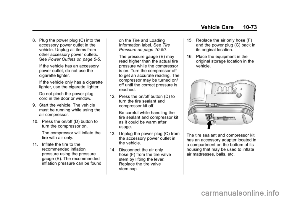
The tire sealant and compressor kit
has an accessory adapter located in
a compartment on the bottom of its
housing that may be used to inflate
air mattresses, balls, etc.
Page 327 of 394
Black plate (75,1)Chevrolet Cruze Owner Manual - 2011
Vehicle Care 10-75
Storing the Tire Sealant
and Compressor Kit
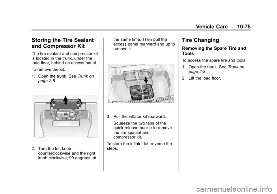
The tire sealant and compressor kit
is located in the trunk, under the
load floor, behind an access panel.
To remove the kit:
1. Open the trunk. SeeTrunk on
page 2‑8.
2. Turn the left knob counterclockwise and the right
knob clockwise, 90 degrees, at the same time. Then pull the
access panel rearward and up to
remove it.
3. Pull the inflator kit rearward.
Squeeze the two tabs of the
quick release buckle to remove
the tire sealant and
compressor kit.
To store the inflator kit, reverse the
steps.
Tire Changing
Removing the Spare Tire and
Tools
To access the spare tire and tools:
1. Open the trunk. See Trunk on
page 2‑8.
2. Lift the load floor.
Page 329 of 394
Black plate (77,1)Chevrolet Cruze Owner Manual - 2011
Vehicle Care 10-77
Removing the Flat Tire and
Installing the Spare Tire
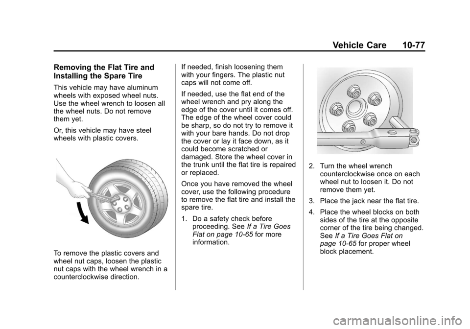
This vehicle may have aluminum
wheels with exposed wheel nuts.
Use the wheel wrench to loosen all
the wheel nuts. Do not remove
them yet.
Or, this vehicle may have steel
wheels with plastic covers.
To remove the plastic covers and
wheel nut caps, loosen the plastic
nut caps with the wheel wrench in a
counterclockwise direction.If needed, finish loosening them
with your fingers. The plastic nut
caps will not come off.
If needed, use the flat end of the
wheel wrench and pry along the
edge of the cover until it comes off.
The edge of the wheel cover could
be sharp, so do not try to remove it
with your bare hands. Do not drop
the cover or lay it face down, as it
could become scratched or
damaged. Store the wheel cover in
the trunk until the flat tire is repaired
or replaced.
Once you have removed the wheel
cover, use the following procedure
to remove the flat tire and install the
spare tire.
1. Do a safety check before
proceeding. See If a Tire Goes
Flat on page 10‑65 for more
information.
2. Turn the wheel wrench counterclockwise once on each
wheel nut to loosen it. Do not
remove them yet.
3. Place the jack near the flat tire.
4. Place the wheel blocks on both sides of the tire at the opposite
corner of the tire being changed.
See If a Tire Goes Flat on
page 10‑65 for proper wheel
block placement.
Page 386 of 394

Black plate (4,1)Chevrolet Cruze Owner Manual - 2011
i-4 INDEX
E
Electrical Equipment,Add-On . . . . . . . . . . . . . . . . . . . . . . 9-52
Electrical System Engine CompartmentFuse Block . . . . . . . . . . . . . . . . 10-37
Fuses and Circuit
Breakers . . . . . . . . . . . . . . . . . . 10-37
Instrument Panel Fuse Block . . . . . . . . . . . . . . . . . . . . . . 10-41
Overload . . . . . . . . . . . . . . . . . . . 10-36
Engine Air Cleaner/Filter . . . . . . . . . . . 10-15
Check and Service EngineSoon Light . . . . . . . . . . . . . . . . . . 5-13
Compartment Overview . . . . . . . 10-6
Coolant . . . . . . . . . . . . . . . . . . . . . 10-17
Coolant Temperature
Gauge . . . . . . . . . . . . . . . . . . . . . . 5-10
Cooling System . . . . . . . . . . . . . 10-16
Cooling System Messages . . . 5-30
Drive Belt Routing . . . . . . . . . . . . 12-4
Exhaust . . . . . . . . . . . . . . . . . . . . . . 9-24
Overheated Protection Operating Mode . . . . . . . . . . . 10-22
Overheating . . . . . . . . . . . . . . . . 10-20 Engine (cont.)
Power Messages . . . . . . . . . . . . . 5-31
Pressure Light . . . . . . . . . . . . . . . . 5-21
Reduced Power Light . . . . . . . . . 5-22
Running While Parked . . . . . . . . 9-25
Starting . . . . . . . . . . . . . . . . . . . . . . . 9-19
Engine Heater . . . . . . . . . . . . . . . . . 9-21
Engine Oil Life System . . . . . . . . . . . . . . . . . 10-12
Messages . . . . . . . . . . . . . . . . . . . . 5-30
Entry Lighting . . . . . . . . . . . . . . . . . . . 6-6
Equipment, Towing . . . . . . . . . . . . 9-51
Event Data Recorders . . . . . . . . 13-15
Exit Lighting . . . . . . . . . . . . . . . . . . . . 6-6
Extender, Safety Belt . . . . . . . . . . 3-23
Exterior Lamp Controls . . . . . . . . . 6-1
F
Filter Engine Air Cleaner . . . . . . . . . 10-15
Flash-to-Pass . . . . . . . . . . . . . . . . . . . 6-2
Flashers, Hazard Warning . . . . . . 6-3
Flat Tire . . . . . . . . . . . . . . . . . . . . . . 10-65
Flat Tire, Changing . . . . . . . . . . . 10-75
Floor Mats . . . . . . . . . . . . . . . . . . . . 10-97 Fluid
Automatic Transmission . . . . 10-13
Brakes . . . . . . . . . . . . . . . . . . . . . . 10-24
Power Steering . . . . . . . . . . . . . 10-22
Washer . . . . . . . . . . . . . . . . . . . . . 10-22
Fog Lamps Front . . . . . . . . . . . . . . . . . . . . . . . . . . 6-4
Folding Mirrors . . . . . . . . . . . . . . . . 2-12
Front Fog Lamps Light . . . . . . . . . . . . . . . . . . . . . . . . . . 5-23
Front Seats
Adjustment . . . . . . . . . . . . . . . . . . . . 3-3
Heated . . . . . . . . . . . . . . . . . . . . . . . . 3-7
Fuel . . . . . . . . . . . . . . . . . . . . . . . . . . . 9-40 Additives . . . . . . . . . . . . . . . . . . . . . 9-42
Filling a Portable FuelContainer . . . . . . . . . . . . . . . . . . . 9-44
Filling the Tank . . . . . . . . . . . . . . . 9-43
Fuels in Foreign Countries . . . . 9-41
Gasoline Specifications . . . . . . . 9-41
Gauge . . . . . . . . . . . . . . . . . . . . . . . . . 5-9
Low Fuel Warning Light . . . . . . . 5-21
Recommended . . . . . . . . . . . . . . . 9-40
Requirements, California . . . . . 9-41
System Messages . . . . . . . . . . . . 5-31
Page 393 of 394

Black plate (11,1)Chevrolet Cruze Owner Manual - 2011
INDEX i-11
Sun Visors . . . . . . . . . . . . . . . . . . . . . 2-16
Sunroof . . . . . . . . . . . . . . . . . . . . . . . . 2-17
Symbols . . . . . . . . . . . . . . . . . . . . . . . . . . iv
SystemInfotainment . . . . . . . . . . . . . . . . . . . 7-1
T
Tachometer . . . . . . . . . . . . . . . . . . . . . 5-9
TaillampsBulb Replacement . . . . . . . . . . 10-32
Text Telephone (TTY) Users . . . 13-4
Theft-Deterrent Systems . . . . . . . 2-10 Immobilizer . . . . . . . . . . . . . . . . . . . 2-10
Time . . . . . . . . . . . . . . . . . . . . . . . . . . . . 5-5
Tires Buying New Tires . . . . . . . . . . . 10-59
Chains . . . . . . . . . . . . . . . . . . . . . . 10-65
Changing . . . . . . . . . . . . . . . . . . . 10-75
Compact Spare . . . . . . . . . . . . . 10-83
Designations . . . . . . . . . . . . . . . 10-47
Different Size . . . . . . . . . . . . . . . 10-61
If a Tire Goes Flat . . . . . . . . . . 10-65
Inflation Monitor System . . . . 10-53
Inspection . . . . . . . . . . . . . . . . . . 10-56
Low Profile . . . . . . . . . . . . . . . . . 10-44
Messages . . . . . . . . . . . . . . . . . . . . 5-33 Tires (cont.)
Pressure Light . . . . . . . . . . . . . . . . 5-20
Pressure Monitor System . . . 10-52
Rotation . . . . . . . . . . . . . . . . . . . . 10-57
Sealant and
Compressor Kit . . . . . . . . . . . 10-68
Sealant and Compressor Kit, Storing . . . . . . . . . . . . . . . . 10-75
Sidewall Labeling . . . . . . . . . . . 10-44
Terminology and
Definitions . . . . . . . . . . . . . . . . . 10-47
Uniform Tire Quality Grading . . . . . . . . . . . . . . . . . . . 10-62
Wheel Alignment and Tire
Balance . . . . . . . . . . . . . . . . . . . 10-63
Wheel Replacement . . . . . . . . 10-64
When It Is Time for New Tires . . . . . . . . . . . . . . . . . . . . . . 10-58
Winter . . . . . . . . . . . . . . . . . . . . . . 10-43
Towing Driving Characteristics . . . . . . . . 9-46
Equipment . . . . . . . . . . . . . . . . . . . . 9-51
General Information . . . . . . . . . . 9-45 Towing (cont.)
Recreational Vehicle . . . . . . . . 10-87
Trailer . . . . . . . . . . . . . . . . . . 9-50, 9-51
Vehicle . . . . . . . . . . . . . . . . . . . . . 10-87
Traction Control System (TCS) . . . . . . . . 9-33
Control System (TCS)/StabiliTrak®Light . . . . . . . . . . . . 5-19
Off Light . . . . . . . . . . . . . . . . . . . . . . 5-19
Trailer Towing . . . . . . . . . . . 9-50, 9-51
Transmission Automatic . . . . . . . . . . . . . . . . . . . . . 9-26
Fluid, Automatic . . . . . . . . . . . . 10-13
Fluid, Manual . . . . . . . . . . . . . . . 10-14
Messages . . . . . . . . . . . . . . . . . . . . 5-34
Transportation Program, Courtesy . . . . . . . . . . . . . . . . . . . . . 13-8
Trip Odometer . . . . . . . . . . . . . . . . . . 5-9
Trunk . . . . . . . . . . . . . . . . . . . . . . . . . . . 2-8
Turn and Lane-Change
Signals . . . . . . . . . . . . . . . . . . . . . . . . 6-4
Turn Signal Bulb Replacement . . . . . . . . . . 10-32